Hill Audio PMA 1020 User manual

RevA 06-2014
PMA1020
PRECISION 2-WAY WIRELESS ACTIVE PA SYSTEM

Welcome
Thank you for choosing Hill Audio for your sound system. To make sure that this product meets your
expectations and provides long-term, reliable performance, please read and follow this instruction
manual carefully.
Manual Language
UK This user manual is written in English. For other languages, visit www.hill-audio.com
FR Ce guide est écrit en anglais. Pour les autres langues, visitez: www.hill-audio.com
DE Diese Anleitung ist in Englisch verfasst. Für andere Sprachen: www.hill-audio.com
ES Este manual está escrito en inglés. Para otros idiomas, visite: www.hill-audio.com
PT Este manual está escrito em inglês. Para outros idiomas, visite: www.hill-audio.com
IT Questo manuale è scritto in inglese. Per altre lingue, visitare: www.hill-audio.com
Important safety instructions
•Read these instructions and all markings on the product. Keep these instructions.
•Heed all warnings and instructions, both in this manual and on the product.
•Clean only with a dry cloth. Unplug from AC supply before cleaning.
•Do not use this product near water and avoid any exposure to water.
•Before connecting this product to any AC supply, make sure you check whether the AC mains
voltage and frequency match the indication on the product and its packaging.
•Only connect this product to an AC supply with sufficient power handling, protective earth connec-
tion, ground-fault (earth-fault) protection and overload protection.
•Disconnect the product from the AC supply during thunderstorms. Also disconnect from the mains
supply if the product is not being used for long periods.
•Make sure any heat sink or other cooling surface, or any air convection slot , is exposed sufficiently
to free air circulation and is not blocked.
•Do not operate this product in environmental temperatures exceeding 35 degrees Celsius and/or
85% relative humidity.
•Position the product in a safe and stable place for operation, out of reach of unauthorized persons.
•Make sure any cable connections to and from the product are neither subject to potentially destruc-
tive mechanical impact nor present any risk of stumbling or other accident risk to people.
•Audio equipment may generate sound pressure levels sufficient to cause permanent hearing
damage to persons. Always start up at low volume settings and avoid prolonged exposure to sound
pressure levels exceeding 90 dB.
•Do not open this product for service purposes. There are no user-serviceable parts inside. War-
ranty will be void in any case of unauthorized service by the user or other unauthorized persons.
•Take any precaution required by local law, applicable regulations or good business practice to avoid
injury to people or material damage by use of this product.
Explanation of symbols used in this manual and on the product:
DANGER!
Safety hazard.
Risk of injury or death.
WARNING!
Fire hazard.
WARNING!
Hazardous voltage.
Risk of severe or fatal
electric shock.
ATTENTION!
Read manual
before installation
and operation.
PAGE 1
USER MANUAL - PMA1020 PRECISION 2-WAY WIRELESS ACTIVE PA SYSTEM

PAGE 2
Description
The Tempo PMA1020 portable PA system is a completely self-contained, battery-powered mobile
sound system. The 10’’ woofer and a separate compression driver offer pristine sound quality. The
internal wireless microphones offer a plurality of hosting and presentation possibilities, while the built-
in media player offers comprehensive playback from USB and SD media. The Tempo PMA1020 is a
superior choice for all presenters, promoters, fitness instructors and anyone else who needs ultimate
mobility without compromising on sound and built quality.
Health advice
This unit produces and absorbs electromagnetic radiation. The strength of radiation and the sensitiv-
ity for disturbing interference matches the CE and FCC requirements. A corresponding sign is printed
on the backside of the unit. Any change or modification may affect the behavior of the unit concerning
electromagnetic radiation and it may not then meet CE requirements. The manufacturer takes no
responsibility in this case.
Functional advice
This unit is immune to the presence of electromagnetic disturbances – both conducted and radiated
- up to a certain level. Under peak conditions, the unit is classified to show a “class C” performance
criteria and may encounter temporary degradation or loss of function which may need manual help to
recover. In such case, disconnect the AC power from the unit and reconnect it again to recover.
Environmental advice
This unit is built to conform to the ROHS standards and the WEEE directive 2002/96/EC of the Euro-
pean Parliament and of the Council of the European Union. Under these regulations, the product shall
not be discarded into regular garbage at the end of its life, but shall be returned to authorized recy-
cling stations.
Unpacking
Please check that the box contains the following items:
Main parts: 1 pc. PMA1020 main unit
1 pc. Mains cable
1 pc. Handheld microphone or beltpack transmitter
1 pc. FM antenna
1 pc. Operation manual
If any part is missing, please contact your dealer immediately.
After unpacking, and before plugging the AC cord into the wall outlet, check whether the
AC mains voltage and frequency are compatible with this product (see rear panel of the
product). If the specified voltage or your AC plug do not match the local conditions, do
NOT plug the AC cord into the wall outlet and contact your dealer immediately.
Setting Up & Transport
When choosing a location for the PMA1020 PA system, keep the following in mind:
•
During transport or setup, avoid touching the cones of the loudspeakers with any object or
with your hands, as this could cause irreparable damage. Do not remove the protection grille.
•
Avoid pointing microphones in the direction of the speaker, as this could result in annoying
feedback, which can damage the speaker drivers.
•
When placing the system in an upright (vertical) position, make sure that the surface is flat
to avoid the PA system from tumbling or unintentionally moving due to rolling of the casters.
•
Avoid resonating floor positions for a better sound.
To use the telescopic handle for transport, press the button at the center of the handle to release it
USER MANUAL - PMA1020 PRECISION 2-WAY WIRELESS ACTIVE PA SYSTEM

PAGE 3
USER MANUAL - PMA1020 PRECISION 2-WAY WIRELESS ACTIVE PA SYSTEM
and pull the handle out. The handle has two positions, choose the one that
suits you best. To push the handle back down, press the button again.
Stand Mounting
The PMA1020 PA system is equipped with a 1-3/8 inch (35mm) stand
mount, to allow mounting on tripod stands. Make sure that:
•
The speaker stand is certified for being capable of supporting the
weight of the system.
•
The speaker stand is placed on a flat, stable surface and the tripod
legs are fully extended.
•
The speaker stand legs and any cables are out of the way of any
persons who may accidently trip over the stand or cables and pull
the PA system over.
Before lifting the PMA1020 onto the stand, make sure you can handle the
weight safely without injury to yourself, others, or damage to the system.
Functional Description
The PMA1020 is a portable, two-way, active PA system featuring three channels and up to two wire-
less microphones, plus a built-in media player with clear text display, which allows you to play MP3 files
from a USB memory key or SD card (see specific notes on media compatibility and file structure in
the “Files, folders and data conventions” section). The PMA1020 also features a two-band EQ, a
reverb processor and a three-jingle spot announcer, as well as a telescopic handle and casters for
easy transport, which make it an all-around yet simple solution for mobile performers of all kinds.
Top view
Front view Rear view
Wireless
transmitters
Beltpack
Handheld

7
6
PAGE 4
Controls and Connections
USER MANUAL - PMA1020 PRECISION 2-WAY WIRELESS ACTIVE PA SYSTEM
2
1
1
4
53
6 7
230V
2
3
4
5
AC inlet. Use the supplied AC cord to connect the unit to AC mains. Make sure voltage and
frequency stated and set on the unit comply with your local AC supply.
AC Voltage Selector Switch. Switches the AC supply voltage between 110/115V and
220/230V AC. The product ought to be preset to the voltage of your location, but it is recom-
mended to check this before first operation. Available settings are 230V and 115V
.
FUSE holder. The fuse can be removed and exchanged by turning the holder and pulling out the
holder tray. Switch the unit off and disconnect the AC supply before doing so. Replace fuses
only with same value and rating. If the fuse blows a second time, submit product for repair.
POWER switch. Turns the product on and off.
Make sure you switch the unit off when not in
use.
Battery CHARGING indicator. This LED illuminates red when the internal battery is being
charged. It takes approximately eight hours to fully charge the battery. Before using the
PMA1020 with the battery for the first time, charge the battery eight hours.
These four LEDs indicate the status of the internal battery. 100% indicates that the battery is
fully charged, providing up to 10 hours of battery life, depending on the usage. LOW indicates
that the battery life is not enough for the system to keep on working properly, in which case the
battery ought to be charged.
LINK output connector. This is a ¼" TRS jack to supply a line-level balanced audio signal to
external speakers, like the Andante series.

PAGE 5
POWER indicator. This LED indicates whether the product is switched on or off.
The MAIN LEVEL knob determines the overall volume of the system. Always verify that it is in
the OFF position before switching on or off the unit to avoid any unexpected thumps.
CH 1 source selector. This switch determines whether the signal of Channel 1 is taken from
the Line inputs
[11]
or
[12]
or the media player.
CH 1 AUX input. This stereo
minijack
input is meant for line-level audio outputs but it can also
be driven by headphone outputs.
CH 1 CD | TAPE audio input. This RCA inputs are meant for consumer level audio signals.
Note
that this input is disabled when a plug is inserted into the CH 1 AUX input [11].
CH 1 LEVEL control. Turning this control completely counterclockwise will reduce the respec-
tive signal to its minimum, while turning it clockwise increases the volume of the respective
signal.
To avoid any unexpected thumps and other noises, always verify that it is in the OFF posi-
tion before connecting any device into audio inputs
[11]
or
[12]
and before switching on or off
the unit.
CH 2 & CH 3 LINE/MIC sensitivity switches. Depending on the signal level supplied to the audio
inputs of channel 2 and 3 [15], the sensitivity can be selected between Line (released position)
and Microphone (pressed position) level. If the output of the feeding source is unknown, set the
sensitivity to Line first and try whether the audio level is sufficient.
CH 2 & CH 3 Audio input. These are electronically balanced inputs that accept either ¼" TRS
or male XLR plugs. If you connect a microphone into this input, it must be a dynamic-type
microphone that does not require phantom power.
USER MANUAL - PMA1020 PRECISION 2-WAY WIRELESS ACTIVE PA SYSTEM
8
9
10
11
12
13
14
15
15
8
12
11
14
16
10
13
18
17
9

PAGE 6
CH 2 & CH 3 LEVEL controls. Turning these controls completely counterclockwise will reduce
the respective signal to its minimum, while turning them clockwise increases the volume of the
respective signal.
To avoid any unexpected thumps and other noises, always verify that they
are in the OFF position before connecting any device into the respective audio inputs
[15]
and
before switching on or off the unit.
Master EQUALIZER. This two-band shelving EQ provides frequency response shaping of up to
±15dB to the mix of channels 1, 2 and 3. When set to the detented center position, the EQ
has no effect on the respective frequency band (LO or HI).
REVERB. This reverb processor affects only the wireless microphone signal of channel 1 and
the microphone signals of channels 2 and 3. Turning the REVERB control completely counter-
clockwise will disable the effect, while turning it clockwise increases the amount of effect
added to the microphone signal.
USER MANUAL - PMA1020 PRECISION 2-WAY WIRELESS ACTIVE PA SYSTEM
16
17
18
Display - Elements
21 31 32 33
34
35
38 39 40 41
36
37
19
22 23
25
26
24
20 30 21
29 28 27

PAGE 7
USER MANUAL - PMA1020 PRECISION 2-WAY WIRELESS ACTIVE PA SYSTEM
SD Card slot. Insert here a FAT32-formatted SD card of max. 16GB with a one-level folder
structure to play back MP3 files. If a USB memory stick is already inserted into
[20]
, the SD
card will be given priority.
USB port. Insert here a FAT32-formatted USB memory stick of max. 16GB with a one-level
folder structure to play back MP3 files. If a SD card is inserted into the respective slot
[19]
,
the SD card will be given priority. Note that this port does NOT support USB hard drives,
neither for memory size nor for power requirements.
Media player DISPLAY. Shows track/folder and time information, play status, playback mode
settings and play sequence settings. Details are described under items
[31...41]
.
DATA dial. Turn the control to choose a song or folder and press it to activate your selection.
FOLDER level button. Press to go UP to folder level, then navigate using the data dial
[22]
.
Playback MODE selector. There are four different modes available, the active one being
indicated on the display
[21]
:
• SPL = Single Play. The player stops after playing the current song once. The next song
is manually chosen by the dial
[22]
and determined by the chosen play sequence.
• SLO = Single Loop. The player loops the current song endlessly. The next song is
manually chosen by the dial
[22]
and is determined by the chosen play sequence.
• ACO = All Continuous. The player plays back all songs determined by the chosen
sequence and stops after the sequence is executed once.
• ALO = All Loop. The player plays back all songs determined by the chosen sequence
and repeats the sequence endlessly.
Playback SEQUENCE selector. Selects between
• Straight sequence: The next song is determined by alphanumerical sorting. The left
sequence mode indicator [• • •] is lit on the display
[39]
.
• Random sequence: The next song is determined by random choice. The right
sequence mode indicator [ ] is lit on the display
[39]
.
Media PLAY/PAUSE/STOP button. Press briefly to toggle between PLAY (backlight steadily lit)
and PAUSE (backlight flashing) mode. Press for longer than two seconds to switch to STOP
status (backlight off). Restart by pressing the button again, this will commence playback from
the last known position when in PAUSE mode or from the beginning of the chosen track when
in STOP mode. The selected status is displayed on the display
[41]
.
TIME Display selector. Selects between elapsed [E] and remaining [R] time display. The time
display choice is shown on the display
[32]
and is always related to the track currently playing.
IR Receiver sensor. If using the optional IR remote control (see page 12), make sure an unob-
structed line of sight is available between the remote control and the IR receiver sensor.
JINGLE buttons. Provided that the inserted media contains a folder named “Jingles” in its root
directory, and that the files in this folder follow certain naming conventions, up to three of
these files can be activated by the respective buttons (1, 2 or 3). When a jingle is activated,
the current program is muted and the jingle is played instead; however, the program
progresses in the background. A further scheduled jingle play mode is available by pressing
and holding the JINGLE 1 button for more than two seconds. The LED (30) will indicate that
the scheduled jingle play mode is active. To de-activate the scheduled jingle pay mode, press
again the JINGLE 1 button for more than two seconds. For more details, please see the “Jingle
player” section on page 9.
19
20
21
22
23
24
25
27
26
28
29

PAGE 8
Scheduled Jingle Play Mode Indicator. This LED is lit when the scheduled jingle play mode has
been activated by pressing the JINGLE 1 button (29) for more than two seconds.
Display Elements
Time Display. Depending on the setting of the Time Display selector (27), either the remaining
or elapsed time are displayed in HH:MM:SS format.
Time Mode Display (Elapsed): This icon indicates that the time displayed is the elapsed time of
the current track, according to the setting of
the Time Display selector
(27).
Time Mode Display (Remaining): This icon indicates that the time displayed is the remaining
time of the current track, according to the setting of
the Time Display selector
(27).
Numeric data display. This element of the display is not used in this product. This is NOT a
malfunction.
8-Digit Clear Text Readout.
The file name of the current track is shown, with its first 30 charac-
ters scrolling through the display. All characters beyond 30 characters will be discarded. Note
that this is NOT an ID3 tag readout, but a file name readout, so files must be named properly
to yield a sensible displayed content. The display will show the file name and alternate with the
folder name the current file is located in. Whether at a specific time the file or the folder name
is displayed, is indicated by the respective symbols, (36] and [37).
Folder Name Display Indicator. This icon indicates that the current content of the Clear text
readout (35) is a folder name.
File Name Display Indicator. This icon indicates that the current content of the Clear text read-
out (35) is a file name.
Source Mode Indicator. This element of the display is not used in this product. This is NOT a
malfunction.
Playback Sequence Indicator. This icon indicates whether the playback mode is set to straight
or random. The setting can be modified using the Playback SEQUENCE selector (25).
Playback Mode Indicator. Depending on the selection made with the
Playback MODE selector
(24), this element of the display shows the letters “SPL,” “SLO,” “ACO,” or ALO.“
Transport status indicators. Three standard symbols indicate whether the unit is in PLAY,
PAUSE or STOP status. The first (leftmost) indicator is not used in this product; this is NOT a
malfunction.
Notes on files, folders and data conventions
Due to the PMA1020 player’s hardware nature, it is subject to various restrictions, which are useful
to be aware of:
• Media Memory types. The PMA1020 player works only with SD cards and USB sticks of up
to 16GB formatted in FAT32 file system and containing maximum 2000 files. The player does
NOT support larger memory sizes, external hard disks or any media with NTFS formatting.
• Media File types. The PMA1020 can only read MP3 files in MPEG 1 Layer 3, MPEG 2 Layer
3, MPEG 2.5 Layer 3 standard, with sample rates of 128/160/192/224/256/320 kbps
+ VBR from solid-state memory media. Any other files existing on the solid-state memory
media will be ignored and are not available for playback.
USER MANUAL - PMA1020 PRECISION 2-WAY WIRELESS ACTIVE PA SYSTEM
31
32
33
34
35
36
37
38
39
40
41
30

PAGE 9
USER MANUAL - PMA1020 PRECISION 2-WAY WIRELESS ACTIVE PA SYSTEM
• File/Folder Structure. The PMA1020 only allows a two-layer folder structure on the solid
state media memory, meaning a root layer and a folder layer, but not cascaded folder-in-folder
structures. Such subfolders will be ignored and their content is not available for playback. Play-
able files located in the root layer are displayed in a folder named “ROOT” although this folder
does not physically exist on the solid-state memory media.
• Folder Sorting. Folders are displayed in the sequence of their creation date on the s olid-state
memory media. If a specific sequence is needed, then the folder shall be created in this
sequence on the memory media before copying any MP3 files into them.
• File Sorting. Files are sorted alphanumerically, but due to file system limitations, the sorting
is limited to the first eight characters. This may, in some cases — where the first eight charac-
ters are identical — lead to a seemingly random, non-alphabetical sequence.
• File system cache. In order to allow a relatively quick access to the file directory during naviga-
tion, the PMA1020 loads a copy of the file directory into its own memory upon insertion of the
solid-state memory media. This loading process requires some time, during which the display
shows a countdown. The time required is about four seconds per 100 tracks with a maximum
of 2000 tracks (meaning max. 80 seconds loading time).
• Displayed File/Folder names. The display scrolls the first 30 characters of the MP3 file
names; any characters beyond the first 30 will be ignored. Note that the display data is the file
name and NOT the ID3 tag of the file. Folders are displayed with the first 10 characters of their
names, any exceeding characters will be ignored.
Jingle Player
The PMA1020 features a jingle player with a one-shot mode for teasers and a scheduled mode for
commercial purposes (like playing advertisements in a certain sequence). To make use of the feature,
the user must create a folder named “Jingles” on the solid-state memory media. The folder must have
exactly this name (with capital J followed by lowercase letters) and will not be available for selection
during normal playback.
The jingle files stored in this folder have to be prepared with specific names as well, and have to follow
the structure jx_yy, where x is a number from 1 to 3 and yy a number from 00 to 99. In this format,
x defines the jingle number (with a maximum of three jingles allowed) and yy the number of minutes of
background music the jingle is followed by in scheduled jingle play mode. For example, were there to
be three jingles named j1_01.mp3, j2_04.mp3 and J3_05.mp3. These three jingles would be avail-
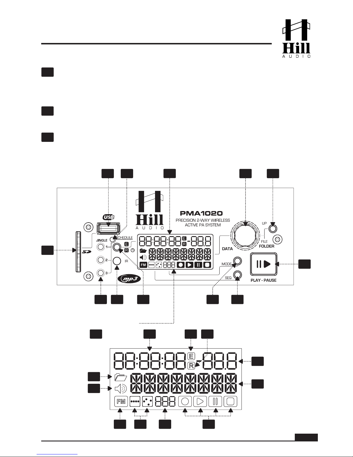
able for direct, one-shot playback pressing the jingle buttons (29), with each jingle assigned to the
respective button.
Scheduled jingle play mode can be activated by pressing and holding the J1 button for more than two
seconds. The jingles are, thus, inserted into the program in an automatic sequence with a certain
duration of background music in between. In the above example, Jingle 1 would start to play back
immediately followed by one minute of background music, then Jingle 2 followed by four minutes of
background music, then Jingle 3 followed by five minutes of background music. This sequence would
loop endlessly. If less jingles are stored in the Jingles folder, the loop runs after the last available jingle.
This means, for example, that if there is only one jingle named j1_02 stored in the Jingles folder, the
jingle would play every two minutes in Scheduled Jingle play mode.
Wireless Receiver
MIC ANTENNA connector. This BNC connector is meant for the wireless antenna supplied.
POWER-VOL control. Use this dial to turn on and off the receiver and to adjust the volume of
the wireless transmitter.
To switch on the receiver and increase the transmitter volume, turn
the control clockwise
. To switch off the receiver, turn the control fully counterclockwise until
you hear a click.
42
43

PAGE 10
USER MANUAL - PMA1020 PRECISION 2-WAY WIRELESS ACTIVE PA SYSTEM
Channel display. The number of the current channel is indicated here.
Channel UP & DOWN buttons. Press UP to increase the receiver’s channel and DOWN to
decrease it. There are 16 channels available. Once you select a channel for the receiver, you
must synchronize receiver and transmitter with the Auto-Sync Channel function [46].
ASC function. Once you have selected the channel for wireless transmission with the UP and
DOWN buttons [45], press the ASC button to automatically synchronize transmitter and
receiver. Align the infrared window of the handheld [53] or beltpack transmitter [62] with the
infrared window of the receiver [47].
Receiver IR window. This sensor sends infrared signals to the transmitter for channel synchro-
nization. For the synchronization to take place, the infrared window of the microphone [53] or
beltpack transmitter [62] must be aligned with the infrared window of the receiver.
RF indicator. This LED indicates whether the module receives a radio frequency signal (RF
signal) from the transmitter.
AF indicator. This LED indicates whether an audio signal is being received.
MUTE control. This control is used to adjust the squelch threshold for noise reduction when-
ever the transmitter is turned off or its signal is not strong enough. The mute level of the
receiver is preset from factory and, normally, no further adjustment is required. However,
should a readjustment be necessary, set the squelch threshold so that no noise is generated
in the receiver when the transmitter is off.
44
45
46
DOWN UP
44 48 46 47
42 49 43
45
ASC IR
RF
AF
MUTE LEVEL
POWER-VOL
UHF RECEIVER
DOWN UP
ASC IR
RF
AF
MUTE LEVEL
POWER-VOL
50
47
48
49
50

PAGE 11
USER MANUAL - PMA1020 PRECISION 2-WAY WIRELESS ACTIVE PA SYSTEM
Handheld Transmitter
The PMA1020 comes with a wireless handheld or beltpack transmitter (and an optional second one)
that syncs with the built-in RF receiver(s). To access the handheld microphone, open the storage com-
partment on the top of the PMA1020 by pushing down the compartment lid where indicated. To
close the compartment, simply press again until the compartment lid locks into place.
Always switch off the transmitter and keep it safely stored in the compartment when not in use.
GAIN control. This control determines the sensitivity of the microphone, which is preset from
factory to the optimum value for standard applications. If you need to modify this setting, turn
the control to the left to reduce the sensitivity or to the right to increase it.
RF switch. Use this switch to set the strength of the transmitter’s radio frequency signal. Set
to High for weak signals and Low for strong signals.
Transmitter IR window.
This sensor serves to synchronize transmitter and receiver. For chan-
nel synchronization, unscrew the body of the microphone and align the infrared window of the
transmitter with the infrared window of the receiver [47].
Battery compartment. The handheld transmitter uses two "AA" alkaline batteries (LR6, 1.5 V)
for an expected life of up to ten hours. To install or replace the batteries, unscrew the body of
the microphone and slide the batteries into position observing the polarity indicated.
When the
BATTERY/ASC indicator [55] flashes red, replace the batteries immediately.
BATTERY/ASC indicator. This LED indicates whether the microphone is on and has enough
battery (green LED permanently lit) or if the batteries are too low (the LED flashes red), in
which case you should replace them immediately. Further, the LED flashes green whenever
Auto-Sync Channel is taking place.
ON/OFF switch. Switches the transmitter on and off.
Make sure you switch the microphone off
when not in use to extend battery life.
Beltpack Transmitter
Antenna.
Power/Battery indicator. This LED illuminates green when the transmitter is on and has
enough battery to operate normally; otherwise, it lights up yellow when the battery is low. When
the LED flashes, it is indicative that infrared transmission is taking place.
Microphone INPUT. Use this mini-XLR plug to connect a dynamic microphone or a musical
instrument to the beltpack transmitter.
5556 54 53
51
52
51
52
53
54
55
56
57
58
59

PAGE 12
USER MANUAL - PMA1020 PRECISION 2-WAY WIRELESS ACTIVE PA SYSTEM
Input gain control.
Select the input sensitivity according to the connected source:
•
MIC for dynamic microphones,
•
0dB for guitars with passive pickups,
•
-10dB for guitars with active pickups.
Power switch. Three-way control to switch ON/OFF the beltpack transmitter and put it in
STANDBY mode (i.e. the output is muted).
Beltpack transmitter IR window.
This sensor serves to synchronize transmitter and receiver.
For channel synchronization, open the battery compartment [63] of the beltpack transmitter
and align the infrared window of the transmitter with the infrared window of the receiver [47].
Battery compartment.
The beltpack transmitter uses two "AA" alkaline batteries (LR6, 1.5 V)
for an expected life of up to ten hours. To install or replace the batteries, pull the compartment
lid down and slide the batteries into position observing the polarity indicated.
When the
power/battery indicator [58] lights up yellow, replace the batteries immediately.
Remote Control (optional)
The PMA1020 can be used together with an optional IR
(infrared) remote control. For proper opera
tion, a line of
sight between the remote control and the sensor on the
PMA1020 (28) is required. The IR remote controls only the
basic functions of the PMA1020 and, as such, adds conve-
nience to the operation, but does not replace the front panel
control on the unit itself.
Transport Controls. The four transport control
buttons allow you to start and pause a track, skip to
the next track or go back to the beginning of the
current track.
60
61
62
63
64
64
65
66
68
67
57 58
59
60
61
OPEN CLOSE
62 63

PAGE 13
USER MANUAL - PMA1020 PRECISION 2-WAY WIRELESS ACTIVE PA SYSTEM
Source button. This element is not used in this product. This is NOT a malfunction.
Mute button. Mutes and unmutes the output of the PMA1020 player.
Volume control (up/down). Allows you to set the required audio volume.
FM preset station buttons. This element is not used in this product. This is NOT a malfunction.
Connections
The PMA1020 uses the connection types shown below. The pin convention must be followed. Always
make sure to use good connectors and cables to ensure proper operation. Balanced connections are
to be preferred over unbalanced connections where applicable and feasible. Avoid unbalanced
connections exceeding 2m of cable length.
65
66
67
68
CABLE Types
1-conductor shielded cable
(for unbalanced connections)
red
shield
2-conductor shielded cable
(for balanced connections)
red
shield
black
tip
sleeve
tip
sleeve
red = tip
shield = sleeve
red = tip
black = sleeve
shield = uncon.
3
1
2plug
side 3
1
2
cable
side
red = 2
black = 3
shield = 1
red = 2
shield = 1+3
2
3
1
3
1
2
3
1
2
cable
side
plug
side
red = 2
black = 3
shield = 1
red = 2
shield = 1+3
tip
sleeve
ring tip
sleeve
ring
red = tip
shield = sleeve+ring
red = tip
black = ring
shield = sleeve
tip
sleeve
tip
sleeve
ring ring
red = tip
shield = sleeve+ring
red = tip
black = ring
shield = sleeve
tip
sleeve
tip
sleeve
red = tip
shield = sleeve
red = tip
black = sleeve
shield = uncon.
XLR male
XLR female
6.35mm TRS-stereo
6.35mm TRS-mono
3.5mm TRS-stereo
RCA
CABLE Types
Structure Balanced
connection
Unbalanced
connection

USER MANUAL - PMA1020 PRECISION 2-WAY WIRELESS ACTIVE PA SYSTEM
Maintenance and warranty
While we have chosen the best components to make this product as rugged and reliable as possible, some parts in audio
products (potentiometers, faders, switches) are subject to wear, which is a matter of operation cycles, not of time. While
we provide a full time-based warranty on the electronic circuitry according to the legal requirements of the country of
purchase, we limit the warranty on such electromechanical parts to 90 days from the date of purchase.
In many cases, malfunction of electromechanical parts occurs due to dust contamination, which may require cleaning of
such parts. As the inside of such parts is not accessible, a common practice is to use cleaning fluids in the shape of sprays.
Please be reminded that many of such fluids contain chemicals which may wash away the dust but, at the same time,
corrode or damage contact surface and may cause cosmetic damage to other parts. We hence explicitly exclude any
claims for exchange of damaged parts due to mechanical or chemical impact.
Technical Specifications
Channel 1: RCA & 3.5mm line inputs
Channels 2 & 3: 6.35mm TRS/XLR combo line/mic inputs
6.35mm TRS link output
80 W into 4 ohms
40 W into 8 ohms
10" with 2" VC 40 oz. magnet
1" ferrite compression driver
60 Hz - 20 kHz
118 dB
USB/SD MP3 player (
MPEG 1 Layer 3, MPEG 2 Layer 3, and
MPEG 2.5 Layer 3 at 128, 160, 192, 224, 256, 320 kbps + VBR)
Shelving filters at 80 Hz (Low) and 12 kHz (High), ±15dB
35 mm stand pole
Die-cast telescopic top handle
360 x 560 x 303 mm
17.5 kg
16
863 - 865 MHz
60 Hz - 16 kHz
> 100 dB
<1%
FM
Dynamic (handheld)
Cardioid (handheld)
10 mW (handheld and beltpack)
6 mV (beltpack)
> 102 dB (handheld and beltpack)
235 x 54 mm (handheld), 85 x 65 x 24 mm (beltpack)
280 g (handheld), 80 g (beltpack)
2 x "AA" batteries (handheld and beltpack)
Approximately 10 hours (handheld and beltpack)
Inputs
Outputs
LF amplifier
HF amplifier
LF driver
HF driver
Freq. response
Maximum SPL
Player
EQ
Pole socket
Handle
Dimensions (WxHxD)
Net weight
Channels
Carrier frequency range
Audio bandwidth
SNR (receiver)
THD (receiver)
Modulation
Capsule type
Polar pattern
Output power
Maximum input level
SNR (transmitter)
Dimensions
Net weight
Power req. (transmitter)
Battery life (transmitter)
Main system
specifications
Receiver
and
transmitters

www.hill-audio.com
Hill Audio products are developed, manufactured and distributed by
Adelto Technologies
Vanguard Way, Shoeburyness, Essex SS3 9QY, UK
EC Declaration of Conformity
Manufacturer: Adelto Technologies Limited
Address: Vanguard Way, Shoeburyness, Essex SS3 9QY, UK
We declare on our own responsibility, that the equipment
Hill Audio PMA1020
is in conformity with the following directives and standards or regulations:
EMC Directive 2004/108/EC
EN55022:2010 (Emissions)
EN55024:2010 (Immunity)
EN61000-3-3:2008
EN61000-4-2 /-3 /-4 /-5 /-11
LVD Directive 2006/95/EC
EN60065:2002 A1:2009 + A11:2008 + A2:2010 + A12:2011
ROHS Directive 2002/95/EC
and is marked as follows:
Shoeburyness, 2. May 2014
Authorized SignaturePlace and date of issuing
R+TTE Directive 1999/5/EC
EN301489-1:2011
EN301489-9:2007
EN301489-17:2012
EN300422-1: 2011
EN300422-2: 2011
EN62479:2010
Table of contents
Other Hill Audio Speakers manuals