Hiniker 2754 User manual

PICKUP TRUCK SNOWPLOW
STEEL STRAIGHT PLOW
Models 2754, 2804, 2854
ASSEMBLY INSTRUCTIONS
DO NOT USE OR OPERATE THIS EQUIPMENT UNTIL THIS MANUAL
HAS BEEN READ AND THOROUGHLY UNDERSTOOD
PART NUMBER 25014882
Please visit www.snowplows.hiniker.com to access the most recent version


TABLE OF CONTENTS
GENERAL PLOW ASSEMBLY...................................................................................................... 2
FRAME TO MOLDBOARD ASSEMBLY........................................................................................ 3
HYDRAULICS ASSEMBLY ........................................................................................................... 4
PLOW ELECTRONICS ASSEMBLY ............................................................................................. 5
TRUCK ELECTRONICS & MOUNT KIT ASSEMBLY.................................................................... 7
SYSTEM CHECKOUT................................................................................................................. 10
CONTROLLER CONFIGURATION ............................................................................................. 12
HEADLAMP AIMING PROCEDURE ........................................................................................... 13
WARRANTY ................................................................................................................................ 14
Table of Contents 1
25014882 8/2023 Hiniker/25014882

GENERAL PLOW ASSEMBLY
WARNING: To prevent personal injury or
death, be certain to keep clear of any parts
that may drop when removing bun-
dling straps, wires or brackets. Sup-
port heavy sections with hoist or
blocks before removing wires or straps.
In the following instructions, left and right ma-
chine references are defined as being viewed
from the cab of the truck.
Be certain that hydraulic hoses and electrical
wires are safely routed and allow full motion of
moving parts. Secure loose wires with plastic tie
straps.
Some components are fastened at incorrect lo-
cations for shipping purposes.
All hardware should be tightened only enough
to ensure safety during assembly. Torque hard-
ware to specied values, as shown in the fol-
lowing chart, only after assembly has been com-
pleted.
GRADE 5 TYPE B & F LOCK NUT
TORQUE VALUES
Size Ft-lbs. N-m
5/16” 13-18 17-25
3/8” 23-33 31-44
1/2” 58-82 79-112
5/8” 117-165 158-223
GRADE 5 BOLT TORQUE VALUES*
Size Ft-lbs. N-m
1/4” 8-12 11-16
3/8” 29-41 39-56
1/2” 73-103 99-140
5/8” 146-206 198-279
* applications without lock nuts
Replace worn bolts and lock nuts with
grade 5 bolts and equivalent type B and type F
lock nuts. Type B lock nuts are plain hex; type F
lock nuts are flanged hex.
WARNING: Snow plow has O-ring hydraulic
fittings on the pump, hoses and hydraulic
cylinders. DO NOT use pipe sealant or
over tighten during assembly.
After assembly validate all hydraulic connec-
tions are tight. Factory installed connections
may loosen during shipping.
NOTE: New hydraulic cylinders will leak a small
amount of oil until packings become saturated
and produce a good seal. If leakage is exessive,
or if leaking continues after initial cycling, tighten
the packing nut in 1/8 turn increments until leak-
ing stops.
NOTE: Discard any lock nuts removed while
transitioning the plow from shipping congura-
tion to nal conguration. Utilize new lock nuts
provided in Op manual bag.
2 General Plow Assembly
Frame to Moldboard Assembly 3
FRAME TO MOLDBOARD ASSEMBLY
1. Place moldboard face down on cardboard
or other padding that will prevent scratches
in the paint.
Remove two side markers and four ship-
ping straps from the ends of the moldboard.
NOTE: Additional compression springs are in-
cluded with 8 1/2’ moldboards. Remove springs
and set aside for reassembly.
2. Open the frame box and set aside the hard-
ware bag, power unit box and electronics box
for later assembly. Remove the frame as-
sembly from the shipping box to a piece of
cardboard or other padding that will prevent
scratches in the paint.
NOTE: If assembling an 8 1/2’ plow, remove
endcaps from compression springs and install
an extra spring inside each existing spring.
Place endcaps on springs and tighten 3/4” lock
nuts on pullrods until the outer springs measure
13” long. Do not overtighten springs.
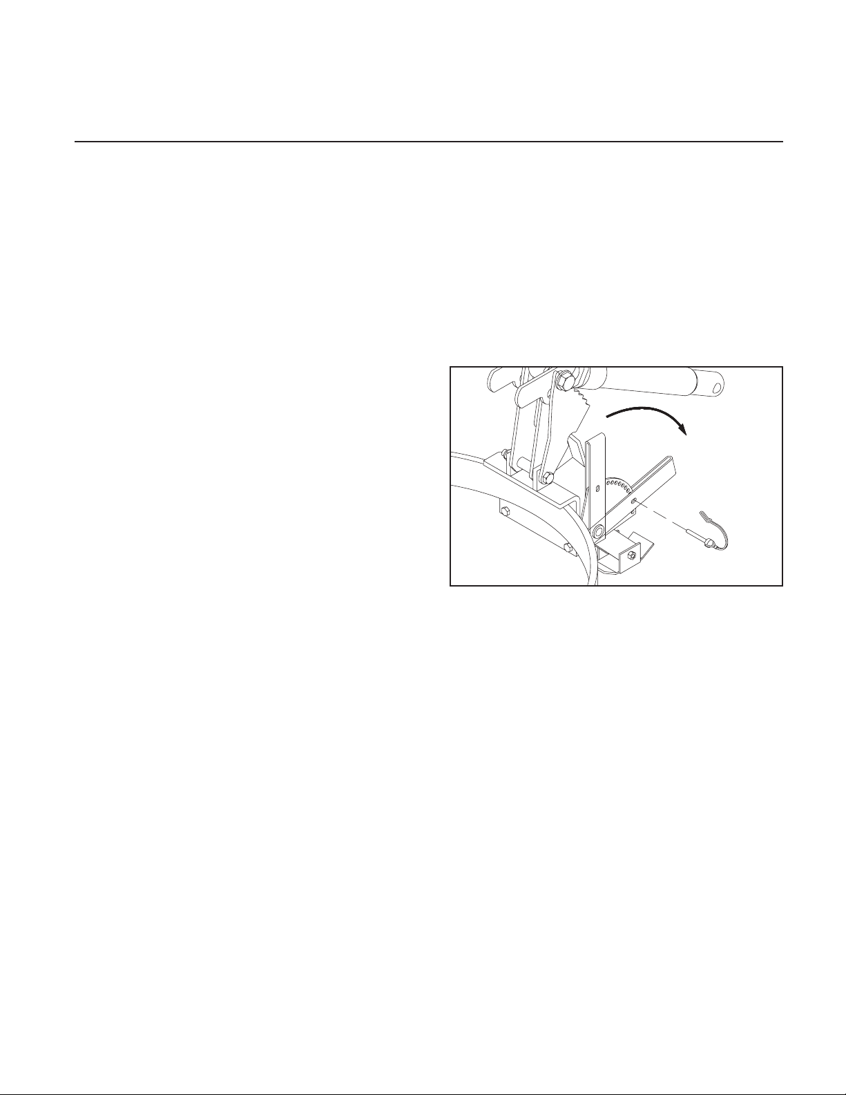
3. Gently tip the plow assembly to its working
position with a hoist or forklift. Pin the
parking stand to hold the square tubes of
the push frame parallel to the ground.
DWG NO. 4201A
NOTE: The bottom surface inside the two prong
receiver channels should measure about 10”
above the ground in the working position.
Carefully lift the frame assembly by wrap-
ping straps or padded chains around both
ends of the 2 1/2” square tube at the rear of
the frame. Attach the frame assembly to the
moldboard by lining up the three bushings
on the frame with the three sets of bushings
on the moldboard.
Apply commercially available anti-seize lu-
bricant (not supplied) to the hinge pins to
prevent future corrosion, and reinstall the
hinge pins through the bushings. Secure
the hinge pins with spring pins.
Remove 3/4” lock nuts from the back of
each compression spring and discard. Align
each pullrod bushing with the upper set of
holes in the moldboard ribs and reinstall
5/8” bolts and lock nuts. Tighten lock nuts
only until snug against ribs.
Assemble new 3/4” lock nuts back onto
pullrods and tighten until compression
springs measure 13” long. Do not overtight-
en springs.
HYDRAULIC ASSEMBLY
1. For Halogen lights Only: Before assembling
the power unit on the lift frame, scrape a
small amount of paint from the two mount
holes in the lift frame to provide a good
electrical ground for the turn signals and
parking lights.
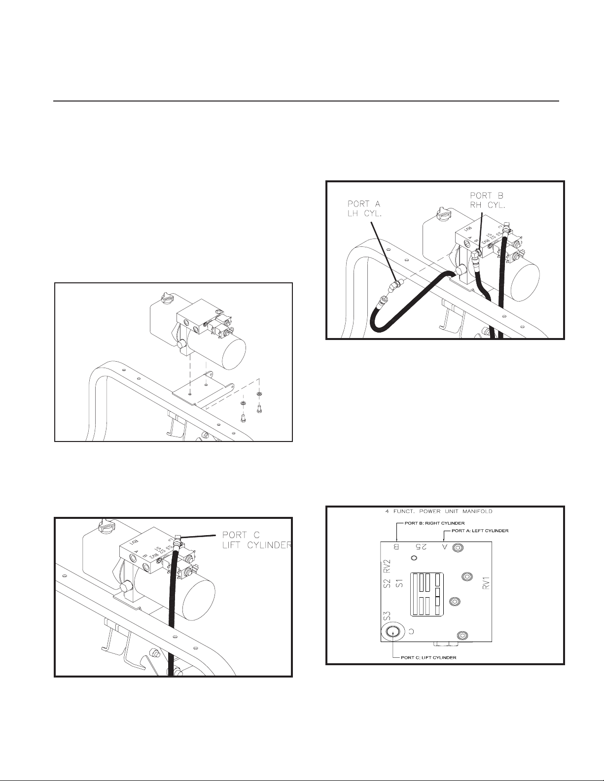
2. Mount the power unit on the lift frame with
two 3/8” x 3/4” hex bolts and two 3/8” lock
washers. The plastic reservoir of the power
unit should be to the left side of the plow,
see following illustration.
DWG NO. 6595A
DWG. NO. 6484A
3. Install the adapters into power unit, then
fasten the hoses to the adapters matching
the letter ends to the letters on the mani-
fold.
DWG NO. 6485A
4. Ensure factory installed ttings are tight.
Then secure hoses ensuring they clear the
lift links and latch handle.
NOTE: The tting in the LH side angling cylin-
der may have to be adjusted slightly to route the
hydraulic hose to best avoid interference with
the latch handle and the lift links. Use plastic tie
straps to secure all hydraulic hoses away from lift
link stops.
DWG NO. 4fct Manifold
4 Hydraulic Assembly
Plow Electronics Assembly 5
PLOW ELECTRONICS ASSEMBLY
NOTE: Check 1/4” bolts provided in LED head-
light box. If they do not have a pre applied Loc-
tite patch, apply anti-sieze to the bolts to pre-
vent galling.
NOTE: Do not use an impact driver, tighten
bolts by hand to prevent galling and damage to
headlight housing.
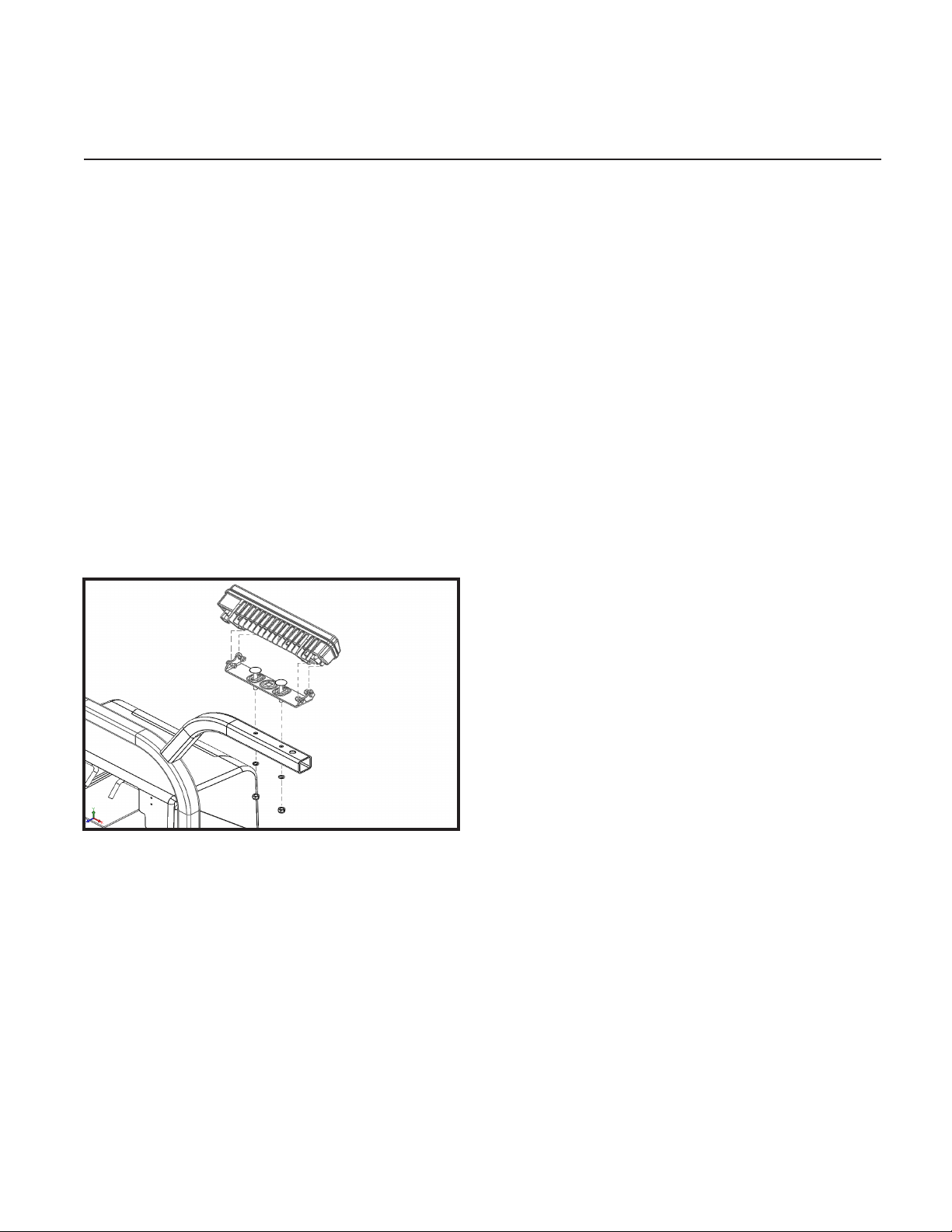
1. Mount the headlamp brackets to the lift
frame tube with hardware provided in light
parts box.
Remove the LH and RH headlamps from their
box and mount on the brackets with the pro-
vided hardware.
Refer to section titled “Headlamp Aiming
Procedure” for aiming instructions.
DWG. NO. 6012F
2. Take the 38” power cable (38812008) from
the electronics parts box and the plow side
harness (38813155 for LED) or (38813098
for Halogen) from the headlight parts box.
NOTE: To prevent corrosion lightly coat all elec-
trical connections, ring and spade terminals with
dielectric grease prior to assembly.
3. Fasten the ring terminal of the solid black wire
of the power cable assembly to the stud that
the solenoid ground cables are running to on
the motor.
4. Attach the ring terminal of the red striped wire
of the power cable assembly to the unoccu-
pied terminal on the motor.
5. Connect the RH headlamp to the har-
ness end labeled “PSNGR SIDE” and the
LH headlamp to the end labeled “DRIVER
SIDE”.
6 Plow Electronics Assembly
Wire to Solenoid Chart
4 Function V-Plow C-Plow
Tan S2 S1 S1
Pink not used S2 S4
Gray S1 S3 S2
Blue w/ White not used S5 S5
Blue S3 S6 S6
Brown not used S4 S3
NOTE: Install the plow harness so that water
does not run down the wires and pool inside the
“Y” connection. Position the harness so that any
trapped water can easily drain away.
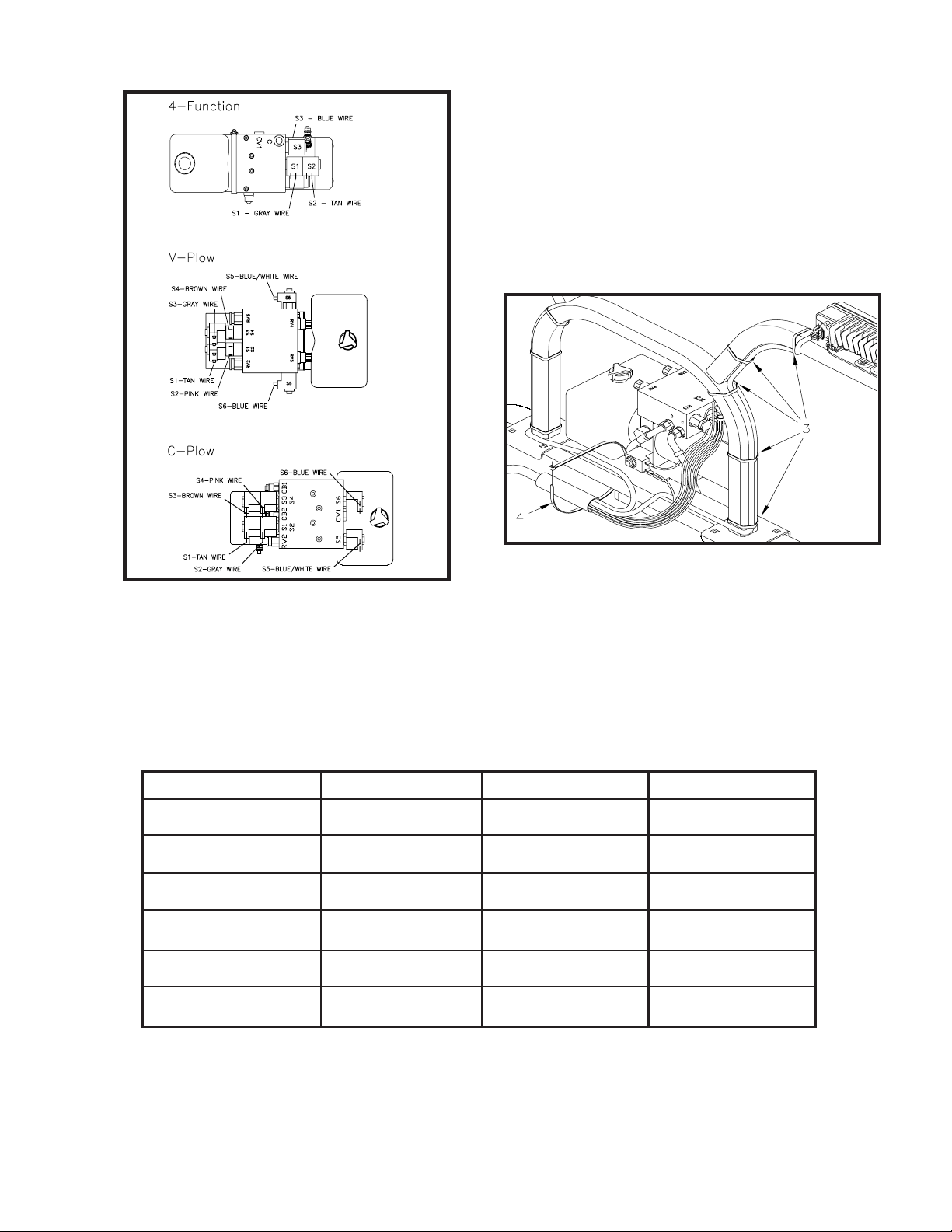
7. Refer to drawing 6013F. Use plastic tie
straps to secure plow wiring harness to lift
frame tube and headlamp bracket at the lo-
cations shown by arrows 3 and 4.
DWG. NO. 6013F
DWG. NO. 8007
6. Refer to drawing 8007 and the chart below
to connect the plow wiring harness to the
power unit solenoids.

TRUCK ELECTRONICS & MOUNT KIT ASSEMBLY
Truck Battery On Passenger Side
WARNING: Disconnect truck battery before
beginning electrical installation to avoid
shock hazard.
Open the electronics parts box and validate you
have all components, harnesses, and hardware
per the checklist inside the box.
NOTE: To prevent corrosion, apply a light coat
of dielectric grease on all connectors and termi-
nals before installation.
1. Refer to drawing 8000 & 8001 for a general
guide on routing the HTBX electrical system
harnesses. Not all engine compartments
are compatible with the routing shown in
the drawings 8000 & 8001. Installers must
use their best judgement to route the har-
nesses ensuring everything is secured from
hot or moving components.
2. If there is no access hole in the driver’s
side rewall then drill a 1” diameter hole.
Route the 12 pin rectangular connector of
the controller harness (38828011) from the
HTBX controller through the rewall into the
cab compartment. If required, install the 4”
grommet in the hole.
CAUTION: Ensure that the electrical system
will clear any hood lift/spring mecha-
nisms before installation.
Truck Electronics & Mount Kit Assembly 7
Wire to Solenoid Chart
4 Function V-Plow C-Plow
Tan S2 S1 S1
Pink not used S2 S4
Gray S1 S3 S2
Blue w/ White not used S5 S5
Blue S3 S6 S6
Brown not used S4 S3
NOTE: Install the plow harness so that water
does not run down the wires and pool inside the
“Y” connection. Position the harness so that any
trapped water can easily drain away.
7. Refer to drawing 6013F. Use plastic tie
straps to secure plow wiring harness to lift
frame tube and headlamp bracket at the lo-
cations shown by arrows 3 and 4.
DWG. NO. 6013F
DWG. NO. 8007
6. Refer to drawing 8007 and the chart below
to connect the plow wiring harness to the
power unit solenoids.

8 Truck Electronics & Mount Kit Assembly
Truck Battery On Driver Side
3. Splice the yellow wire to the vehicle’s 12
volt auxiliary electrical circuit. This will pre-
vent operation of the plow without the ve-
hicle’s key being on.
4. Connect the dark blue end of the cab har-
ness (38828030) to the controller harness
(38828012) inside the truck cab. Then con-
nect the black & white end of the cab har-
ness to the universal controller (38828019),
Refer to the controller conguration section
for instruction on how to congure the con-
troller with the correct plow setting, and the
operators preferred joystick conguration.
Once congured, secure the case together
with the provided hardware.
CAUTION: To prevent injury or property dam-
age caused by unintentional plow
movement when the key is removed
from the vehicle, the yellow wire must
be connected to a switched power source on
the vehicle. Connecting to a power source
not controlled by the ignition switch will allow
movement of the plow with the vehicle key re-
moved.
DWG. NO. 8006

CAUTION: Ensure that the electrical system
will clear any hood lift/spring mecha-
nisms before installation.
NOTE: Do not over tighten nuts on the motor
solenoid terminals. Over-tightening causes pre-
mature solenoid failure. Refer to torque specica-
tions on the solenoid.
5. Select an area within 16” of the vehicle
battery for the motor solenoid placement.
Using the solenoid bracket as a template,
mark and drill two 3/16” diameter holes then
fasten the solenoid with two 1/4” x 1/2” long
self tapping screws provided in the electri-
cal parts box.
6. Safely route the 16 pin plow harness
(38828012) from the HTBX controller
through the grill of the vehicle to a location
that will be easily accessible with the plow
attached.
7. Refer to drawings 8000 or 8001 for con-
necting the power cable and harness:
a. Connect the black terminal from the 9’
battery cable (38813066) and the black
wire from the power harness (38828016) to
the minus(-) post of the vehicle’s battery or
the vehicle’s designated ground stud.
b. Connect the red striped terminal from the
9’ battery cable (38813066) to the motor so-
lenoid then route the battery cable through
the grill near the 16 pin plow connector.
c. Connect the 24” red cable to the motor
solenoid.
d. Connect the red fused wire from the pow-
er harness (3882016) and the free end of
the 24” red cable to the plus(+) terminal of
the battery or battery access post.
e. Connect the black wire & the blue wire
from the power harness (38828016) to the
small posts of the motor solenoid, polarity is
not important.
8. See instruction sheet provided with vehicle
specific harness for hooking up the HTBX
system to the vehicle’s headlights.
9. To complete the electrical installtion: con-
nect all harnesses to the HTBX controller
and secure all harnesses & cables away
from hot or moving components with the
provided cable ties.
10. See instruction sheet provided with the ve-
hicle specific mount kit to finalize the ve-
hicle part of the plow installation.
NOTE: Prongs from the mount kit should be at a
height that will slightly lift the plow frame when
attaching the plow. General rule of thumb is 9”
from the ground to the underside of the prong.
This can vary if the truck has a modified sus-
pension.
NOTE: Powdered graphite can be used on the
prongs to help the plow slide on and off more
easily.
NOTE: Prong receivers on the plow frame must
be parallel to the ground before attaching the
plow. Always follow the attaching and detaching
instructions that are decaled on the rear side of
the plow blade.
Truck Electronics & Mount Kit Assembly 9
10 System Checkout
SYSTEM CHECKOUT
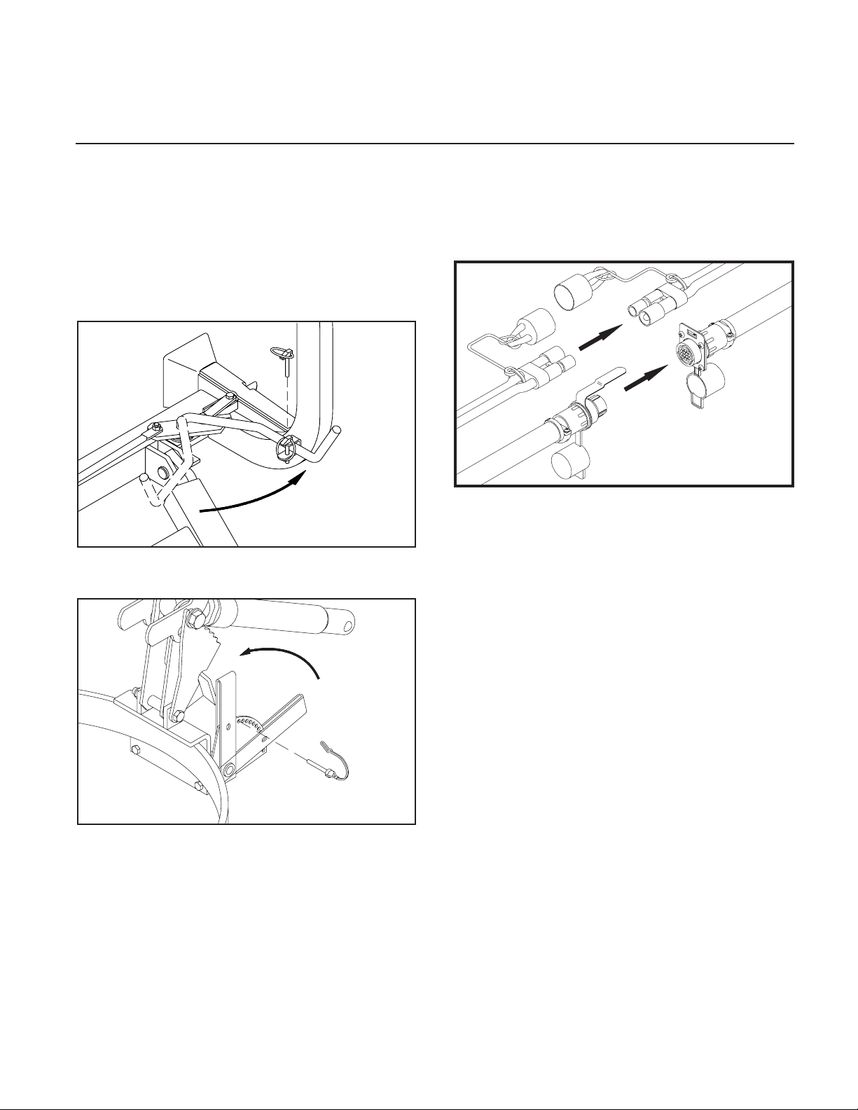
1. Prongs from the truck mount kit should
be at a height that will slightly lift the plow
frame when attaching the plow. Prong re-
ceivers on the plow frame should be paral-
lel to the ground when attaching the plow.
Apply powered graphite on the truck prongs
to help the plow to slide on and o more
easily.
Handle Pinned With Plow on Truck DWG NO. 4199
DWG NO. 5286A
2. Connect the electrical cables from the plow
to their corresponding receptacles on the
truck. Validate the power connection is red
stripe to red stripe and black to black.
DWG. NO. 6697
3. Select Hiniker Cold Flow Hydraulic Oil or
an equivalent oil that meets military speci-
fication 5606, for plowing in extremely cold
temperatures.
Pour hydraulic oil into the power unit oil
reservoir until the reservoir is half full.
Angle the plow full left or right with the cab
control box inside the truck to fill the an-
gling cylinder with oil. Add more oil until the
reservoir is about 3/4 full. Do not over-fill
the reservoir.
Cycle the plow left and right and up and
down to purge any air trapped in the hy-
draulic system.
Check the oil level with the plow on the
ground. Add oil to the fill line, if necessary,
but do not over fill the reservoir.
NOTE: New hydraulic cylinders will leak a small
amount of oil until packings become saturated
and produce a good seal. If leakage is exces-
sive, or if leaking continues after initial cycling,
tighten the cylinder packing nut in 1/8-turn in-
crements until leaking stops.

4. Fasten the power unit cover assembly to the
lift frame bracket with two 1/4” x 3/4” screws,
at washers and lock nuts from the hardware
bag in the power unit box. Tighten the lock
nuts so that the assembly is secure, yet the
cover hinges freely.
DWG. NO. 6310
NOTE: When the cover is closed, rods from the
latch handles should extend behind the light
brackets to hold the cover in place.
DWG. NO. 6014D
5. Assemble side markers on the ends of the
moldboard with 5/16” bolts, at washers
and lock nuts.
DWG. NO. 6006
NOTE: The power cable and wiring harness
must be connected between the snowplow and
truck to test the functions of the headlights and
power unit. Vehicle ignition must be switched
on.
6. Move the headlight switch on the joystick con-
troller to the “TRUCK” position and turn on
the vehicle headlights. High and low beams
should operate on the truck.
7. Turn the vehicles headlight switch to its o
position then move the switch to the “PLOW”
position. Plow lights should operate in both
high and low beams. Vehicle headlights
should be o.
8. Test the parking lights and turn signals. Lights
on the plow and truck should operate at the
same time.
9. In an area clear of bystanders, test joystick
functions by raising and lowering the plow
and angling side to side.
NOTE: To reverse the angle functions, exchange
the tan and gray wires on the power unit.
Refer to the section titled “Controller Congura-
tion” for instructions on inverting the raise and
lower functions.
System Checkout 11
CONTROLLER CONFIGURATION
NOTE: The 2 pin power cable and 16 pin plow har-
ness must be connected, and the vehicle’s ignition
switch must be switched on in order to test the
functions of the headlights and power unit.
1. Ensure the black and white 12 pin connec-
tor from the cab harness is attached to the
controller.
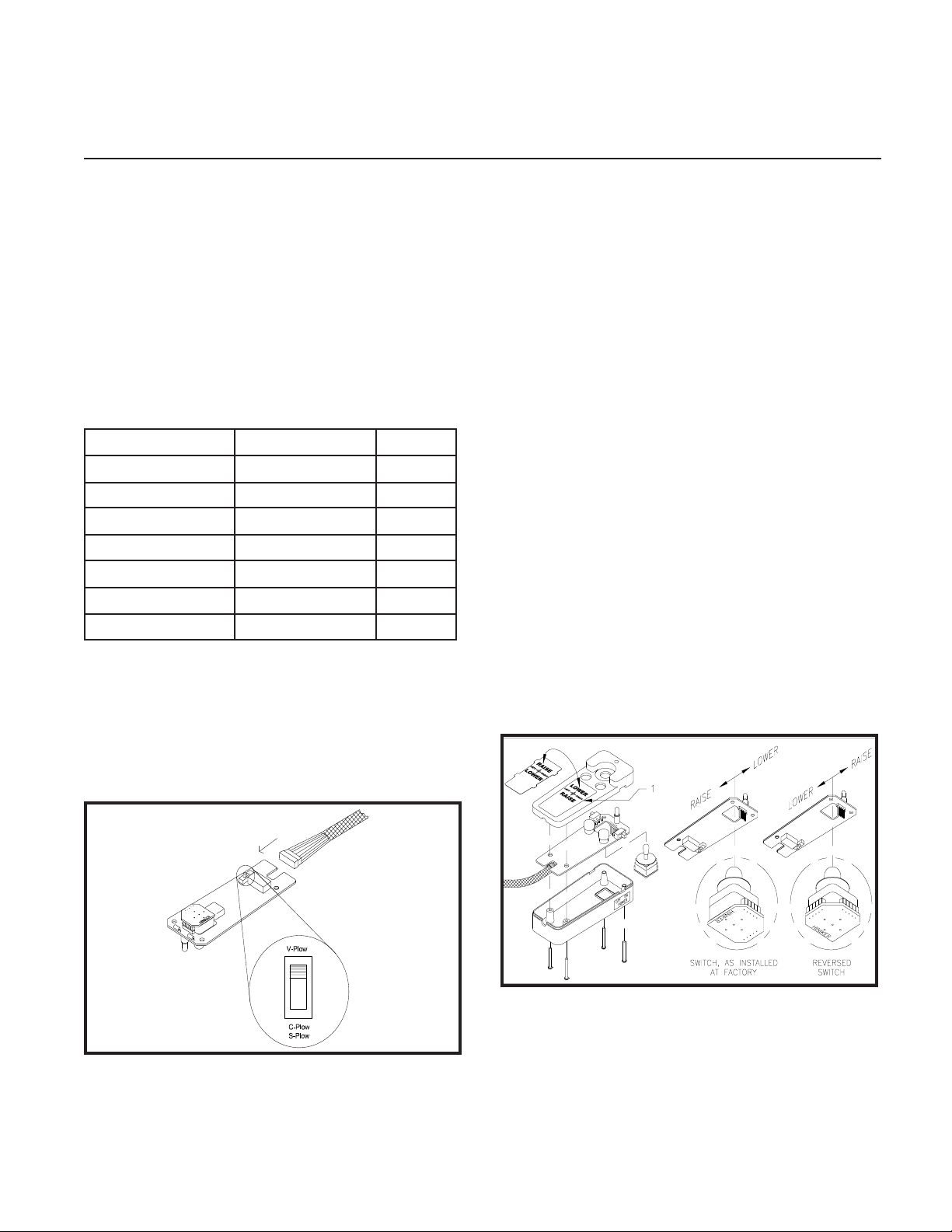
2. Use the plow selection switch to select
whether you have a V-Plow or a Straight
Blade.
Model Plow Type Postion
9585, 9595 Torsion V Up
9863, 9963, 9710 Compression V Up
2754, 2804, 2854 Steel Straight Down
8804, 8904 CDown
6814, 6914 Scoop Down
7814, 7914 Poly Straight Down
703, 753 Mid Size Straight Down
NOTE: As supplied from the factory, the snow-
plow controller raises the plow when the joystick
is pulled backward and lowers the plow when
the joystick is pushed forward. If you wish to re-
verse this follow steps 3 through 5. If not, skip
to step 6.
DWG. NO. 8006
3. Pry the face plate of the controller by insert-
ing a small screwdriver along the side of the
plate of the plate at location 1 in drawing
5855A. Flip the plate over, then reinstall by
gently sliding the 4 tabs into the slots in the
controller top.
4. To reverse the joystick switch, gently pull on
the edges of the small circuit board at the
base of the joystick switch to remove the
switch from the 5 pins on the main circuit
board.
5. Rotate the switch 90 degrees then gently
push the switch back onto the 5 pins.
6. Insert the main circuit board into the case
top ensuring the joystick is properly seated
and the harness strain relief is inside the
case.
7. Assemble the case with the provided
screws.
8. Test the controller on the snow plow to ver-
ify that raise and lower functions are what
the operator desires.
DWG. NO. 5855A
12 Controller Conguration
HEADLAMP AIMING PROCEDURE
NOTE: Headlamp aiming should be done while
plow is in a raised position.
NOTE: This procedure should be done with no
load on the vehicle other than the driver, snow-
plow, and rear ballast weight, inspect the vehicle
for proper tire in ation and broken or sagging sus-
pension components. Check functioning of any
automatic vehicle leveling systems and any spe-
ci c manufacturer’s instructions pertaining to ve-
hicle preparation for headlamp aiming. Stabilize
the suspension by rocking the vehicle sideways.
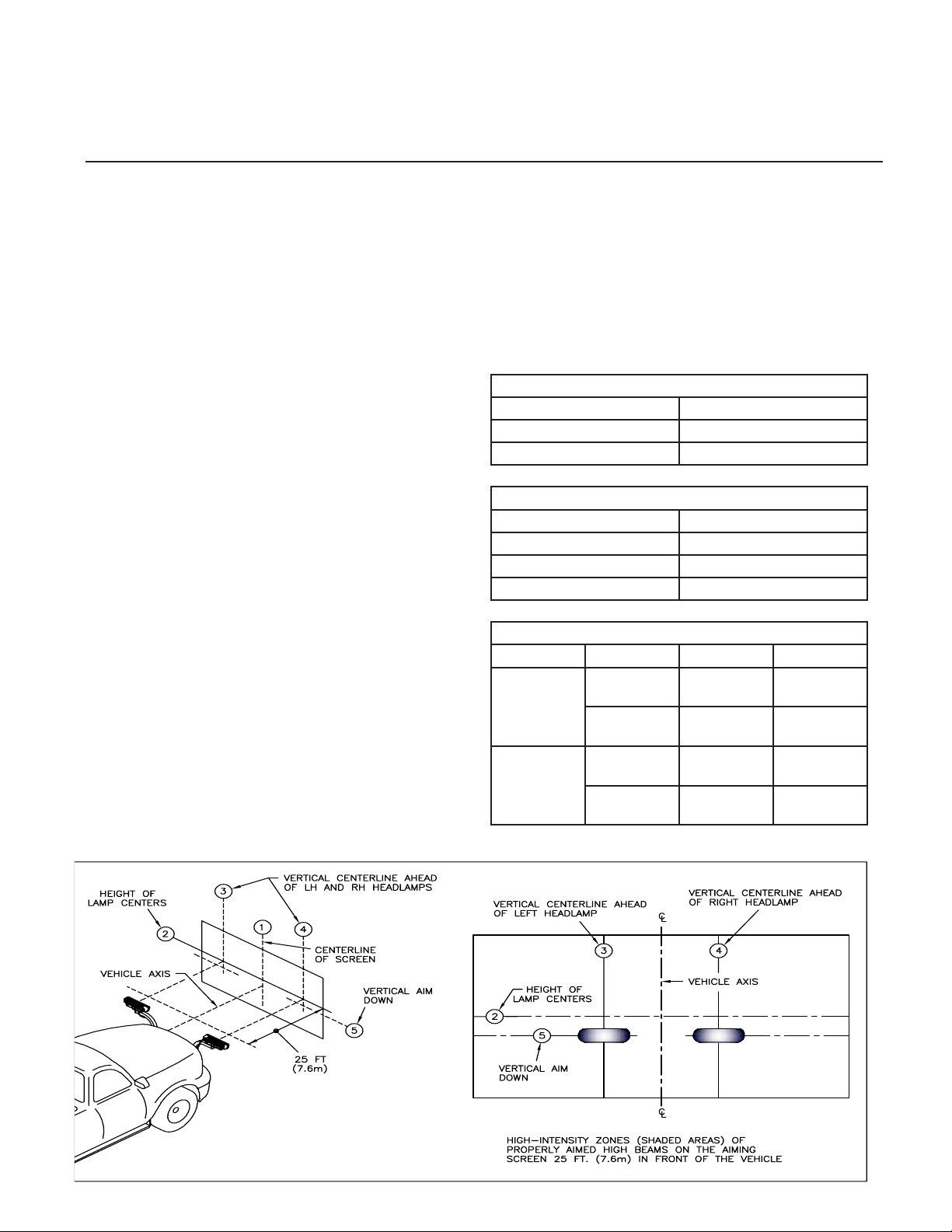
1. Park the vehicle with the plow attached on
a level surface 25’ (7.6 m) from a at, unob-
structed light-colored wall.
1. Centerline of vehicle.
2. Height of Lamp Centers.
3. LH Headlight Center (see Table 1 for di-
mensions from Line 1).
4. RH Headlight Center (see Table 1 for di-
mensions from Line 1).
5. Vertical Aim Down Height (see Table 2
for dimension from Line 2)
2. Mark the wall with black tape according to
drawing 5698B.
3. Wipe the lamp lenses clean and check for
proper switching and function.
4. Activate the plow lamp HIGH beams to illumi-
nate toward the wall.
5. Focus the center of the LH light beam on the
intersections of lines 3 and 5.
6. Focus the center of the RH light beam on the
intersections of lines 4 and 5.
7. Tighten the headlamp hardware according to
the table below.
Table 1: Lines 3 & 4 Dimensions
Type Line 3 & 4 Dimension
LED 19 in (48 cm)
Halogen 22 in (56 cm)
Table 2: Line Dimension
Height from Ground Dimension
22 to 36 in (56 to 90 cm) 0
36 to 48 in (90 to 120 cm) 2 in (5 cm)
48 to 54 in (120 to 140 cm) 4 in (6.4 cm)
Table 3: Hardware Torque
Type Size Ft-Lbs N-m
LED 1/2” (Bracket
to Bar)
58-82 79-112
1/4” (Light to
Bracket)
6-7 8-10
Halogen 1/2” (Bracket
to Bar)
58-82 79-112
3/8” (Light to
Bracket)
29-41 39-56
DWG NO. 5698B
Headlamp Aiming Procedure 13

HINIKER SNOWPLOW LIMITED WARRANTY
The only warranty Hiniker Company (Hiniker) gives and the only warranty that any Hiniker dealer is authorized to
give on behalf of Hiniker is as follows: (NO EMPLOYEE OR REPRESENTATIVE IS AUTHORIZED TO CHANGE
THIS WARRANTY IN ANY WAY OR GRANT ANY OTHER WARRANTY.)
Hiniker warrants to the original purchaser of a Hiniker snowplow that Hiniker will repair or replace any defects
in material and workmanship that occur within two years from date of retail delivery except the following items:
Hiniker warrants that it will repair or replace any defects in materials or workmanship with respect to the paint
nish, any accessories, and service parts and components for a period of one year from date of retail delivery.
Hiniker’s obligation and liability under this warranty is expressly limited to repairing or replacing, at Hiniker’s
option, at an authorized Hiniker dealer location, the defective parts at no charge to the original purchaser.
HINIKER MAKES NO OTHER WARRANTY, EXPRESS OR IMPLIED AND MAKES NO WARRANTY OF
MERCHANTABILITY OR OF FITNESS FOR ANY PARTICULAR PURPOSE.
HINIKER’S OBLIGATION UNDER THIS WARRANTY SHALL NOT INCLUDE ANY TRANSPORTATION
CHARGES TO OR FROM THE AUTHORIZED HINIKER DEALER LOCATION OR ANY LIABILITY FOR
INCIDENTAL, INDIRECT OR CONSEQUENTIAL DAMAGE OR DAMAGES OF ANY KIND FOR LOST PROFITS
OR DELAY. If requested by Hiniker, products or parts for which a warranty claim is made are to be returned freight
prepaid to our factory. Any improper use, operation beyond rated capacity, substitution of parts not approved by
Hiniker Company, or any alteration or repair in such manner as in our judgment a ects the product materially and
adversely shall void this warranty.
Hiniker reserves the right to make improvements or changes to any of it’s products without notice. Such
improvements or changes shall not trigger any obligation by Hiniker to update, modify or change any products
previously sold by Hiniker.
HINIKER does not warrant the following:
1. Used products.
2. Any product that has been repaired, modi ed or altered in a way not approved by Hiniker Company.
3. Depreciation or damage caused by normal wear, lack of reasonable and proper maintenance, failure
to follow Operators Manual Instructions, misuse, lack of proper protection during storage, or accident.
4. Parts replacement and service necessitated by normal wear or maintenance including, but not limited
to, cutting edges, hoses, snowplow skid shoes, blade marker guides and hardware.
5. Paint nish damage caused by normal wear.
Hiniker does not assume any liability for any damage to a motor vehicle resulting from the attachment or use of
a Hiniker snowplow. Compliance with applicable motor vehicle regulations is the responsibility of the installer.
Attachment of a Hiniker snowplow to a motor vehicle is at the risk of the purchaser.
It is the responsibility of the original snowplow purchaser to verify the original date of purchase.
A DELIVERY REPORT FORM must be lled out and received by Hiniker with 30 days of retail delivery at the
address below to initiate the warranty coverage.
HINIKER COMPANY
58766 240th Street
Mankato, MN 56001
PHONE 800-433-5620 -- FAX (507) 625-5883
www.hiniker.com
HINIKER WARRANTY
14 Warranty
This manual suits for next models
13
Table of contents
Other Hiniker Snow Blower manuals


Popular Snow Blower manuals by other brands


Ariens
Ariens Sno-Thro 920021 compact 24 Operator's manual

Buhler
Buhler Farm king FK311 owner's manual

Wiedenmann
Wiedenmann SNOW MASTER VARIO FLEX 3370 Series TRANSLATION OF ORIGINAL OPERATING INSTRUCTION

Craftsman
Craftsman 247.881720 Operator's manual

Poulan Pro
Poulan Pro PR5524ES owner's manual

MTD
MTD Yardworks 31AS33BE515 Operator's manual


