5
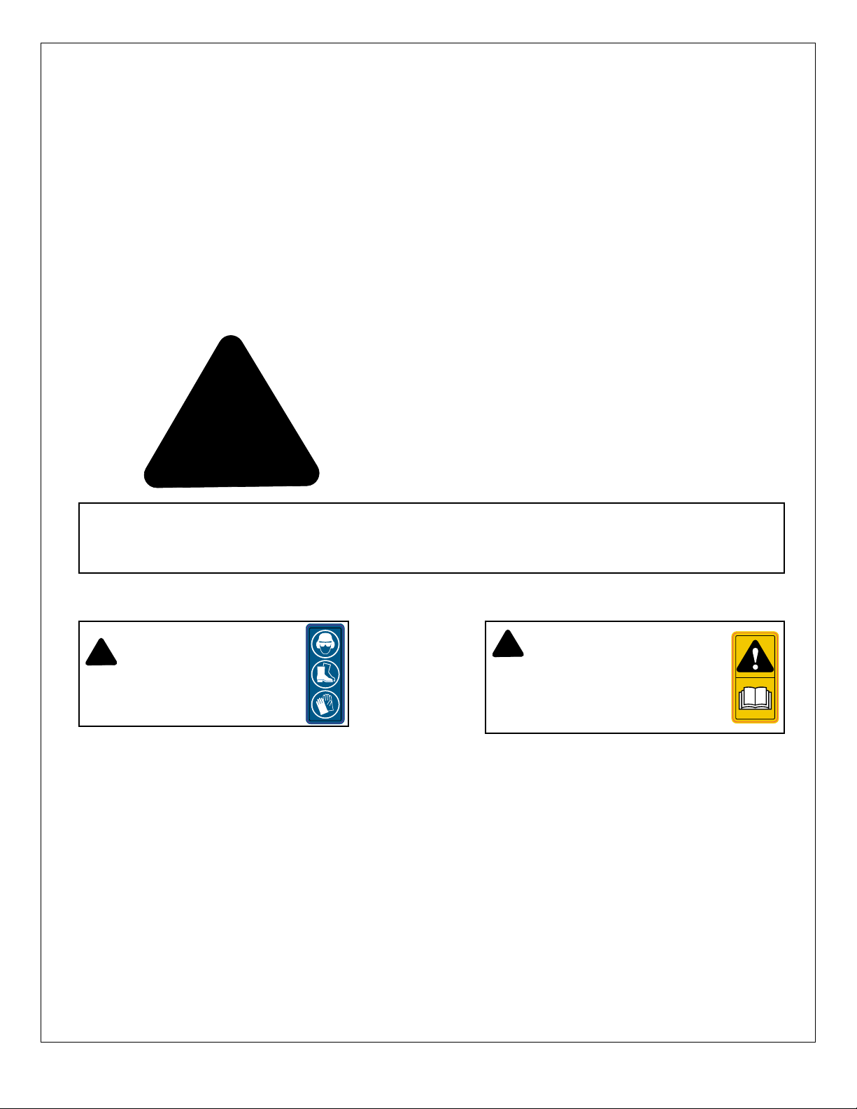
Safety labeling is an important part of the overall safe use of the snow blade. Safety labeling alerts and warns against
potential injury or death, and is important to follow these points to help keep your snow blade safe for you and others who
may be using it.
If labels need to be replaced:
• Be sure that the installation area is clean and dry.
• Be sure temperature is above 50°F (10°C).
• Determine exact position before you remove the backing paper.
• Remove the smallest portion of the split backing paper.
• Align the sign over the specied area and carefully press the small portion with the exposed sticky backing in place.
• Slowly peel back the remaining paper and carefully smooth the remaining portion of the sign in place.
• Small air pockets can be pierced with a pin and smoothed out using the piece of sign backing paper.
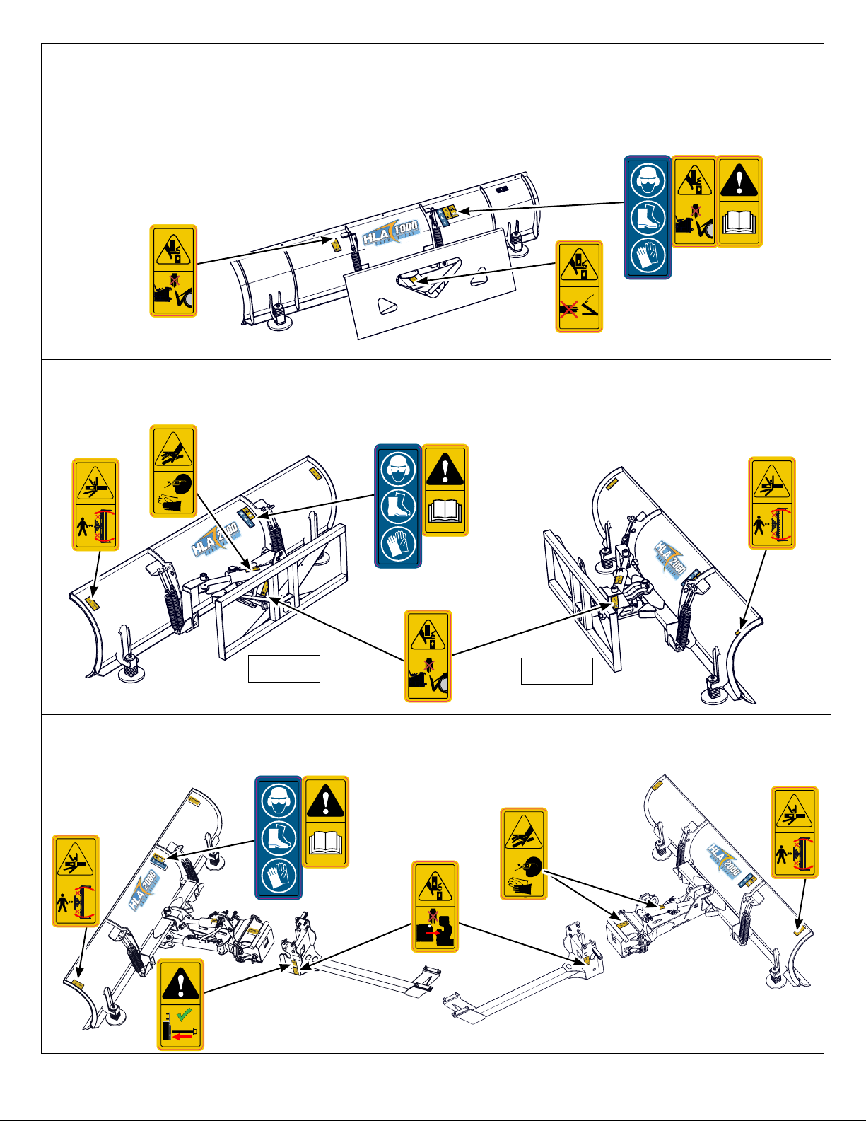
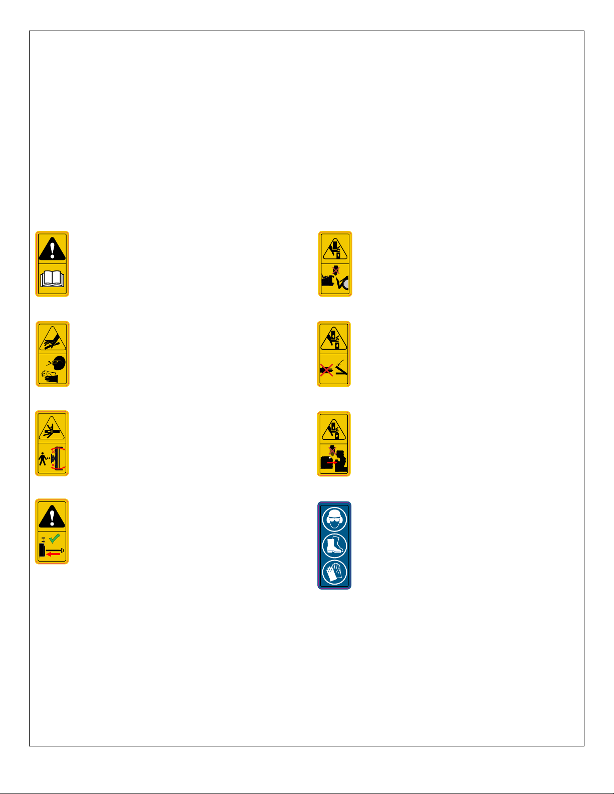
Safety Label Descriptions
• Keep safety signs clean and legible at all times.
• Replace safety signs that are missing or have become
illegible.
• Replaced parts that displayed a safety sign should
also display the current sign.
• Safety signs each have a part number displayed with
it. Use this part number when ordering replacement
labels.
• Safety signs are available from your authorized
distributor or the factory order desk.
SL00022
SL00004
SNL00001
Caution: read and understand ALL safety and
operating instructions in the manual, read
and understand ALL safety labels located on
the snow blade. The most important safety
device on this equipment is an informed SAFE
operator.
Caution: do not place your hand or any part
of your body on or near the front mount while
coupling to the power unit. Parts moving
together present a pinch point and may cause
serious injury Possible laceration, crushing,
amputation hazard. (HLA2DM models only)
Caution: Personal Protection Equipment (PPE)
is required when operating or maintaining this
snow blade. Failure to wear PPE will result in
personal injury.
Caution: Hydraulic uid is under pressure, be
aware that hydraulic leaks could develop with
out warning. . Do not check for leaks with your
hand or ngers while the system is pressurized,
serious injury could result. Possible burns or
poisoning from pressurized uid injection.
SL00015
Caution: Pivoting attachment, do not stand
around or between the attachment and the
power unit while the power unit is running.
Possible, crushing, collision hazard.
SL00021
SL00002
Caution: Moving parts present a potential pinch
hazard and could result in a serious injury. Use
caution and be aware of parts as they are being
moved or adjusted.
SL00028
SL00027
Caution: do not place your hand or any part
of your body on or near the front mount while
coupling to the power unit. Parts moving
together present a pinch point and may cause
serious injury Possible laceration, crushing,
amputation hazard. (Loader models only)
Caution: always ensure the front lock pin is
installed and secured. An unsecured snow
blade could slip out of the front mount assembly
and cause injury. Possible crushing hazard.
(HLA2DM models only)
Safety Label Descriptions