Hiniker 825 User manual

LIGHT TRUCK MATERIAL SPREADER
MODELS 825, 815, 625, 615
OPERATOR’S MANUAL
DO NOT USE OR OPERATE THIS EQUIPMENT UNTIL THIS MANUAL
HAS BEEN READ AND THOROUGHLY UNDERSTOOD
PART NUMBER 79202499 Rev. C


TABLE OF CONTENTS
TO THE PURCHASER.................................................................................................................. 2
SAFETY......................................................................................................................................... 3
OPERATING PROCEDURES .................................................................................................... 4-8
General Information................................................................................................................ 4
Sander Control Box................................................................................................................ 5
Spread Control ....................................................................................................................... 6
Swing Away Chute .............................................................................................................. 6-7
Storage................................................................................................................................... 8
MAINTENANCE & SERVICE PROCEDURES......................................................................... 9-13
General................................................................................................................................... 9
Chain Tension....................................................................................................................... 10
Throttle Control Actuator .......................................................................................................11
Lubrication....................................................................................................................... 11-12
Electric Clutch, Trouble Shooting Clutch Problems.............................................................. 13
INSTALLATION INSTRUCTIONS .......................................................................................... 14-15
OPTIONAL EQUIPMENT ....................................................................................................... 16-18
PARTS BREAKDOWN ........................................................................................................... 19-24
Engine Assembly.................................................................................................................. 19
Electrical Assembly .............................................................................................................. 20
Discharge Chute Assembly .................................................................................................. 21
Hopper Assembly ............................................................................................................ 22-23
Front Shaft & Apron Chain ................................................................................................... 24
SPECIFICATIONS....................................................................................................................... 25
ELECTRICAL SCHEMATIC DIAGRAM....................................................................................... 26
WARRANTY ................................................................................................................................ 27
Table of Contents 1
79202499 Rev. C 3/10 Hiniker/79202499RevC

TO THE PURCHASER
2 To The Purchaser
This product is designed and manufactured to
give years of dependable service, when prop-
erly maintained and used for the purpose for
which it is intended. Never allow anyone to op-
erate this equipment until they fully understand
the complete contents of this manual. It is the
responsibility of owners who do not operate this
equipment to ensure the operator is properly in-
structed and understands the contents of this
manual. It is also the owner’s responsibility to
ensure that anyone operating this equipment is
mentally and physically capable of so doing.
Important information is contained in this manu-
al to help ensure safe and efficient operation.
If you have any questions about this manual, or
the equipment discussed herein, contact your
Hiniker dealer.
This is the safety alert symbol. It alerts
an operator to information concerning
personal safety. Always observe and
heed these instructions, otherwise death, or
serious injury can result!
All references to LEFT or RIGHT mean viewing
the spreader from the rear and facing the truck.
This Operator’s manual is shipped with this
equipment. Contact your Hiniker dealer for ad-
ditional copies.
Always obtain original Hiniker service parts.
Substitute parts could adversely affect equip-
ment performance and warranty.
Check that your dealer has forwarded the
Hiniker delivery report copy and the machine
serial number to maintain maximum service and
warranty benefits. This does not put you on any
mailing list and information thereon is not avail-
able to others.
Your spreader’s identification number plate is at
the location shown below.
DWG. NO. 6018
Record the following information for later ref-
erence when obtaining service parts:
Purchase Date
Purchaser’s Name
Dealer’s Name
Machine Serial No.

This is the safety alert symbol. It alerts an
operator to information concerning per-
sonal safety. Always observe and heed
these instructions, otherwise death or serious
injury can result!
Operator safety is a principle concern in equipment
design and distribution. However, many accidents
occur because a few seconds of thought, and a more
careful approach to handling, were ignored.
Accidents can be avoided by knowing and following
the precautions cited in this manual.
GENERAL SAFETY
1. Read this manual thoroughly. Make sure the op-
erator understands it and knows how to operate
this equipment safely. This equipment can kill or
injure an untrained or careless operator and by-
standers. If you sell this equipment, ensure the
new owner acknowledges receipt of this manu-
al.
2. Make sure the engine cover is securely fastened
to the spreader before starting the engine and
operating the spreader.
3. Do not attempt to handle or service this equip-
ment, or direct others to do the same, unless
you know how to do it safely and have the prop-
er tools for the job.
4. Keep hands, feet, hair, and clothing away from
moving parts. Flying material can cause bodily
injury. Wear eye protection.
5. Do not alter the equipment to the extent of com-
promising safety or performance.
6. Material to be spread can be dangerous. Im-
proper selection, application, use or handling
may be a hazard to persons, vehicle or other
property. Follow instructions and precautions
given by the material manufacturer.
7. Do not over-load your vehicle beyond payload
limits. If there are any questions, contact the ve-
hicle manufacturer.
8. Do not use side extensions on your spreader to
increase salt storage capacity. Using side exten-
sions may damage hopper and cause injury to
personnel.
SAFETY
9. Do not drive motor vehicle with swing away
chute open or unlatched. Make sure swing away
chute is fully engaged in its working position or
damage to your spreader chute may occur.
10. Make sure the spreader is securely fastened to
the vehicle in accordance with this manual.
BEFORE OPERATION
1. Discipline yourself to visually check for worn,
damaged or cracked parts before starting use.
Replace these with genuine Hiniker parts.
2. Check all controls and operating functions of the
machine in a safe area before starting to work.
3. Do not lubricate, adjust or clean the machine
while it is running. After making adjustments,
check machine thoroughly for loose parts, hard-
ware and tools.
DURING OPERATION
1. Drive carefully and always wear seat belts when
operating a motor vehicle.
2. Ensure everyone is clear of the machine, espe-
cially away from blind areas of the operator, be-
fore starting or operating this equipment.
3. Stay out of hopper when conveyor power source
is engaged. If machine becomes blocked, do not
attempt to remove blockage until machine has
been shut off and conveyor and spinner move-
ment have stopped.
Use a shovel or other long-handled tool to reach
inside the hopper. Never attempt to break up
material inside the hopper with hands or feet.
4. Do not ride in any part of spreader while vehicle
is in motion.
5. Set the brakes and stop the truck’s engine be-
fore adjusting or servicing your spreader.
AFTER OPERATION
1. Inspect the spreader for components that have
become excessively worn or damaged and must
be repaired or replaced.
2. Develop a regular maintenance schedule to en-
sure safe, dependable spreader operation.
Safety 3

OPERATING PROCEDURES
GENERAL INFORMATION
Hiniker spreaders are capable of dispersing a
variety of dry materials for control of ice on road-
ways, walkways and parking lots.
Vehicle load carrying capacity limits the maxi-
mum load that can be safely transported, which
could be less than the volumetric capacity of the
spreader. Check the vehicle’s load rating certi-
cation sticker and DO NOT overload the vehicle
beyond its Gross Vehicle Weight Rating (GVWR)
or its Gross Axle Weight Rating (GAWR). Spread-
ers are recommended to be mounted on trucks
over 8,500 lb. GVWR.
Use the following tables to calculate vehicle pay-
load when material is loaded in the spreader.
VOLUMETRIC CAPACITY:
(Cubic Yards, Approx.)
LEVEL HEAPED
Standard 8’ Box 1.8 2.27
Standard 6 1/2’ Box 1.5 1.84
WEIGHT: (Pounds, Approx.)
8’ SS Standard Box 537
8’ Standard Box 602
6 1/2’ SS Standard Box 494
6 1/2’ Standard Box 550
Short Spinner Kit 33
Long Spinner Kit 42
Hinged Hopper Grids, 8’ Box 55
Hinged Hopper Grids, 6 1/2’ Box 45
Adjustable Inverted “V”, 8’ Box 26
Adjustable Inverted “V”, 6 1/2’ Box 20
MATERIAL WEIGHTS:
(Pounds Per Cubic Yard, Approx)
Very Coarse Rock Salt 950
Coarse Rock Salt 1,215
Coarse Sand - Dry 2,565
Coarse Sand - Wet 3,240
Calculate total material weight by multiplying
pounds per cubic yard by cubic yards of mate-
rial.
Local, state and federal regulations may require
flashing lights, center high mounted stop light,
or other additional equipment for operation on
public roadways. It is the owners responsibil-
ity to know and follow laws as they apply in his
area.
Always examine the spreader for worn or dam-
aged components prior to operation. During
operation, listen for unusual noise from the
spreader that might indicate component failure.
Never run a machine in need of repair.
Start the spreader for a short period of time be-
fore loading material to test for proper function
of moving parts.
After loading, run the spreader in an isolated
area, clear of people, to become familiar with
the controls and to verify the correct spread pat-
tern. Adjust deflectors on the discharge chute to
achieve the desired spread.
WARNING: Stop the conveyor and set
the vehicle parking brake before leav-
ing the vehicle to make adjustments.
If loading the hopper the night before an im-
pending snowfall or ice storm, park the spreader
indoors, if possible, to help prevent freeze-up of
material before morning.
4 Operating Procedures
Operating Procedures 5
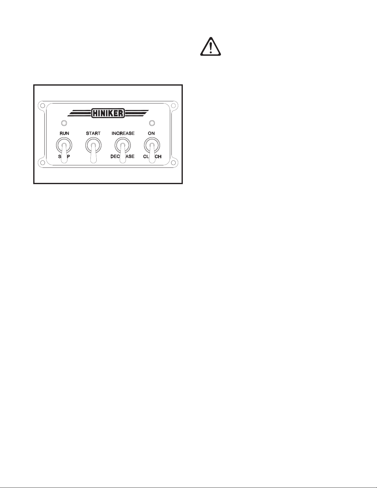
Sander Control Box
The spreader cab control consists of a power/
kill switch, a start switch, a throttle speed con-
trol switch, and a clutch on/off switch.
DWG. NO. 3184
Before starting the engine, check that the clutch
switch is in the OFF position.
To start the engine, first turn the power switch
to RUN, then hold the throttle control switch at
INCREASE for 3 seconds to choke the engine.
Hold the start switch at START until the engine
is running.
IMPORTANT: Do not hold the start switch
for longer than 15 seconds at a time when
attempting to start the engine. Allow the
starter motor to cool for 2 minutes between
attempts.
Once the engine has started, move the throttle
control switch to DECREASE until the engine
runs at the desired speed.
IMPORTANT: Prolonged operation of the en-
gine at full or partial choke may cause pre-
mature engine wear or failure due to gaso-
line diluted oil or fouled spark plug.
The engine can also be started by using the re-
coil starter with the power switch in the RUN
position.
CAUTION: If the battery has been re-
moved and machine is to be hand
started, be sure the positive cable
(red) at the battery end has the terminal
taped to prevent sparking to ground when
the engine is running.
The electric clutch can be engaged or disen-
gaged at any engine speed. However, since
engagement time and torque is almost instanta-
neous, to prevent premature spinner chain fail-
ure and chain tension loss, it is recommended
that the electric clutch be engaged at the lowest
possible engine speed without killing the en-
gine.
Burnishing the clutch is necessary to achieve
rated torque capacity. Never perform burnishing
while drive is loaded. New clutches and clutches
that have not been used for a long time, should
be burnished before full load operation by the
following procedure:
1. Rotate the clutch and check for rubbing or
interference. Reinstall chain, do not over
tighten.
2. Run at 50% throttle.
3. Engage and disengage the clutch 25 times.
(10 seconds on/10 seconds off).
4. Increase to 75% throttle.
5. Engage and disengage the clutch 25 times.
(10 seconds on/10 seconds off).
Disengage the clutch and move the power
switch to the STOP position when done using
the spreader.
6 Operating Procedures
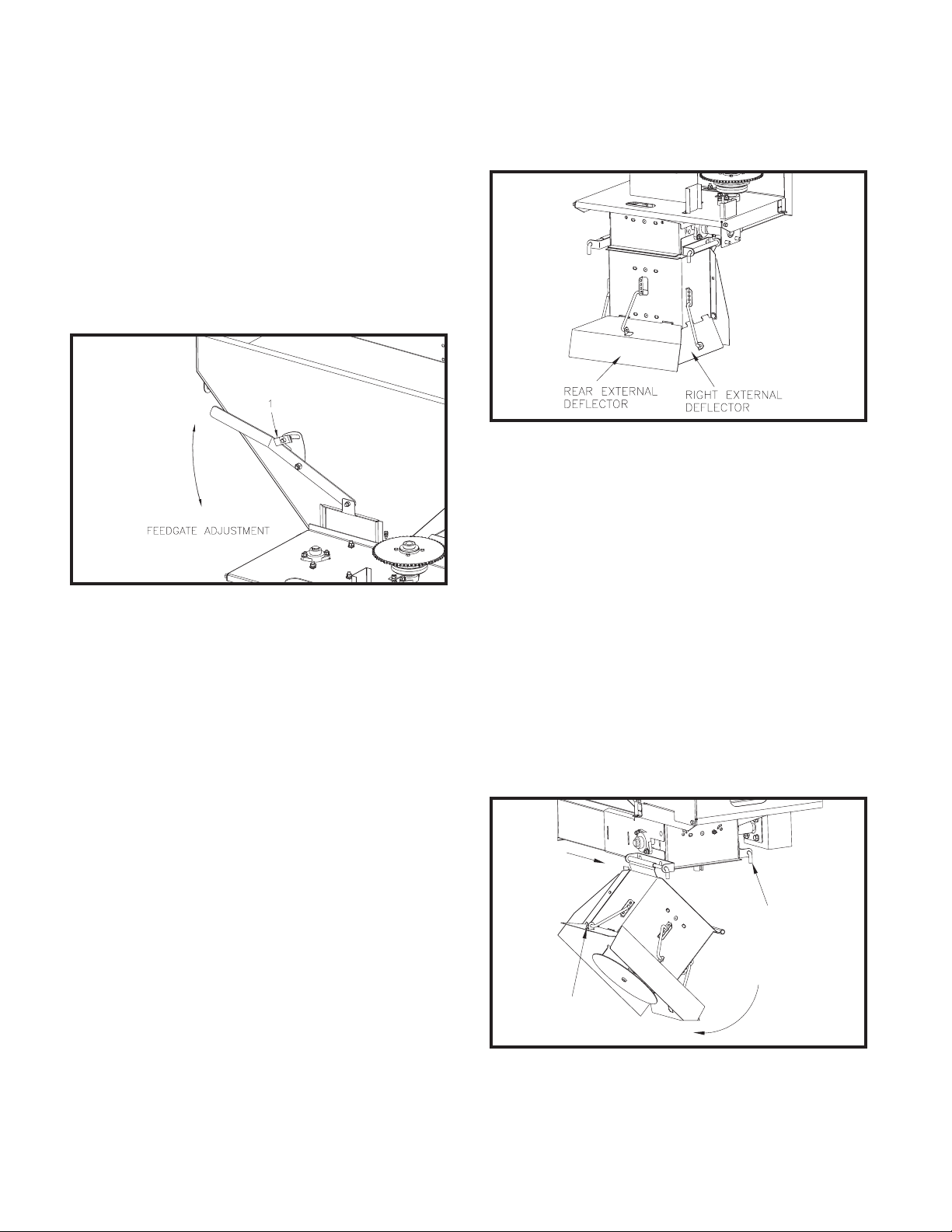
2. Deflector Positions:
The three external deflectors control the
size of the spread.
DWG. NO. 6020
Raising any of the three external deflectors
at the bottom of the discharge chute will pro-
duce a wider, thinner distribution of material to
that same side. Adjust the various speeds and
settings one at a time to produce the desired
spread pattern.
SWING AWAY CHUTE
Hiniker spreaders are equipped with a swing
away chute making cleaning of the hopper and
storage much easier. The swing away chute is
for clean out and storage only. Do not drive mo-
tor vehicle with swing away chute open or not
fully engaged in its working position.
SLIDE
REARWARD
1
2
DWG. NO. 6021
SPREAD CONTROL
Thickness of material cover is controlled by four
variables:
1. Feedgate Setting:
Raising or lowering the feedgate will in-
crease or decrease the amount of mate-
rial delivered to the spinner for any given
conveyor speed. Gate openings range from
3/8” to 4 1/4”.
DWG. NO. 6019
To set the feedgate position loosen the nut
at location 1. Use the feedgate handle to
move the feedgate into the desired posi-
tion. Lock the handle into position by re-
tightening the nut.
2. Conveyor Speed:
A faster conveyor speed will deliver more
material to the spinner.
3. Truck Speed:
The slower the vehicle travels, the more
material covers the ground.
4. Width of Spread:
A wide spread pattern produces a thinner
material cover.
Spread width is controlled by two variables:
1. Spinner Speed (determined by conveyor
speed):
A faster spinner speed produces a wider
pattern.

Operating Procedures 7
SHORT SPINNER OPERATION
To utilize this option pull the pin at location 1
and allow the chute to swing open. This disen-
gages the spinner from the spreader. The spin-
ner may need to be rotated slightly to fully dis-
engage the spinner. Slide the chute rearward
about 1 1/2 inches. Pull the hair pin cotter at
location 2. Disengage the deflector pin from the
hole in the deflector
DWG. NO. 6022
Rotate the chute assembly approximately 180
degrees. Insert the pin (arrow 1) from the exter-
nal deflector into the hole of the top chute mount
at location 2. Insert the hair pin cotter into the
pin behind the top chute mount to secure the
chute in this position.
DWG. NO. 6023
To realign the shafts for spreading, reverse the
above steps. When the chute has been secured
to the spreader, check that the coupler has fully
engaged the spring pin on the spinner shaft.
If it is not engaged turn the spinner shaft until
the spring pushes the coupler over the spinner
shaft and the coupler engages the spring pin.
A fully engaged spinner will look like the above
drawing.
SLIDE REARWARD
2
3
1
DWG. NO. 6024
LONG SPINNER OPERATION
To utilize this option pull the pin at location 1 and
allow the chute to swing open. This disengages
the spinner from the spreader. The spinner may
need to be rotated slightly to fully disengage the
spinner. Slide the chute rearward about 1 1/2
inches. Pull the (2) hair pin cotters at location 2.
Remove the left deflector pin from the chute as-
sembly. Insert one end of the pin into the hole in
the top chute mount at location 3. Insert the hair
pin cotter into the pin hole behind the top chute
mount to secure the pin in position.
DWG. NO. 6025
Rotate the chute assembly approximately 180
degrees. Insert the other end of the pin (arrow
1) from the external deflector into the formed
tab of the spinner assembly at location 2.

8 Operating Procedures
Insert the hair pin cotter to secure the chute as-
sembly in position.
To realign the shafts for spreading, reverse the
above steps. When the chute has been secured
to the spreader, check that the coupler has fully
engaged the spring pin on the spinner shaft. If
it is not engaged turn the spinner shaft until the
spring pushes the coupler over the spinner shaft
and the coupler engages the spring pin. A fully
engaged spinner will look like drawing 6023.
STORAGE
Store the spreader in a dry protected area when
it will not be used for an extended period of time.
Perform the following maintenance procedures
at the end of the season to ensure that the ma-
chine remains in good operating condition.
1. Disconnect and remove the battery from
the spreader. Apply a light coat of dielectric
grease to all electrical terminals, and cap or
tape loose terminals to prevent damage or
corrosion.
2. Wash the spreader to ush out any remain-
ing material.
3. Inspect for worn or damaged components.
Repair or replace as needed.
4. Grease all bearings. Grease points are
identied in the Maintenance & Service
section of this manual.
5. Oil conveyor and roller chains.
Maintain the spreader engine according to the
Briggs & Stratton owner’s manual that is shipped
with the spreader. Engine warranty is described
in the Briggs & Stratton manual.
If service or repair is required, contact an au-
thorized Briggs & Stratton service center. The
service center will ask for the model, type and
code number of the engine.
Locate the nearest service center in the “Yellow
Pages” or use the dealer locator at
www.briggsandstratton.com.

Maintenance & Service Procedures 9
MAINTENANCE & SERVICE PROCEDURES
Dependable spreader operation is the result of
following good maintenance procedures. Inspect
your spreader frequently to ensure that all parts
are working smoothly, and develop a schedule
for maintenance at required intervals.
GENERAL
Prior to operation of a new spreader, or one that
has been stored, inspect all hardware and verify
proper torque on all bolts and nuts in accordance
with the recommended torque specifications.
GRADE 5 TYPE B & F LOCKNUT TORQUES
Diameter Ft-lbs. N-m
1/4” 6-10 8-13
5/16” 13-18 17-25
3/8” 23-33 31-44
7/16” 38-54 51-73
1/2” 58-82 79-112
5/8” 117-165 158-223
3/4” 206-292 280-396
SET SCREW SEATING TORQUE
Socket
Head
Torque
In.-lbs.
(Ft-lbs)
Torque
N-m
#8
#10
1/4
5/16
20 (1.6)
36 (3)
87 (7.25)
165 (13.5)
2.25
4
9.8
18.6
Square
Head
#10
1/4
5/16
100 (8.8)
212 (17.7)
420 (35)
11.3
24
47.5
Loose bolts can cause hole elongation and part
failure resulting in dangerous operating condi-
tions and equipment breakdown.
Check all hardware periodically during opera-
tion and keep tightened to specified torques.
Replace worn bolts and locknuts with Grade 5
bolts and equivalent type B or F locknuts. Type
B locknuts are plain hex; type F locknuts are
flanged hex.
Fill electrical connectors with dielectric grease
to prevent corrosion of contacts when the con-
nectors are unplugged, and to make connecting
and disconnecting plugs easier.
Wash salt and dirt off the spreader before stor-
age.
Maintain the spreader engine according to the
Briggs & Stratton owner’s manual that is shipped
with the spreader. Engine warranty is described
in the Briggs & Stratton manual.
If service or repair is required, contact an au-
thorized Briggs & Stratton service center. The
service center will ask for the model, type and
code number of the engine.
Locate the nearest service center in the “Yellow
Pages” or use the dealer locator at
www.briggsandstratton.com
10 Maintenance & Service Procedures
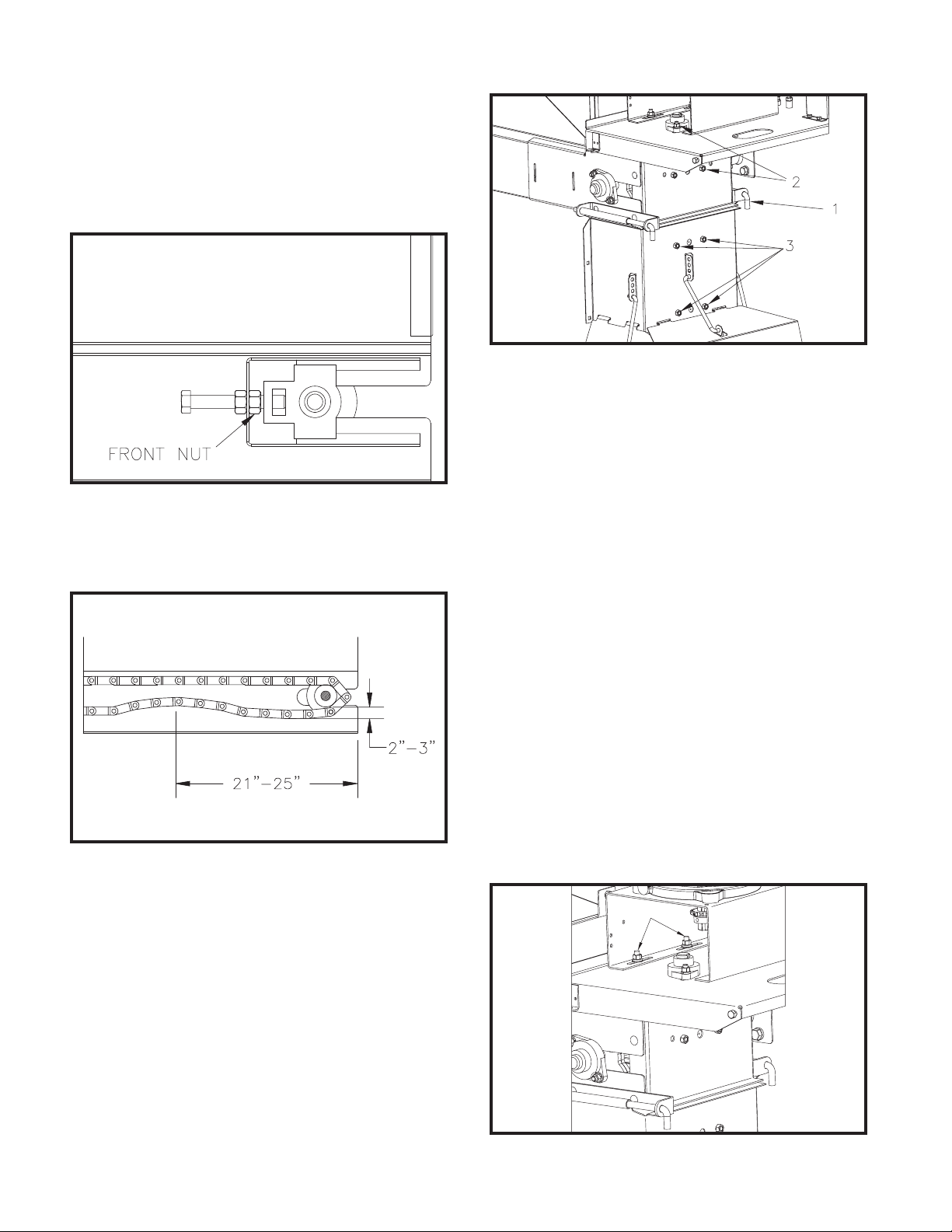
CHAIN TENSION
Tighten the conveyor chain periodically to com-
pensate for the chain stretching. Adjust both
sides the same amount to equalize the load on
the chain.
DWG. NO. 6026
Loosen the front nut, then turn the adjustment
bolt to take up the slack.
DWG. NO. 6596
Retighten the front nut after the chain is adjust-
ed. A properly tensioned chain can be pulled up
2-3 inches about 24 inches from the back of the
spreader side rails. A chain that is too tight will
cause excess stress on drive components.
DWG. NO. 6027
To adjust tension in the roller chain between the
gearbox and the spinner shaft first pull the pin at
location 1 and allow the spinner to swing open.
Loosen the (4) nuts, at location 2, that secure
the upper bearings which hold the upper spin-
ner shaft. Slide the top spinner shaft away from
the gearbox to tighten the chain. Make sure the
shaft is vertical before retightening the hard-
ware.
Rotate the chute assembly and reinsert the pin
at location 1. Loosen the (4) nuts, at location 3,
that secure the bearings which hold the bottom
spinner shaft. Slide the bottom shaft until it is
aligned with the top shaft.
When the shafts are aligned, the coupler on the
upper shaft will slide over the bottom shaft and
the spring pin will engage the slot in the cou-
pler. The bottom shaft may need to be rotated
slightly to align the slot in the coupler with the
spring pin. Make sure the bottom shaft is verti-
cal before retightening all hardware.
1
DWG. NO. 6028

Maintenance & Service Procedures 11
Tighten the engine drive chain by loosening the
four nuts (arrow 1)holding the engine plate, then
slide the entire engine assembly. Retighten nuts
to secure the engine plate
THROTTLE CONTROL ACTUATOR
Reassemble the throttle actuator as follows:
FORWARD
1
2
3
DWG. NO. 6040
1. Assemble the actuator on the bracket.
2. Advance the actuator arm (arrow 1) forward
with a 9V battery until the arm is stopped
by the bracket.
3. Place the plastic block (arrow 2) on the ac-
tuator arm and loosely bolt the bracket (ar-
row 3) on the engine plate.
4. Slide the governor control rack on the en-
gine fully ahead, then pin to the plastic
block.
5. Fully tighten the bracket to the engine
plate.
6. Cycle the actuator to verify that the arm is
stopped by the bracket, not by the engine
mechanism.
LUBRICATION
CAUTION: Do not lubricate, adjust or
clean the machine while it is running.
Death or serious injury can result.
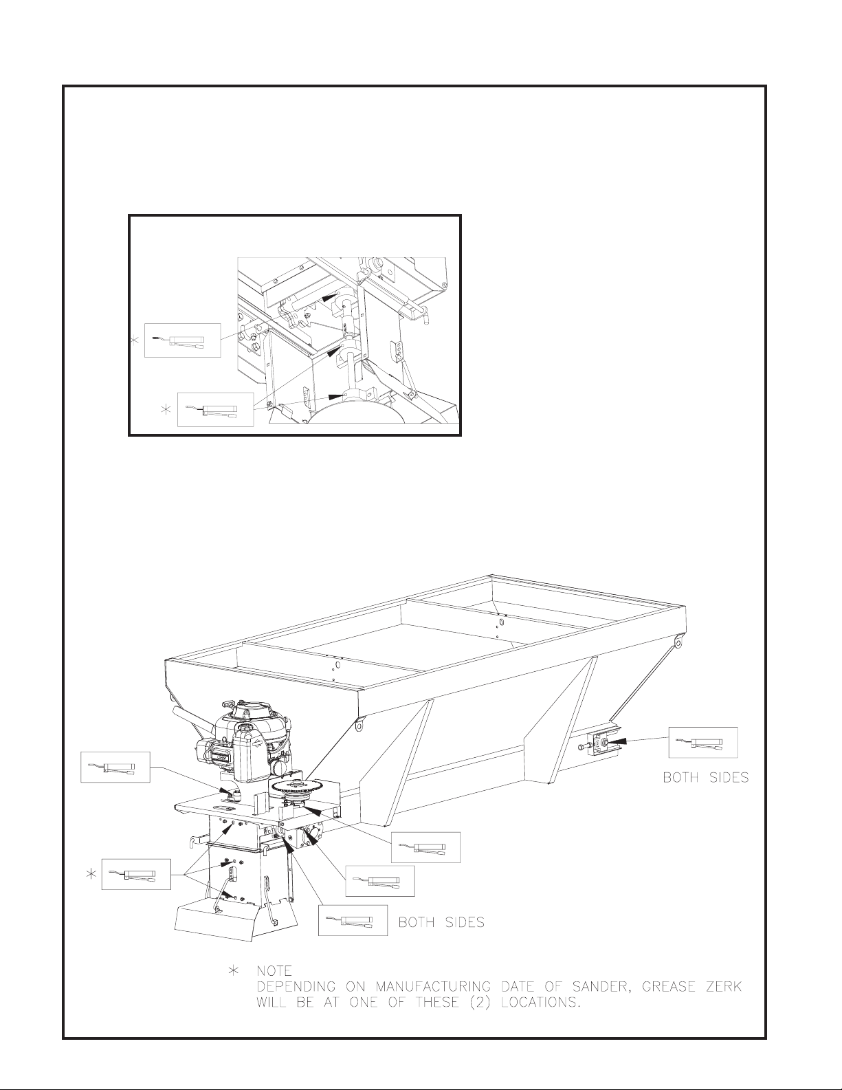
Prior to operation of a new machine, or one that
has been stored, grease all bearing points with
a high quality SAE multi-purpose grease and oil
the roller chains.
Throughout the season, grease bearings at
about 10 hour intervals and oil roller chains of-
ten.
NOTE: Over-greasing may cause seal damage
to bearings. Use only one pump of grease per
fitting.
Replace gear box oil annually with SAE 90 gear
lubricant. Prevent debris from entering the gear
box by cleaning dirt from plug area and wiping
plugs prior to reinstallation.
DWG. NO. 6031
Remove the drain plug at location 1 to drain old
oil into a quart or larger container and discard.
Reinstall the drain plug and remove the breath-
er at location 2 and the oil level plug at location
3. Fill the gearbox through the breather port un-
til oil appears at the level port. Reinstall the oil
level plug, add another 1/4 quart then reinstall
the breather. Capacity is about 5/8 quart (0.6
liters).
12 Maintenance & Service Procedures
GREASE POINT LOCATIONS
DWG. NO. 6029
DWG. NO. 6030
Spinner Grease Point Locations

Maintenance & Service Procedures 13
ELECTRIC CLUTCH
The following procedures are recommended to
maximize the life of the electric clutch:
- Remove and clean the electric clutch at
the end of the snow season.
- After cleaning the clutch, coat both mat-
ing surfaces with oil or light grease.
- Remove oil and grease before using the
clutch the following season.
DWG. NO. 6041
When servicing worn clutch components, the
rotor and armature must be replaced as a pair.
TROUBLESHOOTING CLUTCH PROBLEMS
A. Symptom: Clutch will not Engage
PROBLEM POSSIBLE CAUSES
- Low voltage
supply
- Zero voltage
- Defective battery
- Faulty charging system
- Bad wiring or connectors
- Broken lead wire
- Open clutch coil, check
coil resistance
- Faulty switch
B. Symptom: Noisy Clutch
PROBLEM POSSIBLE CAUSES
- Failed bearing
- Adapter plate
rattles against
antirotation pin
- Loose mounting
- Operating Temperature
above 250OF
- Bearing Preloaded Axi-
ally
- Some noise is normal: to
reduce noise level, iso-
late antirotation pin from
frame with rubber.
C. Symptom: Clutch Slips
PROBLEM POSSIBLE CAUSES
- Low voltage
supply
- Contaminat-
ed friction
surfaces
- Clutch loose
on shaft
- Clutch not
mounted
square
- Broken rivet
joints
- Defective battery
- Faulty charging system
- Bad wiring or connectors
- Oil or grease on clutch
- Eccentric collar not locked
onto the shaft
- Mounting shoulder not
square
- Clutch integral key hitting
end of keyway
- Loose mounting
Replace clutch

14 Installation Instructions
GRADE 5 TYPE B & F LOCKNUT TORQUES
Diameter Ft-lbs. N-m
1/4” 6-10 8-13
5/16” 13-18 17-25
3/8” 23-33 31-44
7/16” 38-54 51-73
1/2” 58-82 79-112
5/8” 117-165 158-223
3/4” 206-292 280-396
SET SCREW SEATING TORQUE
Socket
Head
Torque
In.-lbs.
(Ft-lbs)
Torque
N-m
#8
#10
1/4
5/16
20 (1.6)
36 (3)
87 (7.25)
165 (13.5)
2.25
4
9.8
18.6
Square
Head
#10
1/4
5/16
100 (8.8)
212 (17.7)
420 (35)
11.3
24
47.5
MOUNTING THE SPREADER
1. Remove the tailgate from the truck according
to instructions from the vehicle manufacturer.
WARNING: Never attempt to lift a
spreader with material in the hopper.
Verify that the lifting device is capable
of handling at least 1,000 LB. loads before try-
ing to lift the spreader.
2. Lift the spreader by hooking the slot in the
rear-most (toward rear of the truck) hopper
cross member.
The lifting slot is placed at the approximate
balance point of the spreader. Residual mate-
rial, gasoline, oil, battery, top screen, inverted
vee may affect this balance point.
INSTALLATION INSTRUCTIONS
3. Center the spreader on the truck with the
rear rails extending about 12-14 inches be-
hind the furthest point of interference (back
of the truck, bumper, trailer hitch, etc.) Verify
the rear legs of the spreader rest securely
on the bed of the truck.
Place lumber as needed between the back
of the truck cab and the front of the spread-
er to help hold the sander in position and
protect the truck from damage due to shift-
ing of the spreader.
4. Attach the sander to the truck bed using 3/8”
hardware through the slot in the sanders (4)
legs. Ratchet tie-down straps must be used
to secure the spreaders (4) tie down eyes
located at each corner of the spreader to
the vehicles factory installed anchor points.
Ratchet tie down straps must be used to
properly secure hopper to vehicle. Do not
use cam buckle or other forms of straps
where adequate tension to secure hopper
against load shifting cannot be achieved.
NOTE: Inspect hold-downs and tie down straps
periodically for wear or loosening, and retighten
or repair as required.
Installation Instructions 15
CHUTE ASSEMBLY
DWG. NO. 6032
1. Attach the chute assembly to the spreader
by inserting the long pin through the clevis
and chute hinge at location 1.
Rotate the chute assembly and insert the
pin at location 2. Check and see if the two
shafts are aligned. The slot on the coupler
should be pointing toward the side of the
machine for ease of assembly.
When the shafts are aligned the coupler on
the upper shaft will slide over the bottom
shaft and the spring pin, at location 3, will
engage the slot in the coupler. The bottom
shaft may need to be rotated slightly to align
the slot in the coupler with the spring pin.
2. If the shafts are not aligned, loosen the (4)
nuts at location 4 holding the lower spinner
shaft bearings to the chute. Slide the bot-
tom shaft until it is aligned with the top shaft
and the coupler engages the spinner shaft
spring pin.
Again, when the shafts are aligned, the cou-
pler on the upper shaft will slide over the
bottom shaft and the spring pin will engage
the slot in the coupler. The bottom shaft
may need to be rotated slightly to align the
slot in the coupler with the spring pin.
Check that the bottom shaft is vertical be-
fore retightening all hardware.
INSTALLATION OF
CAB CONTROL & ELECTRICAL WIRING
Use the bracket and hardware provided to
mount the cab control box at a convenient loca-
tion for the operator.
Connect the extension cable to the engine har-
ness. Route the extension cable along the RH
side of the hopper.
Determine the best location for running the ex-
tension cable into the truck cab. If a hole must
be drilled to pass the cable through the cab wall,
protect wires from sharp edges around the hole
with a grommet.
Connect the cab control box cable to the exten-
sion cable for operation of the spreader.

16 Optional Equipment
OPTIONAL EQUIPMENT
REF.
NO.
PART
NUMBER DESCRIPTION QTY.
REF.
NO.
PART
NUMBER DESCRIPTION QTY.
1
2
79201998
79202566
79202135
79202567
400-15052
79202565
Inverted V, 8’ Hopper
Inverted V, 8’ Hopper SS
Inverted V, 6 1/2’ Hopper
Inverted V, 6 1/2’ Hopper SS
Strap
Strap SS
1
1
1
1
2
2
3
4
5
950-001-089
031-09103
951-005-003
951-003-013
79202743
79202744
Hex Head Cap Screw 3/8-16 x 3/4
Hex Head Cap Screw 3/8-16 x 3/4 SS
Lock Nut 3/8-16 Nylon Insert
Lock Nut 3/8-16 Nylon Insert SS
Inverted V Gusset
Inverted V Gusset SS
12
12
12
12
2
2
DWG. NO. 6305
Adjustable Inverted V Kit No. 79202394 6 1/2 FT. Hopper, SS
Adjustable Inverted V Kit No. 79202042 8 FT. Hopper
Adjustable Inverted V Kit No. 79202395 8 FT. Hopper, SS
Inverted V Options

Optional Equipment 17
HINGED HOPPER GRIDS OPTION
DWG. NO. 6015
79202391 Hinged Hopper Grids Kit, 6 1/2 Ft. Hopper
79202392 Hinged Hopper Grids Kit, 8 Ft. Hopper
REF.
NO.
PART
NUMBER DESCRIPTION QTY.
REF.
NO.
PART
NUMBER DESCRIPTION QTY.
1
2
3
79202561
79202562
79202009
950-001-113
Screen, 8 Ft. Hopper
Screen, 6 1/2 Ft. Hopper
Screen Holdown
Hex Head Cap Screw 5/16-18 x 3/4 Gr. 5
2
2
2
6
4
5
6
7
951-005-036
79203146
950-001-089
951-002-003
Lock Nut 5/16-18 Mac Lock
Middle Grid Support
Hex Head Cap Screw 3/8-16 x 3/4 Gr. 5
Whiz Lock Nut 3/8-16
6
1
2
2
TARP KIT
DWG. NO. 6460
79203036 6 1/2 Foot Sander Tarp Assembly
79203037 8 Foot Sander Tarp Assembly
REF.
NO.
PART
NUMBER DESCRIPTION QTY. REF.
NO.
PART
NUMBER DESCRIPTION QTY.
1
2
3
79203033
79203032
79203031
79203029
Tarp Shurco 8’ Sander
Tarp Shurco 6 1/2’ Sander
Tarp Hook
LH Tarp Bracket
1
1
4
4
4
5
6
7
79203030
030-16041
033-12007
951-005-036
RH Tarp Bracket
Carriage Bolt 5/16-18 x 3/4 Gr. 5
SAE Flat Washer 5/16 Inch
Mac Lock Nut 5/16-18
4
4
4
4
18 Optional Equipment
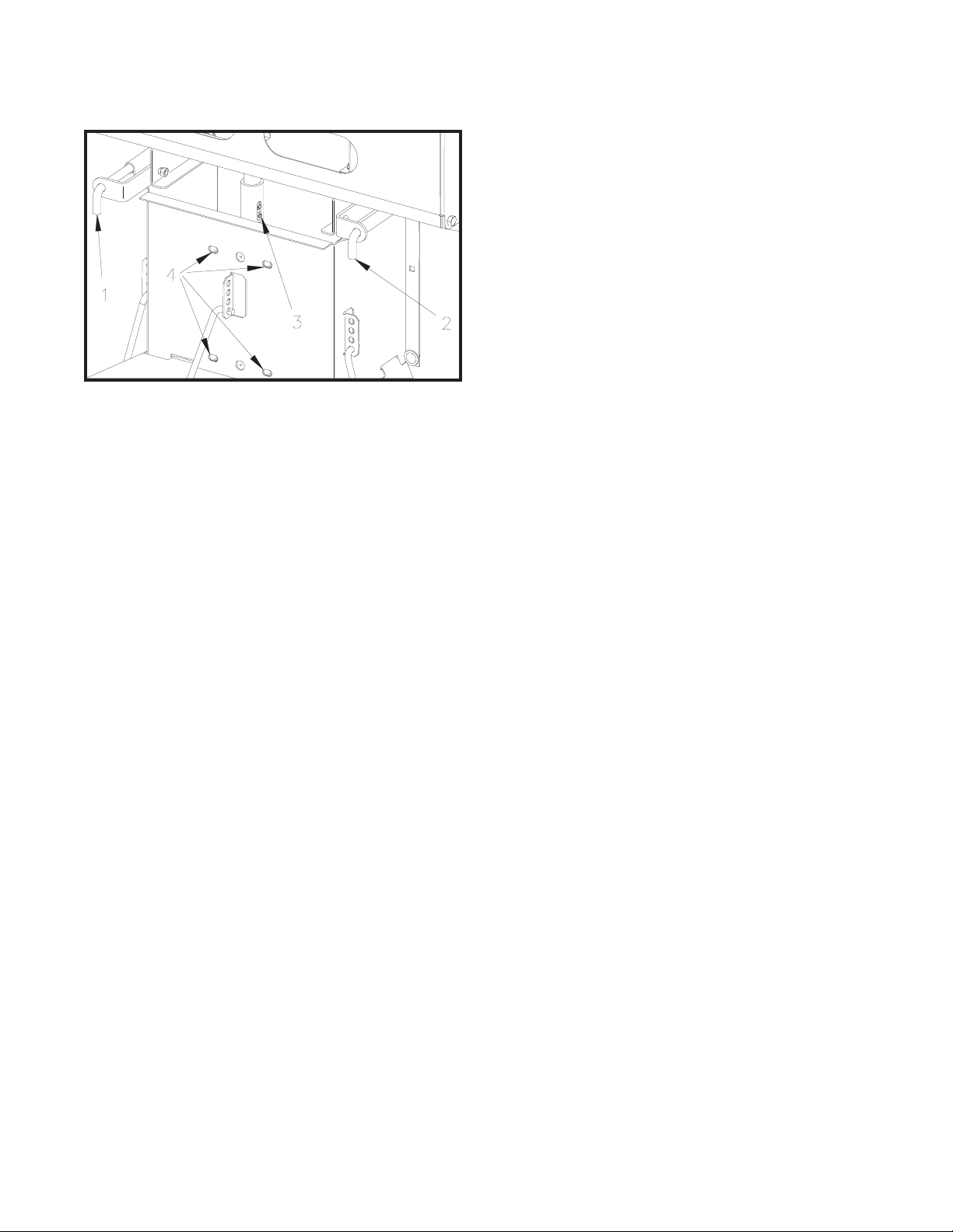
TIE DOWN KIT
DWG. NO. 603979202393 Truck Hold Down Kit
REF.
NO.
PART
NUMBER DESCRIPTION QTY. REF.
NO.
PART
NUMBER DESCRIPTION QTY.
1 79202400 Ratchet Tiedown 4
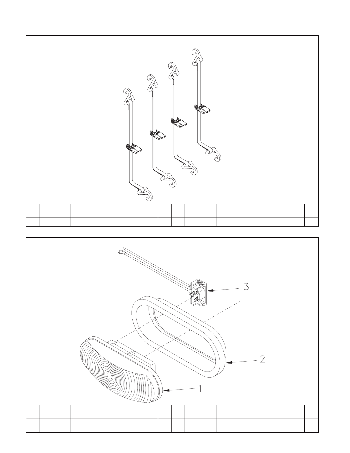
BRAKE LIGHT KIT
DWG. NO. 367479202581 Brake Light Assembly
REF.
NO.
PART
NUMBER DESCRIPTION QTY. REF.
NO.
PART
NUMBER DESCRIPTION QTY.
1
2
79202091
79202092
Lamp
Grommet
1
1
3 79202093
79202089
Plug
Brake Light Assembly
1
This manual suits for next models
3
Table of contents
Other Hiniker Spreader manuals

Popular Spreader manuals by other brands


Gardena
Gardena Spreader L operating instructions

Brinly
Brinly PS10-70BH owner's manual

Earth Way
Earth Way 2600A-Plus Estate Assembly and operating instructions

Tube-Line
Tube-Line NITRO 575RS Operator's manual

Earth Way
Earth Way EV-N-SPRED C24HD Assembly and operating instructions

AIRFLO
AIRFLO PSV Operator and parts manual