AIRFLO PSV Product manual

365 UPPER OAKWOOD AVE, ELMIRA HEIGHTS, NY 14903
PHONE: 607-722-8284 / FAX: 607-733-8397
OPERATOR AND
PARTS MANUAL
PSV
PICK-UP SPREADER

September 11, 2014 [AIR-FLO MANUFACTURING CO., INC.]
PSV PICK
-
UP SPREADER OPERATOR AND PARTS MANUAL
|
1
PSV PICK-UP SPREADER
OPERATOR AND PARTS MANUAL
TABLE OF CONTENTS:
CHECKLIST…………………………………………………………………….PAGE 2
GENERAL INFORMATION……………………………………………….PAGES 2-3
SAFETY AND WARNING INFORMATION:
SAFETY PROCEDURES………………………………................PAGES 3-4
SAFETY DECALS………………………………………………………PAGE 4
SAFETY DECAL LOCATION………………………………………….PAGE 4
INSTALLATION INSTRUCTIONS………………………………………..PAGES 5-8
SPREADER OPERATION……………………………………………….PAGES 8-11
SPREADER MAINTENANCE………………………………………….PAGES 11-12
PARTS LISTING………………………………………………………...PAGES 13-24
WARRANTY…………………………………………………………………..PAGE 25

September 11, 2014 [AIR-FLO MANUFACTURING CO., INC.]
PSV PICK
-
UP SPREADER OPERATOR AND PARTS MANUAL
|
2
PRE-USE CHECKLIST:
ÿRead this entire Owner’s Manual before operating this spreader. This
includes the Briggs and Stratton engine Owner’s Manual.
ÿBefore loading and operating and operating the sander, check the
recommended maximum payload. DO NOT OVERLOAD THE SANDER!
ÿRead and understand all of the safety decals located on the spreader.
(Ex. CAUTION, WARNING, and DANGER signs)
ÿBefore starting your spreader, check and verify that the engine crankcase
and associated gearbox are filled to the proper levels of lubricant. Verify
that the lubricant viscosities meet your requirements.
ÿVerify that the engine cover is securely fastened to the spreader before
operating.
ÿVerify that all personnel are clear of the spray area before starting or
operating this spreader.
ÿVerify that the spreader is securely fastened to the vehicle in accordance
with this manual.
GENERAL INFORMATION:
The purpose of this manual is to assist the owner/operator in maintaining and operating the
Air-Flo PSV-8 Pick-Up Spreader. Read it carefully before attempting operation,
maintenance, or repair
VEHICLE REQUIREMENTS:
¾ or 1 ton pick-up above 8500 # GVWR
CAUTION! Do not overload vehicle beyond GVWR or GAWR. Check the vehicle’s load
rating certification sticker for maximum vehicle capacity.

September 11, 2014 [AIR-FLO MANUFACTURING CO., INC.]
PSV PICK
-
UP SPREADER OPERATOR AND PARTS MANUAL
|
3
SPREADER AND MATERIAL WEIGHTS:
MATERIAL WEIGHT (POUNDS PER CUBIC YARD)
PSV-8 650 LBS.
#1 ROCK SALT 950 LBS.
#2 ROCK SALT 1,215 LBS.
COARSE SAND - DRY 2,565 LBS.
COARSE SAND - WET 3,240 LBS.
SAFETY:
WARNING! Observe the following Safety Precautions before, during, and after
operating this spreader. By following these precautions and utilizing common sense;
possible injury to personnel and potential damage to this machine may be avoided.
1.) Personnel who install, mount, operate, or service this equipment must be properly
instructed and informed.
2.) Read operator manuals completely before operating equipment.
3.) Read decal instructions, cautions, and warnings prior to interacting with equipment
4.) Check spreader to ensure that all shields, safety guards, and grates are in place
prior to operating
5.) Use care when mounting and dismounting
6.) The moving components (Ex. drive shafts, conveyers, spinner assemblies, etc.)
transmit high amounts of power, are hazardous when in operation. All maintenance,
inspections, or operator adjustments must be made when all power is off.
(Ex. cleaning, oiling, unclogging material jambs, etc.)
7.) Keep spreader and surrounding area clear of personnel and property when
operating.
8.) Keep spreader unit and components in proper working condition. Replace missing or
damaged safety signs.
9.) Unauthorized modifications to the spreader and related components may impair the
function and /or safety of the device.

September 11, 2014 [AIR-FLO MANUFACTURING CO., INC.]
PSV PICK
-
UP SPREADER OPERATOR AND PARTS MANUAL
|
4
10.) Keep all loose clothing, hair, jewelry, and limbs clear of the spreader before starting
or operating this device.
11.) Do not climb on or in the spreader during operations. Do not ride on the spreader
while the vehicle is in motion.
12.) Do not operate a spreader that is in need of maintenance and repair.
SAFETY DECALS AND LOCATIONS:

September 11, 2014 [AIR-FLO MANUFACTURING CO., INC.]
PSV PICK
-
UP SPREADER OPERATOR AND PARTS MANUAL
|
5
INSTALLATION INSTRUCTIONS:
STEP 1:
BEFORE INSTALLING PSV,
BOLT (2) 2”X 4”BOARDS TO PRE-EXISTING
HOLES IN BOTTOM OF HOPPER SIDE
GUSSETS ON BOTH SIDES OF THE BODY
FIGURE #1

September 11, 2014 [AIR-FLO MANUFACTURING CO., INC.]
PSV PICK
-
UP SPREADER OPERATOR AND PARTS MANUAL
|
6
STEP 2:
USE THE (4) PRE-EXISTING TIE DOWN HOOKS TO
SECURE THE PSV TO THE TRUCK BED
FIGURE
#2

September 11, 2014 [AIR-FLO MANUFACTURING CO., INC.]
PSV PICK
-
UP SPREADER OPERATOR AND PARTS MANUAL
|
7
INSTALLATION INSTRUCTIONS:
1.) Mounting the spreader onto the vehicle:
a.) Install inverted “v”in spreader with the bolts provided
b.) Remove the tailgate from the vehicle
c.) Lift the spreader by means of the square knock-out in the rear most hopper
cross member. (toward the rear of the truck)
WARNING! The lifting device must be adequately rated to lift a payload equal
to or greater than the spreader weight.
d.) Elevate the spreader off the vehicle with lumber. Place lumber under the side
gussets of the spreader. (This will help remove the excess material that
accumulates under the spreader-refer to Figure 1)
e.) Center the spreader on the vehicle with the ends of the rails 14”to the rear of
the nearest vertical obstruction (bumper, trailer hitch, etc.). It is recommended
that the spinner/chute assembly be loosely attached to the hopper. This
should be done to avoid any interference between the vehicle and the
spinner/chute assembly.
f.) Bolt the spreader to the vehicle frame using the holes located in each corner
of the (4) ratchet style tie down straps included with the spreader.
g.) Secure the spreader to the vehicle using the four (4) tie-down eyes located at
each corner of the spreader to the vehicle’s factory installed anchor points.
(Using the four (4) ratchet style tie-down straps included with the spreader)
WARNING! The tie-down straps provided with the spreader are intended only
to supplement the tie down of the spreader to the vehicle. The spreader must
be securely fastened to the frame of the vehicle as well.
Notes:
Verify with the vehicle’s manufacturer that the factory installed anchor points are designed
for this application
Periodically check that the spreader mounting hardware is securely tightened

September 11, 2014 [AIR-FLO MANUFACTURING CO., INC.]
PSV PICK
-
UP SPREADER OPERATOR AND PARTS MANUAL
|
8
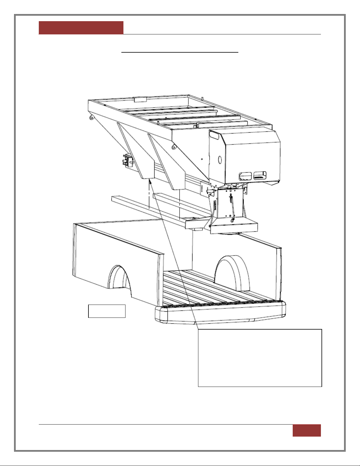
2.) Mounting the Spinner/Chute Assembly
a.) Attach the spinner/chute assembly to the spreader using the four (4)
3/8-16 X 5/8”hex head bolts, lock washers, and nuts. The head of the bolt is
to be placed on the inside of the chute assembly. Push the chute assembly
towards the cab of the vehicle. Loosely attach the hardware, but do not
tighten at this time.
b.) Install the roller chain between the sprocket mounted to the spinner/chute
assembly and the gearbox sprocket. Make sure both sprockets are in line with
one another. Tighten the gearbox sprocket set screw. Install the roller chain
master link.
c.) To adjust the roller chain tension, loosen the spinner shaft bearing bolts and
slide the shaft away from the gearbox sprocket. Be sure to maintain the
vertical alignment of the spinner shaft and the bearings before tightening the
hardware. The correct chain tension should allow for a 5/16”deflection
midway between both chain sprockets.
CAUTION! Do not over-tighten the chain tension. This can cause damage to
the chain, bearings, and gearbox.
d.) Install the chain guard using the three (3) 1/4-20 X 3/4”hex head bolts, lock
washers, and nuts
e.) Tighten all hardware to the recommended torque specifications as shown in
this manual.
SPREADER OPERATION:
NOTE: Before starting engine, follow all safety precautions.
1.) Control Panel Description:
a.) The clutch switch is a three position switch with the following functions:
1. “OFF”Position: While this switch is in this position and the engine is running,
the spreader feed chain and the spinner disk will remain non-operational.
(Meaning the ice control material will not be dispensed)
2. “ON”Position: While this switch is in this position and the engine is running,
the spreader feed chain and the spinner disk will dispense the ice control
material at the normal regulated rate.

September 11, 2014 [AIR-FLO MANUFACTURING CO., INC.]
PSV PICK
-
UP SPREADER OPERATOR AND PARTS MANUAL
|
9
3. “BLAST”Position: While this switch is in this position and the engine is
running, the spreader feed chain and the spinner disk will dispense the ice
control material at a higher rate. (note: in order to use this option, the switch
must be held in this position. It cannot be toggled like the “ON”or “OFF”
options)
b.) The ignition switch is a three position switch with the following functions:
1. “OFF”Position: While in this position, 12 VDC power is shut off to the
spreader. (Note: to turn off the spreader, toggle switch to “OFF”
position.)
2. “ON”Position: While in this position, 12 VDC power is turned on to the
spreader.
3. “START”Position: While in this position, the spreader’s engine starter is
activated.
c.) The throttle switch is a two position switch with the following functions:
1. “CHOKE/FAST”Position: While in this position, the engine speed will
increase
2. “IDLE”Position: While in this position, the engine speed will decrease
2.) Starting the Engine:
a.) Verify that the clutch switch and ignition switch on the cab control panel are in the
“OFF”position.
b.) Turn the spreader ignition switch to the “ON”position
c.) Move the throttle switch on the cab control panel to the “IDLE”position, and hold
for approximately two seconds.
d.) Turn the ignition switch to the “START”position
e.) While the engine is cranking, move the throttle switch to the “CHOKE/FAST”
position
f.) Release the throttle switch when the engine starts to fire
g.) Release the ignition switch when the engine starts
h.) After the engine starts, move the throttle switch to the “IDLE”position to release
the choke (hold switch for 1/2 - 1 second)
3.) Stopping the Engine:
a.) To stop the engine, push the toggle switch to the “OFF”position

September 11, 2014 [AIR-FLO MANUFACTURING CO., INC.]
PSV PICK
-
UP SPREADER OPERATOR AND PARTS MANUAL
|
10
4.) Clutch Operation:
a.) Start the engine and adjust the speed to slightly above idle
b.) Move the clutch switch into the “ON”position
c.) Increase the engine RPM by moving the throttle switch
d.) It is recommended that the clutch only be engaged at the lowest possible speed
without stopping the engine. This practice will prevent premature spinner chain
failure and chain tension loss.
5.) Spinner/Chute Assembly Operation:
a.) The spread pattern and the amount of material dispensed depends on the
following:
1. Engine RPM
2. Feed Gate Position
3. Baffle Settings
b.) Keep the following rules in mind:
1. Decreasing engine RPM will decrease the amount of material transporting to
the spinner.
2. Increasing engine RPM will increase the amount of material transporting to
the spinner
3. Size of the feed gate opening will increase or decrease the amount of
material transporting to the spinner in relation to the position of the gate.
6.) Precautions:
CAUTION! Always follow the spreader precautions in order to limit any
damage done to the spreader.
a.) If the feed chain does not move because of dense material or jambs, remove all
material from the hopper and free the chain.
b.) If the material in the hopper freezes, move the spreader into a warm area to
thaw.
c.) To prevent the feed chain from freezing, do not store material in the spreader.
d.) The gear case is designed to only accept torque from the input shaft. Therefore,
DO NOT ATTEMPT TO FREE THE FEED CHAIN BY USING A PIPE OR
SIMILAR TOOL TOMOVE OR DISLODGE THE CHAIN. If the feed chain is
moved, the gears within the gear case will strip. This action will void the warranty.

September 11, 2014 [AIR-FLO MANUFACTURING CO., INC.]
PSV PICK
-
UP SPREADER OPERATOR AND PARTS MANUAL
|
11
e.) Check and maintain the correct oil level for both the engine crankcase and the
gearbox. The engine crankcase is filled with 1 quart of SAE 5W-30 motor oil at
the factory. The gearbox is filled with SAE 90 gear lubricant at the factory.
WARNING! The engine crankcase and gearbox must be filled and maintained
with oil. The engine crankcase oil must be the correct viscosity for the
intended spreader operating conditions. Refer to the Briggs and Stratton
owner manual to determine the correct viscosity. Operating the engine or
gearbox without a sufficient amount of oil can cause permanent damage to
the engine or crankcase.
SPREADER MAINTENANCE:
1.) Use dielectric grease on all electrical connections before an electrical connection is
made or after a connector is disconnected.
2.) Grease the following:
a.) Idler Shaft Bushings (2)
b.) Drive Shaft Bushings (2)
c.) Spinner Shaft Bushings (2)
d.) Flanged Bearing located between gearbox and clutch
e.) Gearbox input shaft bearing. (Do not over-grease. As this can cause seal
damage)
3.) Fill the gear case to the oil level plug with SAE 90 gear-type lubricant. Check the level
periodically and maintain the oil level.
4.) Fill the engine crankcase with recommended oil until the level reaches the fill line.
Read the Briggs and Stratton owner’s manual for the recommended oil viscosity for
your operating conditions. Check the oil level periodically and maintain the oil level.
5.) Check the feed chain tension periodically. Check the chain tension by measuring the
distance between the end of the rear rail and the point where the chain contacts the
lower flange on the rail. The correct distance between these two points is 26”–30”.
(Note: see the diagram below for clarification.)

September 11, 2014 [AIR-FLO MANUFACTURING CO., INC.]
PSV PICK
-
UP SPREADER OPERATOR AND PARTS MANUAL
|
12
6.) Maintain the correct tension on the following roller chains:
a.) Engine to gearbox input sprocket
b.) Spinner shaft to gearbox input sprocket
The correct chain tension allows for a 5/16”deflection between respective sprockets.
Oil both roller chains often, and at the end of each season.
To loosen or tighten Chain A, loosen four (4) 3/8”–16 X 1”carriage bolts that fasten
the motor mount weldment to the drive base and slide the engine mount stand.
To loosen or tighten Chain B, loosen the spinner bearing mounting hardware and
slide the spinner shaft. Verify that the spinner shaft is vertical after any adjustments.
CAUTION! Do not over-tighten either of the roller chains. Over-tightening can
cause damage to the bearings, roller chains, sprockets, or to the engine.
7.) Empty the spreader of all snow control material when not in use to prevent a frozen
feed chain.
8.) Wash out the spreader when it is not in use. At the end of the season wash out the
spreader to remove all snow control materials. Thoroughly dry all metal surfaces.
Paint and oil all bare carbon steel surfaces to help protect against rust build-up.
Properly store spreader during the off-seasons.
9.) To minimize problems and extend the life of the electric clutch, the following
procedures are recommended:
a.) At the end of the season, remove and clean the clutch.
b.) After cleaning, coat both of the mating surfaces with oil or light grease.
c.) Remove oil and grease prior to using clutch again.
10.) Engine repair –maintain the spreader engine according to the Engine Owner’s
Manual. This manual is shipped with the spreader. The engine warranty is covered by
Briggs and Stratton. If service is required, contact an authorized Briggs and Stratton
Service Center.

September 11, 2014 [AIR-FLO MANUFACTURING CO., INC.]
PSV PICK
-
UP SPREADER OPERATOR AND PARTS MANUAL
|
13
SCREEN HOLD DOWN PINS
(40121)
INVERTED “V”FOR PSV
–
8E (40134)
INVERTED “V”FOR PSV –8L (40187)
DOOR (40138)
HANDLE COVER
(09038)
DOOR HANDLE LOCK
(40139)

September 11, 2014 [AIR-FLO MANUFACTURING CO., INC.]
PSV PICK
-
UP SPREADER OPERATOR AND PARTS MANUAL
|
14
8 SCREENS (34039)
6.5 SCREENS (34015)
ENGINE HOOD (40259)
HOOD LATCH
(28002)

September 11, 2014 [AIR-FLO MANUFACTURING CO., INC.]
PSV PICK
-
UP SPREADER OPERATOR AND PARTS MANUAL
|
15
ENGINE TABLE
(40183)
MOTOR MOUNT
(40182)
1
-
1/8”FLANGE BEARING
(05008)
DRIVE SHAFT WITH
WELDED SPROCKETS
(40148)
HOSE CLAMP
(07207)
20:1 GEARBOX
(03001)
40816 SPROCKET
(06001)
PILLOW BLOCK
BEARING
(05001)
ELECTRIC CLUTCH
(40032)
40848 SPROCKET
(06020)
LOCK COLLAR
(40042)
10.5 BRIGGS AND STRATTON ENGINE (30011)
OPTION HONDA MOTOR (30020)
OPTION HYDRAULIC MOTOR (12034)

September 11, 2014 [AIR-FLO MANUFACTURING CO., INC.]
PSV PICK
-
UP SPREADER OPERATOR AND PARTS MANUAL
|
16
NOTE: MISCELLANIOUS PARTS NOT SHOWN ABOVE INCLUDE THE FOLLOWING:
KEY STOCK (19002)
KEYSTOCK (19010)
40812 SPROCKET (06012)
SOLENOID (07012)
-LOCATED ON INSIDE
OF MOTOR MOUNT
#40 DRIVE CHAIN (04038)

September 11, 2014 [AIR-FLO MANUFACTURING CO., INC.]
PSV PICK
-
UP SPREADER OPERATOR AND PARTS MANUAL
|
17
CHUTE BODY STD. (40152)
CHUTE BODY + 12”EXT. (40153)
DEFLECTOR ADJUSTMENT
ROD (40048)
SPINNER SHAFT
WITH SPROCKET STD.
(14002)
1”PILLOW BLOCK
BEARINGS (05001)
HAIRPIN COTTER
PIN (21006)

September 11, 2014 [AIR-FLO MANUFACTURING CO., INC.]
PSV PICK
-
UP SPREADER OPERATOR AND PARTS MANUAL
|
18
SPINNER CHAIN (04039)
SPINNER DISK (40151)
SPINNER HUB PIN (19007)

September 11, 2014 [AIR-FLO MANUFACTURING CO., INC.]
PSV PICK
-
UP SPREADER OPERATOR AND PARTS MANUAL
|
19
TAKE
-
UP BEARING
(05004)
SHAFT WITH WELDED
ON ROLLERS (40186)
DRAG CHAIN LINK
(04105)
DRAG CHAIN PIN (04106)
TAKE
-
UP ADJUSTMENT
ROD (01367)
NUT (01368)
DRAG CHAIN FOR PSV-8L (40216)
This manual suits for next models
1
Table of contents
Other AIRFLO Spreader manuals