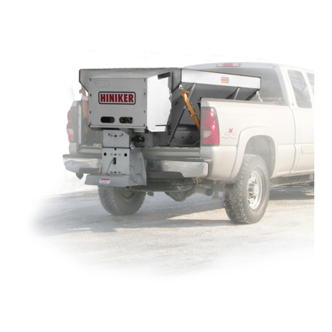
Hiniker 600P User manual

POLY RECEIVER HITCH SPREADER
MODEL: 600P & 1000P
OPERATOR’S MANUAL
DO NOT USE OR OPERATE THIS EQUIPMENT UNTIL THIS MANUAL
HAS BEEN READ AND THOROUGHLY UNDERSTOOD
Please visit www.snowplows.hiniker.com to access the most recent version
PART NUMBER 25014940


TABLE OF CONTENTS
TO THE PURCHASER.................................................................................................................. 2
SAFETY...................................................................................................................................... 3-4
OPERATING PROCEDURES .................................................................................................... 5-9
General Information................................................................................................................ 5
Sander Control Box................................................................................................................ 5
Spread Control ....................................................................................................................... 7
Transporting Spreader ........................................................................................................... 7
Spreader Optional Equipment................................................................................................ 7
Swing Away Kit....................................................................................................................... 8
Vibrator Kit.............................................................................................................................. 8
Storage................................................................................................................................... 9
MAINTENANCE & SERVICE PROCEDURES............................................................................ 10
TROUBLE SHOOTING ................................................................................................................11
INSTALLATION INSTRUCTIONS .......................................................................................... 12-14
SPECIFICATIONS....................................................................................................................... 15
WARRANTY ................................................................................................................................ 17
Table of Contents 1
25014940 10/23 Hiniker/25014940

TO THE PURCHASER
2 To The Purchaser
This product is designed and manufactured to
give years of dependable service, when properly
maintained and used for the purpose for which
it is intended. Never allow anyone to operate
this equipment until they fully understand the
complete contents of this manual. It is the
responsibility of owners who do not operate this
equipment to ensure the operator is properly
instructed and understands the contents of this
manual. It is also the owner’s responsibility to
ensure that anyone operating this equipment is
mentally and physically capable of so doing.
Important information is contained in this manual
to help ensure safe and efficient operation.
If you have any questions about this manual, or
the equipment discussed herein, contact your
Hiniker dealer.
This is a safety alert symbol. It alerts
an operator to information concerning
personal safety. Always observe and
heed these instructions, otherwise death, or
serious injury can result!
All references to LEFT or RIGHT mean viewing
the spreader from the rear and facing the truck.
This Operator’s manual is shipped with this
equipment. Contact your Hiniker dealer for
additional copies.
Always obtain original Hiniker service parts.
Substitute parts could adversely affect
equipment performance and warranty.
Check that your dealer has forwarded the
Hiniker delivery report copy and the machine
serial number to maintain maximum service
and warranty benefits. This does not put you on
any mailing list and information thereon is not
available to others.
Your spreader’s identification number plate is at
the location shown below.
Record the following information for later
reference when obtaining service parts:
Purchase Date
Purchaser’s Name
Dealer’s Name
Machine Serial No.

This is a safety alert symbol. It alerts
an operator to information concerning
personal safety. Always observe and
heed these instructions, otherwise death or
serious injury can result!
Operator safety is a principle concern in
equipment design and distribution. However,
many accidents occur because a few seconds
of thought, and a more careful approach to
handling, were ignored.
Accidents can be avoided by knowing and
following the precautions cited in this manual.
GENERAL SAFETY
1. Read this manual thoroughly. Make sure
the operator understands it and knows
how to operate this equipment safely.
This equipment can injure an untrained or
careless operator and bystanders. If you
sell this equipment, ensure the new owner
acknowledges receipt of this manual.
2. Make sure all safety guards are securely
mounted in place before operating this
spreader.
3. Do not attempt to handle or service this
equipment, or direct others to do the same,
unless you know how to do it safely and
have the proper tools for the job.
4. Keep hands, feet, hair, and clothing away
from moving/rotating parts. Flying material
can cause bodily injury. Wear eye protection.
5. Do not alter the equipment to the extent of
compromising safety or performance.
6. Material to be spread can be dangerous.
Improper selection, application, use or
handling may be a hazard to persons,
vehicle or other property. Follow instructions
and precautions given by the material
manufacturer.
SAFETY
7. Do not over-load your vehicle beyond
payload limits. If there are any questions,
contact the vehicle manufacturer.
8. Make sure spreader is securely fastened to
vehicle in accordance with this manual.
9. Do not operate a spreader in need of
maintenance or repair.
BEFORE OPERATION
1. Discipline yourself to visually check for
worn, damaged or cracked parts before
starting use. Replace these with genuine
Hiniker parts.
2. Check all controls and operating functions
of machine in a safe area before starting to
work.
3. Do not adjust or clean machine while it
is running. After making adjustments,
check machine thoroughly for loose parts,
hardware and tools.
4. Always disconnect wiring harness before
removing or replacing any electrical
components.
5. Verify hardware attaching safety cable to
cover and hopper is tight.
6. Make sure cover rubber latches are securely
fastened before driving motor vehicle.
Safety 3

4 Safety
DURING OPERATION
1. Drive carefully and always wear seat belts
when operating a motor vehicle. Braking
distance may be increased and handling
characteristics impaired due to extra weight
of spreader.
2. Ensure everyone is clear of machine,
especially away from blind areas of the
operator, before starting or operating this
equipment.
3. Stay out of hopper when auger power
source is engaged. If machine becomes
plugged or material bridges, do not attempt
to remove blockage until machine has been
shut o and auger and spinner movement
have stopped.
Use a shovel or other long-handled tool to
reach inside hopper. Never attempt to break
up material inside hopper with hands or feet.
4. Set brakes and stop truck’s engine before
adjusting or servicing your spreader.
AFTER OPERATION
1. Inspect spreader for components that have
become excessively worn or damaged and
must be repaired or replaced.
2. Develop a regular maintenance schedule
to ensure safe, dependable spreader
operation.
3. Never use swing away hopper feature with
material in spreader.
4. Never remove spreader with material in
hopper.
5. Disconnect power before servicing
equipment.
6. DO NOT leave unused material in hopper.
Material will freeze up or solidify causing
unit to malfunction. Empty and clean after
each use.

OPERATING PROCEDURES
GENERAL INFORMATION
Hiniker spreaders are capable of dispersing
a variety of dry materials for control of ice on
roadways, walkways and parking lots.
Vehicle load carrying capacity limits the
maximum load that can be safely transported,
which could be less than the volumetric capacity
of the spreader. Check the vehicle’s load rating
certication sticker and DO NOT overload
the vehicle beyond its Gross Vehicle Weight
Rating (GVWR) or its Gross Axle Weight Rating
(GAWR). Check carrying capacity of 2” receiving
hitch on vehicle. Be sure not to overload hitch.
Overloading could result in an accident or
damage to vehicle and spreader.
An alternator rated for 135 amps or higher is
recommended.
Use the following tables to calculate vehicle
payload when material is loaded in the spreader.
VOLUMETRIC CAPACITY:
(Cubic Feet, Approx.)
LEVEL
Hopper Capacity Model 600P 6
Hopper Capacity Model 1000P 10
WEIGHT: (Pounds, Approx.)
Hopper Assembly Model 600P 120
Hopper Assembly Model 1000P 136
MATERIAL WEIGHTS:
(Pounds Per Cubic Feet, Approx)
Rock Salt, Dry 80 - 90
Salt Sand Mix, Dry * 95 - 120
* A 1:1 ratio recommended for salt/sand mix to
prevent material from freezing.
Calculate total material weight by multiplying
pounds per cubic foot by cubic foot of material.
Always examine spreader for worn or damaged
components prior to operation. During operation,
listen for unusual noise from spreader that
might indicate component failure. Never run a
machine in need of repair.
Verify cover rubber latches are secure and
safety cable hardware is tight before operating
and driving of motor vehicle.
Start spreader for a short period of time before
loading material to test for proper function of
moving parts.
After loading, run spreader in an isolated area,
clear of people, to become familiar with controls
and to verify correct spread pattern.
Do not load material the night before or material
may take in moisture and solidify before
operation. Load material right before use to
avoid material solidifying.
If material bridges or solidifies remove all
material from hopper.
Do not leave unused material in hopper
overnight. Remove all material from hopper
after each day’s use.
SANDER CONTROL BOX
Hiniker controllers are equipped with variable
material feed, blast control, and a push button for
an optional vibrator. The variable speed knob is
clearly marked with full counterclockwise(CCW)
being minimum speed/power and full clockwise
(CW) being maximum speed/power.
Operating Procedures 5

6 Operating Procedures
To turn on controller, push and hold power
button until push button illuminates red in color.
The Hiniker controller will pulse the drive motor
on and off a few times then drive motor at full
power for a short duration to loosen material
in hopper. The motor will then go to operator’s
preset speed. The speed will be shown by which
numbers are illuminated red on the dial.
Example: If numbers up to 5 are red in color,
spreader is set for speed setting 5.
An optional vibrator is available which helps
keep a steady flow of material onto spinner. It
also slightly increases rate at which material is
applied because a vibrator helps to put maximum
amount of material onto conveying mechanism.
To activate vibrator, push vibrator button until
light beside “Vibrator” button is illuminated
green in color.
Important: Vibrator should be used only when
necessary. Excessive use of vibrator may
damage hopper. Vibrator is recommended to
only be used when hopper is about 1/2 to 1/3
full until empty. Vibrator is also necessary when
material is damp. Vibrator should be turned
on for short durations of time to help with
material flow but is not recommended to be ran
continuously at any time.
Blast feature is used for slippery spots that need
excess salt/sand. When blast button is held
down material feed drive system runs at full
power applying maximum amount of material.
Light beside “Blast” button will illuminate green
when blast feature is active. Once button is
released blast feature will stop, and normal
preset application will resume.
Hiniker has safety features built into the controller
to protect its electrical components and motors.
When a potentially damaging overload occurs
the controller variable speed knob will flash
red. The controller will then reduce the amount
of voltage allowed to the motor and pulse the
motor for 1 minute.
This is an attempt to loosen frozen, wet, or
clumping material. If the motor is still drawing
too many amps after 1 minute the controller will
then stop sending power to motor and controller
will continue to flash red.

Operating Procedures 7
When this happens the spreader is most likely
jammed with frozen, wet, or clumping material.
The operator will need to get out of truck to
investigate cause of jam.
Before checking hopper be sure controller is
turned off and vehicle is off and in park with
ignition key in operator’s pocket.
Hiniker spreaders are equipped with a bottom
hopper slide gate to make checking material
jams easier. This gate is also used to empty
material out of hopper after each days use or to
empty hopper if frozen, wet, or solidied material
is in hopper.
To open bottom slide gates rst loosen wing nut
on both slide gates. Pull on outer formed edge
of both gates simultaneously to open. Remove
blockage and then slide gates until they are
almost touching auger tube and retighten wing
nuts. Dry material may now be put into hopper.
Controller will need to be shut o and back on to
resume material spreading.
SPREAD CONTROL
Spread pattern is controlled by (2) variables
motor speed and vehicle speed. The drive and
spinner motor are coupled together making them
run at the same RPM. As the drive motor is sped
up the material feed rate is increased. This also
increases the speed of the spinner making a
wider less populated spread pattern. If the motor
is ran at a slower speed the feed rate decreases.
This will decrease the spinner speed and cause
a smaller but heavier populated spread pattern.
The other variable is vehicle speed, a slower
vehicle speed results in heavier populated
spread pattern.
TRANSPORTING SPREADER
When transporting Hiniker spreaders it is
essential that the spreader is tied down using
ratcheting tie down straps to the rear corners of
the spreader (as shown).
It is recommended to attach tie downs so they
are pulling at a frontward and upward angle.
This will help take some of the weight off the
receiver hitch as well as stabilizing the spreader.
It is recommended to attach the ratchet straps
to the tie downs in the bed of the truck.
WARNING: Verify cover is secure to
hopper before transporting vehicle or
death, injury, or vehicle damage could
occur.
It is important to verify cover is secured to
hopper using rubber latches before transporting
spreader or a potentially dangerous situation
may occur. Also verify safety cable hardware is
tight and cables are in good working condition.

8 Operating Procedures
SWING AWAY KIT (Optional)
Hiniker Swing Away Kit makes loading of pallets
of bagged material into the back of a vehicle
easier. The swing away option can only be used
when the hopper is completely empty.
For loading material into back of vehicle remove
pin. Lift up on rear of spreader hopper frame
while pulling out or away from vehicle to unhitch
hopper from swing away frame. Swing hopper
out of bed area to allow material to be loaded
into rear of vehicle.
To relock hopper in place, swing hopper until
prong touches receiver tube. Lift up on back
of spreader hopper frame and push prong into
receiver tube. Push hopper in until hitch pin can
be inserted locking hopper to receiver frame.
Insert hitch pin and secure with hairpin.
DWG NO. 7272
VIBRATOR KIT (Optional)
Hiniker vibrator kit is to eliminate bridging and
assure continuous ow of dry material to the
auger.
Important: Vibrator should be used only when
necessary. Excessive use of vibrator may
damage hopper. Vibrator is recommended to
only be used when hopper is about 1/2 to 1/3
full until empty. Vibrator is also necessary when
material is damp. Vibrator should be turned
on for short durations of time to help with
material flow but is not recommended to be ran
continuously at any time.

Operating Procedures 9
STORAGE
Store spreader in a cool dry protected area
when it will not be used for an extended period
of time. Never attempt to remove spreader with
material in hopper. Perform these maintenance
procedures at end of season to ensure machine
remains in good operating condition:
1. Unload hopper completely and wash to
ush out any remaining material to prevent
material buildup. Do not pressure wash
motor or electrical components or damage
will occur.
2. Disconnect and remove controller from
spreader. Store in a cool dry place. Summer
temperatures and climate could damage
circuit boards and void warranty.
3. Apply a light coat of dielectric grease to all
electrical terminals, and cap or tape loose
terminals to prevent damage or corrosion.
4. Inspect for worn or damaged components.
Repair or replace as needed.

10 Maintenance & Service Procedures
MAINTENANCE & SERVICE PROCEDURES
Dependable spreader operation is a result
of following good maintenance procedures.
Inspect your spreader frequently to ensure that
all parts are working smoothly, and develop a
schedule for maintenance at required intervals.
GENERAL
Always disconnect power from wiring harness
before servicing or replacing any electrical
components. Prior to operation of a new
spreader, or one that has been stored, inspect
all hardware and verify proper torque on all
bolts and nuts in accordance with recommended
torque specifications.
1 or 2 58
Manufacturer marks may very.
These are all SAE Grade 5 (3 - line).
DWG. NO. 1935
TABLE 1 RECOMMENDED TORQUE VALUES FOR INCH FASTENERS
(ZINC COATING & LUBRICATED)**
Nominal
Size
SAE 5
120,000 psi
Min Tensile Str
lbf - ft
SAE 8
150,000 psi
Min Tensile Str
lbf - ft
Dry Lubricated Dry Lubricated
1/4-20 8 6 12 9
5/16-18 17 13 25 18
3/8-16 30 23 45 35
1/2-13 75 55 110 80
5/8-11 150 110 220 170
** MACHINE DESIGN FASTENER AND JOINT REFERENCE ISSUE
Loose bolts can cause hole elongation and
part failure resulting in dangerous operating
conditions and equipment breakdown.
Check all hardware periodically during operation
and keep tightened to specified torques. Replace
worn bolts and locknuts, as needed.
Apply a light coat of dielectric grease to all
electrical connectors to prevent corrosion of
contacts when connectors are unplugged, and
to make connecting and disconnecting plugs
easier.
Remove all material from hopper and wash salt
and dirt off spreader before storage. Do not
pressure wash motor or electrical components
as damage may occur.
Never leave material in hopper overnight.
Material may freeze or solidify and seriously
damage spreader or components.
Controller is not serviceable. If controller does
not function a new one must be purchased.

Trouble Shooting 11
Preliminary Checks:
– Be sure all electrical connections are tight and clean.
– Be sure nothing is jammed in hopper or spinner.
TROUBLE SHOOTING
PROBLEM POSSIBLE CAUSE REMEDY
No power to cab
Power switched to ON position
No illumination of indicator light
Controller plug is loose
Blown fuse
Check plug connection at cab
control
Replace fuse
Faulty battery Check battery voltage should be
between 13 - 15 Volts with vehicle
running
Vehicle wiring harness damaged
between battery and controller
Repair/Replace damaged wires
or harness as required.
Control Dial does not change
speed
Controller does not function
Malfunctioning cab control Replace controller
Wiring harness is damaged or
has a short between cab control
and spreader
Check plug connections at cab
controller and spreader motors
Material feed motor does not
operate
Controller display blinks red
Material feed jam Remove obstruction
Frozen material
Solidied or clumping material
Thaw material
Replace material
Slide gates too tight on auger
shaft
Increase clearance between slide
gates and auger shaft
Material jammed between slide
gates and auger tube
Remove jammed material
Motor doesn’t run Loose electrical connections Check/tighten all connections
Jammed material feed/spinner Remove obstruction
Motor seized Replace motor
Material not owing from hopper Wet or Frozen material Replace with Dry material
Material feed jammed Remove obstruction
Material bridge Remove bridge

12 Installation Instructions
1 or 2 58
Manufacturer marks may very.
These are all SAE Grade 5 (3 - line).
DWG. NO. 1935
TABLE 1 RECOMMENDED TORQUE VALUES FOR INCH FASTENERS
(ZINC COATING & LUBRICATED)**
Nominal
Size
SAE 5
120,000 psi
Min Tensile Str
lbf - ft
SAE 8
150,000 psi
Min Tensile Str
lbf - ft
Dry Lubricated Dry Lubricated
1/4-20 8 6 12 9
5/16-18 17 13 25 18
3/8-16 30 23 45 35
1/2-13 75 55 110 80
5/8-11 150 110 220 170
** MACHINE DESIGN FASTENER AND JOINT REFERENCE ISSUE
MOUNTING SPREADER
1. Remove spreader from shipping container.
2. Remove zip tie securing grid to hopper.
Carefully remove grid from hopper to access
parts box.
3. Remove Hiniker controller, wiring harness,
ratchet straps, etc from parts box.
Verify everything has been removed from inside
the hopper.
INSTALLATION INSTRUCTIONS
4. Reassemble hopper grid and hopper cover
onto hopper assembly. Securely fasten
rubber latches.
5. Assemble 2” receiver assembly onto front
side of hopper assembly using provided
1/2” hardware, if not already assembled.
6. With hopper near 2” receiver on vehicle. Tip
spreader back and align bottom edge of 2”
spreader tube with vehicle 2” receiver. Slide
2” tube partially in and lift up while pushing
in to fully mount spreader in vehicle.
7. Secure spreader in place using provided
5/8” hitch pin and hairpin.

Installation Instructions 13
8. Use ratcheting tie down straps to secure
hopper to truck bed built in tie downs.
CONTROL BOX AND VEHICLE
WIRING INSTALLATION
Locate wiring harness removed from inside
hopper assembly.
To insure good performance of your spreader,
check condition of trucks electrical system.
Using a voltmeter, check alternator and battery
voltage. With engine running and headlights and
heater fan on, a good voltage reading should fall
between 13.0 and 15.3 volts. If reading falls out
of this range, check and adjust your electrical
system.
Refer to drawing 7295 on following page. Lay
out a wiring path for spreader wiring harness.
Connect wiring harness connectors to their
mating connectors on drive motor and vibrator
(if equipped). Drill all necessary holes or use
existing ones to pass connectors into truck cab.
Attach harness to truck frame. Do not route
wiring harness near exhaust system, or harness
may melt and short electrical system.
Mount controller in a convenient location in truck
cab. Do not mount controller directly in front of
heater vents, as this will raise temperature of
controller significantly and may cause damage
to your spreader controller.
CAUTION: Do not install controller in
deployment path of an air bag. Refer
to vehicle manufacturer’s manual for
air bag deployment areas.
Attach mating connectors between wiring
harness and cab controller.
CAUTION: Make sure power switch
on controller is off before connecting
power cable.
Lay out a path for power cable in truck’s engine
compartment. Drill a hole in firewall or use
an existing one to pass wiring harness. It is
recommended to pass power cable from inside
of cab to battery due to a large high amperage
connector. Do not route close to engine or
exhaust system, or harness may melt and short
electrical system.
Refer to drawing 7295 on following page.
Connect black lead to battery ground (-) terminal.
White is attached to positive (+) post of battery.
Connect power cable to controller.
Push on/off button on controller to check for
power. When power has been confirmed turn
power off. Electrical installation now is complete.
Refer to “Operating Procedures Section” for
more information on controller function.

DWG. NO. 7295
14 Installation Instructions

Specifications 15
SPECIFICATIONS
DIMENSIONS: 600P HOPPER 1000P HOPPER
Overall Length 25 Inches 29 1/2 Inches
Overall Width 32 Inches 38 1/4 Inches
Overall Height 36 1/2Inches 39 Inches
Hopper Length 24 Inches 28 Inches
Hopper Width 30 Inches 35 1/2 Inches
CAPACITY: Cubic Foot
Level 610
Weight: Model Hopper Only 120 lbs. 136 lbs.
AUGER:
Auger Diameter: 6 Inches 6 Inches
Electric Drive
Drive Motor 1/3 HP 12 V DC Electric Motor
Spinner Diameter: 10 Inches 10 Inches
Shaft Diameter: 3/4 Inch 3/4 Inch
Spreader Pattern Up To 25 Feet Up To 25 Feet

16 Notes
NOTES:

Hiniker Warranty 17
HINIKER SPREADER LIMITED WARRANTY
The only warranty Hiniker Company (Hiniker) gives and the only warranty that any Hiniker dealer is authorized to
give on behalf of Hiniker is as follows: (NO EMPLOYEE OR REPRESENTATIVE IS AUTHORIZED TO CHANGE
THIS WARRANTY IN ANY WAY OR GRANT ANY OTHER WARRANTY.)
Hiniker warrants to the original purchaser of a Hiniker spreader that Hiniker will repair or replace any defects
in material and workmanship that occur within two years from date of retail delivery except the following items:
Hiniker warrants that it will repair or replace any defects in materials or workmanship with respect to the paint
nish, any accessories, and service parts and components for a period of one year from date of retail delivery.
Hiniker’s obligation and liability under this warranty is expressly limited to repairing or replacing, at Hiniker’s
option, at an authorized Hiniker dealer location, the defective parts at no charge to the original purchaser.
HINIKER MAKES NO OTHER WARRANTY, EXPRESS OR IMPLIED AND MAKES NO WARRANTY OF
MERCHANTABILITY OR OF FITNESS FOR ANY PARTICULAR PURPOSE.
HINIKER’S OBLIGATION UNDER THIS WARRANTY SHALL NOT INCLUDE ANY TRANSPORTATION
CHARGES TO OR FROM THE AUTHORIZED HINIKER DEALER LOCATION OR ANY LIABILITY FOR
INCIDENTAL, INDIRECT OR CONSEQUENTIAL DAMAGE OR DAMAGES OF ANY KIND FOR LOST PROFITS
OR DELAY. If requested by Hiniker, products or parts for which a warranty claim is made are to be returned freight
prepaid to our factory. Any improper use, operation beyond rated capacity, substitution of parts not approved by
Hiniker Company, or any alteration or repair in such manner as in our judgment aects the product materially and
adversely shall void this warranty.
Hiniker reserves the right to make improvements or changes to any of it’s products without notice. Such
improvements or changes shall not trigger any obligation by Hiniker to update, modify or change any products
previously sold by Hiniker.
HINIKER does not warrant the following:
1. Used products.
2. Any product that has been repaired, modied or altered in a way not approved by Hiniker Company.
3. Depreciation or damage caused by normal wear, lack of reasonable and proper maintenance, failure
to follow Operators Manual Instructions, misuse, lack of proper protection during storage, or accident.
4. Parts replacement and service necessitated by normal wear or maintenance including, but not limited
to, auger ighting, electric motor, and spinner disc.
5. Paint nish damage caused by normal wear.
Hiniker does not assume any liability for any damage to a motor vehicle resulting from the attachment or use
of a Hiniker spreader. Compliance with applicable motor vehicle regulations is the responsibility of the installer.
Attachment of a Hiniker spreader to a motor vehicle is at the risk of the purchaser.
It is the responsibility of the original spreader purchaser to verify the original date of purchase.
Dealer must submit PRODUCT REGISTRATION and ll out a DELIVERY REPORT FORM online within 30 days
of retail delivery to initiate the warranty coverage.
HINIKER COMPANY
58766 240th Street
Mankato, MN 56001
PHONE 800-433-5620 -- FAX (507) 625-5883
https://snowplows.hiniker.com/
HINIKER WARRANTY
This manual suits for next models
1
Table of contents
Other Hiniker Spreader manuals
Popular Spreader manuals by other brands

Blizzard
Blizzard LP-10 owner's manual
PERFORMANCE ADVANTAGE COMPANY
PERFORMANCE ADVANTAGE COMPANY K5024 installation instructions

Phoenix
Phoenix SPC10e instruction manual
AGREX
AGREX XDI 1500 User and maintenance manual

Echo
Echo RB-100S Operator's manual
New Leader
New Leader L5034 G4 Assembly/operators/parts manual
