Hit-Hot HN-MFG-C User manual
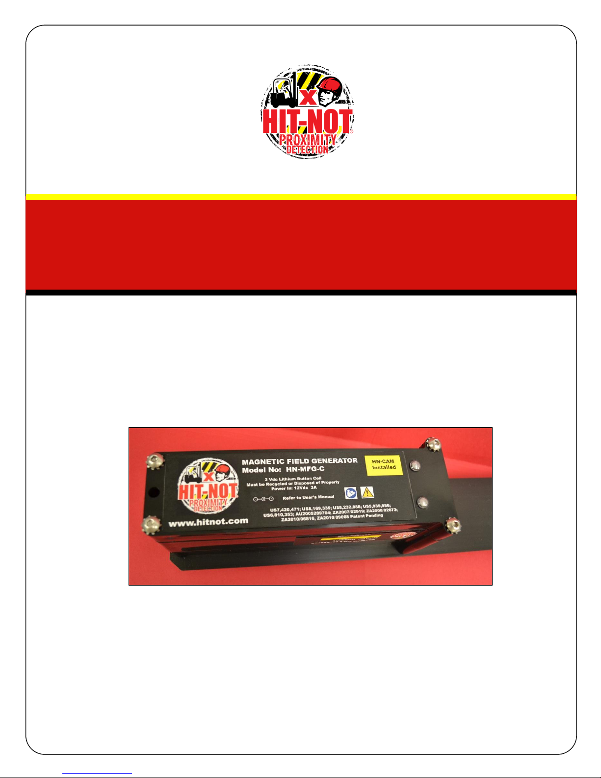
Exhibit 9
US7,420,471; US8,169,335; US8,232,888; US5,939,986;
US6,810,353; AU2005289704; ZA2007/02919; ZA2008/02673;
ZA2010/06816, ZA2010/09068 Patent Pending
Magnetic Field Generator
Including Collision Avoidance Module
User’s Manual v1.0
FREDERICK ENERGY PRODUCTS, LLC
1769 Jeff Road
Huntsville, AL 35806
1.800.489.6915
HIT-NOT Proximity System

Exhibit 9
US7,420,471; US8,169,335; US8,232,888; US5,939,986;
US6,810,353; AU2005289704; ZA2007/02919; ZA2008/02673;
ZA2010/06816, ZA2010/09068 Patent Pending
Table of Contents
1. Overview………………………………………………………………………………………………………….. 2-5
1.1 Theory of Operation……………………………………………………………………………… 2
1.2 Operating Frequency….………………………………………………………………………… 3
1.3 Label Information…………………………………………………………………………………. 3-4
1.4 FCC/IC Information……………………………………………………………………………….. 4-5
2. Operation…………………………………………………………………………………………………………. 6-11
2.1 Installation Information………………………………………………………………………… 6
2.1.1 Interoperability Warning…………………………………………………………………. 6
2.2 Charging……………………………………………………………………………………………….. 6
2.3 Alerts……………………………………………………………………………………………………. 6
2.4 Maintenance………………………………………………………………………………………… 6
2.5 Adjustments…………………………………………………………………………………………. 6-7
2.6 Interferences………………………………………………………………………………………… 7
2.7.1 Generator Specifications………………………………………………………………………. 7
2.7.2 CAM Specifications………………………………………………………………………………. 7-8
2.8 Installation Guides………………………………………………………………………….……. 8-11
2.9 Potential Safety Consideration…………………………………………………………….. 11
3. Warranty…………………………………………………………………………………………………………. 11-14
4. Revision History……………………………………………………………………………………………….. 15
1

Exhibit 9
US7,420,471; US8,169,335; US8,232,888; US5,939,986;
US6,810,353; AU2005289704; ZA2007/02919; ZA2008/02673;
ZA2010/06816, ZA2010/09068 Patent Pending
1Overview
The Magnetic Field Generator with CAM is part of a complete HIT-NOT Proximity Detection
system from Frederick Energy Products which provides warnings to both individuals and to
vehicle operators to alert them that the individual or vehicle has entered too close to an
operating piece of equipment and is in a dangerous situation. The Magnetic Field Generator
with CAM attaches directly to a vehicle or piece of machinery. The Collision Avoidance Module
(CAM) provides warnings to powered equipment when it is at risk of collision with another
truck. The operation of the CAM is similar to that of warnings for pedestrians, but a different
LED/Sounder pattern is used to denote a truck in a magnetic field zone than the one used for a
pedestrian in a zone.
1.1 Theory of Operation
The functions of the Magnetic Field Generator with Collision Avoidance Module are:
To generate a 73 kHz field around a vehicle or piece of machinery to act as a protection
zone for collision avoidance with equipment and for proximity detection for the
protection of individuals.
To receive a 916.48 MHz RF signal from a Personal Alarm Device (PAD) and/or a Collision
Avoidance Module (CAM).
To transmit a 916.48 MHz signal from the CAM to a Magnetic Field Generator in another
vehicle.
The Magnetic Field Generator with CAM (Vehicle 1) has an internal 73 kHz generator and an
inductor that creates a field to serve as a cautionary zone around the vehicle or machine. It
also contains a Collision Avoidance Module (CAM) with a 916.48 transmitter to notify the
Generator from another vehicle (Vehicle 2) of its close proximity. When Vehicle 1 is in close
proximity of Vehicle 2, the CAM (Vehicle 1) will detect the 73 kHz magnetic field from the
generator (Vehicle 2) and analyze its field strength. If the 73 kHz field strength received by the
CAM (Vehicle 1) is above a certain threshold, indicating the distance between Vehicle 2 and
Vehicle 1 is close enough to signify a Warning condition, then the CAM will reply to the
Magnetic Field Generator in Vehicle 2 with a 916.48 MHz transmission. The Magnetic Field
Generator has its 916.48 MHz receiver on when it is transmitting the 73 kHz field and is
“listening” to receive any 916.48 MHz transmissions from a Personal Alarm Device (PAD) or
generator equipped with a CAM to indicate the individual or vehicle is too close and warrants a
warning or danger condition. If the Magnetic Field Generator receives indication that a
Warning or Danger condition exists, it will turn on the appropriate LED indicator and connected
Warning Module (sounder for the Magnetic Field Generator).
2
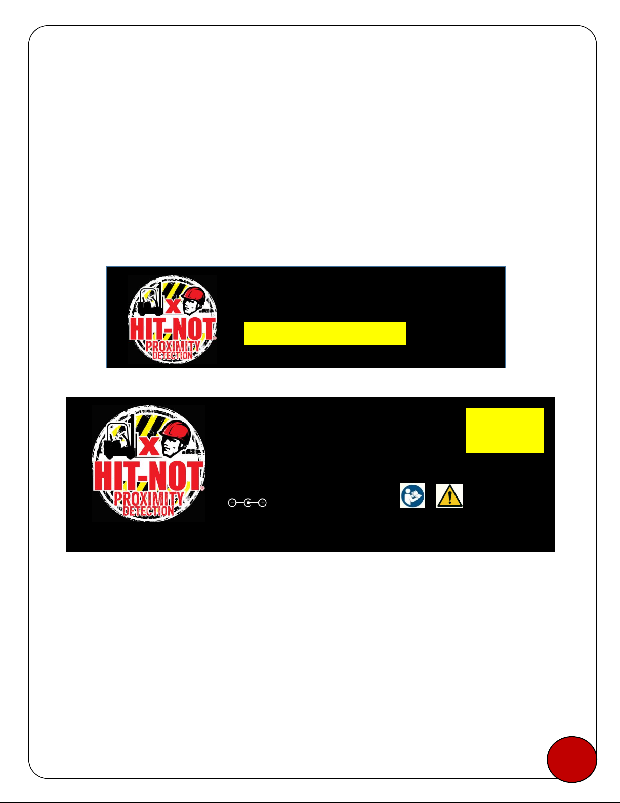
Exhibit 9
US7,420,471; US8,169,335; US8,232,888; US5,939,986;
US6,810,353; AU2005289704; ZA2007/02919; ZA2008/02673;
ZA2010/06816, ZA2010/09068 Patent Pending
1.2 Operating Frequency
The Magnetic Field Generator with CAM will transmit on a frequency of 73 kHz and receive on a
frequency of 916.48 MHz.The Collision Avoidance Module will transmit on a frequency of
916.48MHz and receive on a frequency of 73kHz. The CAM is programmed not to recognize the
73 kHz from its own Generator.
1.3 Label Information
The Magnetic Field Generator label is located on the top housing next to the LED lights to
indicate power and warning. Serial Number label is located on the side of the middle housing.
The CE label is on both the serial number label and the main label.
Proximity Module Labels
The HIT-NOT label defines the model and serial number of the Magnetic Field Generator. The
HN-CAM label is applied when the Collision Avoidance Module is integrated.
www.hitnot.com
MAGNETIC FIELD GENERATOR
Model No: HN-MFG-C
www.hitnot.com
m
US7,420,471; US8,169,335; US8,232,888; US5,939,986;
US6,810,353; AU2005289704; ZA2007/02919; ZA2008/02673;
ZA2010/06816, ZA2010/09068 Patent Pending
MAGNETIC FIELD GENERATOR
Serial No: MFG00200
3 Vdc Lithium Button Cell
Must be Recycled or Disposed of Properly
Power In: 12Vdc 3A
Refer to User’s Manual
3
HN-CAM
Installed
Exhibit 9
US7,420,471; US8,169,335; US8,232,888; US5,939,986;
US6,810,353; AU2005289704; ZA2007/02919; ZA2008/02673;
ZA2010/06816, ZA2010/09068 Patent Pending
FCC and IC Label for Proximity Module
1.4 FCC/IC Information
The FCC ID for the Personal Alarm Device is QUI-HN-MFG-C and complies with Part 15 of the
FCC Rules. Operation is subject to the following conditions:
1. This device may not cause harmful interference.
2. This device must accept any interference received including interference that may cause
undesired operation.
Any intentional or unintentional changes or modifications to the configuration of the Personal
Alarm Device not expressly approved by Frederick Energy Products LLC could void the user’s
authority to operate the equipment.
Note: This equipment has been tested and found to comply with the limits for a Class B digital
device, pursuant to Part 15 of the FCC Rules. These limits are designed to provide reasonable
protection against harmful interference in a residential installation. This equipment generates
uses and can radiate radio frequency energy and, if not installed and used in accordance with
the instructions, may cause harmful interference to radio communications. However, there is
not guarantee that interference will not occur in a particular installation. If this equipment does
cause harmful interference to radio or television reception, which can be determined by turning
the equipment off and on, the user is encouraged to try to correct the interference by one or
more of the following measures:
--Reorient or relocate the receiving antenna.
--Increase the separation between the equipment and receiver.
--Connect the equipment into an outlet on a circuit different from that to which the receiver is
connected.
--Consult the dealer or an experienced radio/technician for help.
Conformité aux normes FCC Cet équipement a été testé trouvé conforme aux limites pour un
dispositif numérique de classe B, conformément à la Partie 15 des règlements de la FCC. Ces
limites sont conçues pour fournir une protection raisonnable contre les interférences nuisibles
dans une installation résidentielle.
4
FCC ID: QUI-HN-MFG-C IC: 11625A-HNMFGWCA
Frederick Energy Products, LLC Model: HN-MFG-C Canada 310
This device complies with Part 15 of the FCC Rules. Operation is subject to the following two conditions: (1) This device may not cause harmful
interference, and (2) this device must accept any interference received, including interference that may cause undesired operation.

Exhibit 9
US7,420,471; US8,169,335; US8,232,888; US5,939,986;
US6,810,353; AU2005289704; ZA2007/02919; ZA2008/02673;
ZA2010/06816, ZA2010/09068 Patent Pending
Cet équipement génère, utilise et peut émettre des fréquences radio et, s'il n'est pas installé et
utilisé conformément ment aux instructions du fabricant, peut causer des interférences nuisibles
aux communications radio.
Rien ne garantit cependant que l’interférences ne se produira pas dans une installation
particulière. Si cet équipement provoque des interférences nuisibles à la réception radio ou de
télévision, qui peut être déterminé en comparant et en l'éteignant, l'utilisateur est encouragé à
essayer de corriger les interférence par une ou plusieurs des mesures suivantes:
--Réorienter ou déplacer l'antenne de réception.
--Augmenter la distance entre l'équipement et le récepteur.
--Branchez l'appareil dans une prise sur un circuit différent de celui auquel le récepteur est
connecté.
--Consulter le vendeur ou un technicien radio / expérimenté.
Les changements ou modififications à cet appareil sans expressément approuvée par la partie
responsable de conformité pourraient annuler l’autorité de l’utilisateur de faire fonctionner cet
équipement.
The required notices are specified in the RSS documents (including RSS-Gen) applicable to the
equipment model. These notices are required to be shown in a conspicuous location in the
user manual for the equipment, or to be displayed on the equipment model. If more than
one notice is required, the equipment model(s) to which each notice pertains should be
identified. Suppliers of radio apparatus shall provide notices and user information in both
English and French.
This device complies with Industry Canada license-exempt RSS-standards(s). Operation is
subject to the following two conditions:
(1) this device may not cause interference, and
(2) this device must accept any interference, including interference that may cause undesired
operation of the device.
Cet appareil est conforme avecx Industrie Canada exempt de licence Rss standard(s). Son
fonctionnement est soumis aux deux conditions suivantes:
(1) cet appareil ne peut causer d’interférence, et
(2) cet appareil doit accepter toute interférence, y compris des interférences qui peuvent
provoquer un fonctionnement indésirable du périphérique.
5

Exhibit 9
US7,420,471; US8,169,335; US8,232,888; US5,939,986;
US6,810,353; AU2005289704; ZA2007/02919; ZA2008/02673;
ZA2010/06816, ZA2010/09068 Patent Pending
2Operation
2.1 Installation Information
The Magnetic Field Generator with CAM is mounted on a vehicle or piece of machinery. The
Collision Avoidance Module is connected to the Generator via an interface header. Metal near
the Magnetic Field Generator may impact performance by reducing the field size. The CAM can
be blinded by a Xenon strobe light or a cab silencer if installed within 21 inches of the CAM.
After installing the Magnetic Field Generator/CAM on the machine, performance of the unit
should be verified by operation and test.
2.1.1 Inoperability Warning
The Magnetic Field Generator with CAM may experience erratic responses when in very close
proximity to some electronic devices. Electrical devices may transmit an electrical field and
noise from these fields may cause interference with the Magnetic Field Generator. A safe
guideline is to keep the Magnetic Field Generator at least 4in or 100mm away from any
electrical devices included but not limited to methane monitor, radio, mobile phone, GPS, PDA,
battery charger and laptop computers.
2.2 Charging
The Magnetic Field Generator/CAM is directly powered downstream when the ignition of the
vehicle is turned on and requires no charging.
2.3 Alerts
Magnetic Field Generators are designed to automatically adjust and maintain the original zone
size. If the truck supply voltage changes or changes occur resulting in a reduction of zone sizes,
the system will automatically adjust as much as 5% to ensure that the zones remain where they
were initially set. If the processor senses a significant power reduction, the alarm may sound for
a period of time. When the sounder is activated, power must be cycled to restore normal
operation. If the problem persists, then service is required.
The generator tolerates voltage fluctuations from 10-16V. A converter is needed for voltages
greater than 15V. If the processer switch (SW) on the PCB is in the OFF position, a continuous
alarm will sound at maximum dB.
2.4 Maintenance
The Magnetic Field Generator/CAM should be regularly cleaned to reduce buildup of dust and
dirt. The user should check to see if the LEDs are working before using the device.
2.5 Adjustments
Magnetic field size and Warning Module Volume are adjustments which are made on the
Magnetic Field Generator. To make the adjustments, remove the lid on the top housing. To
6
5

Exhibit 9
US7,420,471; US8,169,335; US8,232,888; US5,939,986;
US6,810,353; AU2005289704; ZA2007/02919; ZA2008/02673;
ZA2010/06816, ZA2010/09068 Patent Pending
adjust the magnetic field size, turn the screw located on the PWM pot. The volume to the
Warning Module can be adjusted by turning the screw on the VOL pot. Turning in a clockwise
direction will increase while turning counterclockwise will decrease the field or volume. If a
CAM is installed and adjustments need to be made on the generator, the CAM must be
disconnected to make the adjustments and then replaced. Adjustments must be made by a
professional.
2.6 Interferences
The Magnetic Field Generator may receive false triggering (generate an alarm) signals from
some RF-based devices including high power radios and cell phones. Such devices will need to
be moved further away from the generator. If the devices may not be moved, then the path
may need to be marked to indicate areas of interference of the system. If possible the route
may need to be changed. It may be possible for the generators to cause interference though
this should be rare because the average energy generated by this device is quite low at 73 kHz.
2.7.1 Generator Specifications
Part Number: HN-MFG
Size: 30” x 3.11” x 4.375” with Mounting Arm; 8.875” x 3.06” x 3.52” without Mounting Arm
Weight: 3.8 lbs./ 1.724 kg
Input Voltage: 12 VDC
Magnetic Field Frequency: 73 kHz pulsing AC field. Magnetic field pulses occur approx. 3% of the time.
Magnetic Field Strength: negligible
Maximum Current Draw: Less than 5A. It is not a constant draw with a magnetic field pulsing at 3% of
the time. Current draw between pulses is very low and the overall current draw is low.
Receiver Frequency: 916.48 MHz
Transmitter Frequency: 73 kHz
Operating Temperature Range: -30°C to + 55°C; -22°F to 131°F
Shipping Considerations: Contains a Lithium Metal Button Cell (packed in equipment)
2.7.2 CAM Specifications
Part Number: HN-CAM
Size: 3.81” x 2.92” / 97mm x 74.2mm
Weight: 4.7oz./ 133g
Input Voltage: 3.7 VDC
7
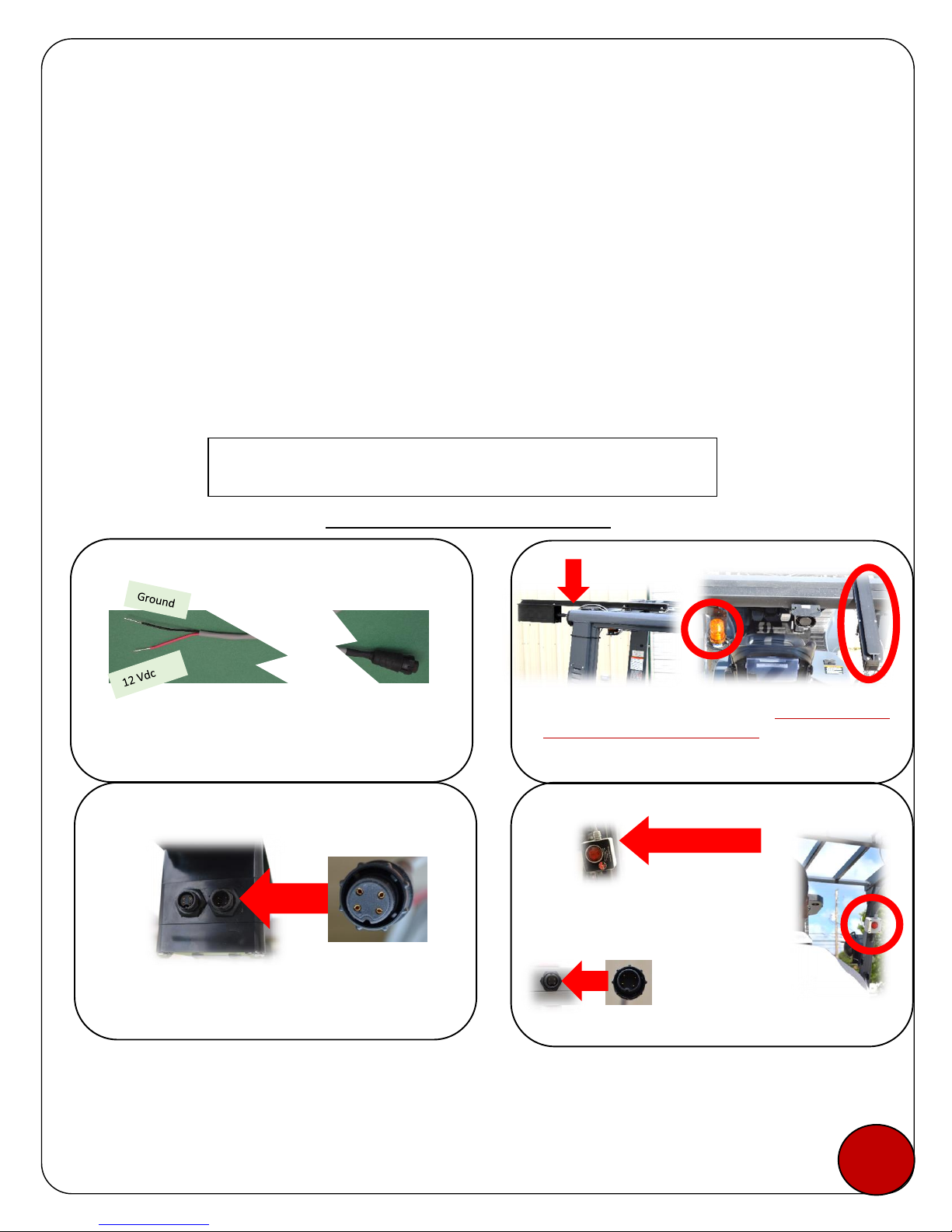
Exhibit 9
US7,420,471; US8,169,335; US8,232,888; US5,939,986;
US6,810,353; AU2005289704; ZA2007/02919; ZA2008/02673;
ZA2010/06816, ZA2010/09068 Patent Pending
Magnetic Field Frequency: none
Receiver Frequency: 73 kHz signal
Transmitter Frequency: 916.48 MHz
Transmitter Power: 0.001W (typical)
Operating Temperature Range: -20°C to + 50°C ; -4°F to 122°F
Environmental Considerations: 85 dBa nominal at 14 in. (35.6cm)
2.8 Generator System Installation Guide (Factory Installed CAM)
To Be Installed By a Professional
Step 1
Power Cable
Connect to a switched and fused (5A)
circuit.
Step 2
Install Generator
Install the Generator on top of the overhead guard and
at least 4”(10.2cm) from the frame. It should be as far
from the strobe light as possible. Adjust magnets to fit
the overhead guard. Use the U-Bolts to secure the
Generator to the overhead guard.
4 in.
Step 3
Power to Generator
Power Cable
Connect Power Cable (female) to Generator (male).
Turn locking ring to secure the connection.
Step 4
Install Warning Module
This connection pointed up
The CAM can be 1) Factory Installed when ordered, or 2) Retrofitted.
Retrofits are noted at the end of the Installation Guide (2.8.1).
Place magnet side of the Warning Module
to the frame of the forklift where it can be
seen and heard by the operator. Use of the
clear plastic cover is a company decision.
8
A second Warning Module can
be connected into the bottom
of the first Warning Module.
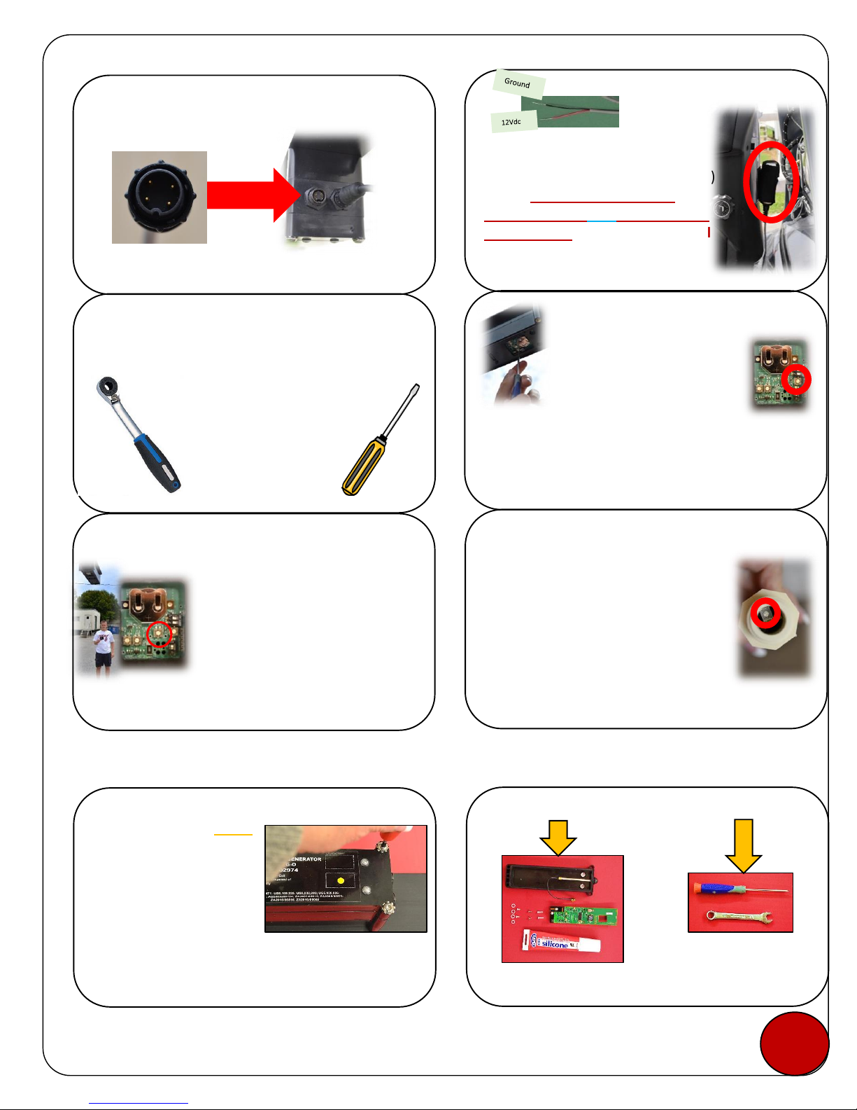
Exhibit 9
US7,420,471; US8,169,335; US8,232,888; US5,939,986;
US6,810,353; AU2005289704; ZA2007/02919; ZA2008/02673;
ZA2010/06816, ZA2010/09068 Patent Pending
2.8.1 Retro-fitted CAM Installation (By Qualified Dealer only)
*With a 5/32” hex driver, unscrew the bolts from
the label side of the generator. Keep the bolts
and lock washers to use on the new cover.
Step 5
Warning Module to Generator
Connect Warning Module (male) to Generator
(female).
Warning Module Cable
Step 8
Volume Adjust
•The clear plastic cover on the
Warning Module can be turned to
reduce the sound.
•Remove the bottom cover of the
generator with a 5/32”hex bit.
•Turn on the truck and activate the
PAD.
•Adjust the “VOL”pot with a 3/32”slotted screwdriver.
Increase volume-clockwise, decrease volume-
counterclockwise. Do NOT turn beyond the “STOP”.
•Return the bottom cover if Field Size is correct.
Step 10
Silent Zone Adjust
•Factory set to max. of ~22 in. or
56cm.
•To decrease the size, unscrew the cap
from the Cab Silencer.
•Activate a PAD and turn on truck.
•Using a 3/32”slotted screwdriver,
turn the Pot counterclockwise until
the PAD silences at the desired
location.
•Replace cap.
In order to avoid battery drain while
the vehicle is off, connect Cab
Silencer to a switched and fused (5A)
circuit. Place within 21”of the
Operator’s PAD AND 4ft away from
the generator. The Cab Silencer will
blind the CAM if installed on the
overhead guard.
Step 6
Cab Silencer
Step 7
Adjustments
All adjustments in Steps 8-10 need
to be done by a professional.
Step 9
Field Adjust
•Remove cover-see step 8
•Have a Pedestrian with a PAD at the
desired Danger Zone limit (~34’max.
or 10.3m), slowly adjust the “PWM”
pot (clockwise-increase field,
counterclockwise-decrease field with a
3/32”slotted screwdriver until the
danger zone alerts at the desired
distance.
•Return bottom cover.
Step 1
Remove Cover
*Make sure there is a yellow
dot to indicate the generator
is CAM ready. If there is no
sticker, the generator may
not be ready for a CAM.
Contact HIT-NOT.
Step 2
Installation Kit & Materials Needed
-8mm crescent wrench
-Small Phillips head screwdriver
are needed for installation
Items in CAM Kit
9
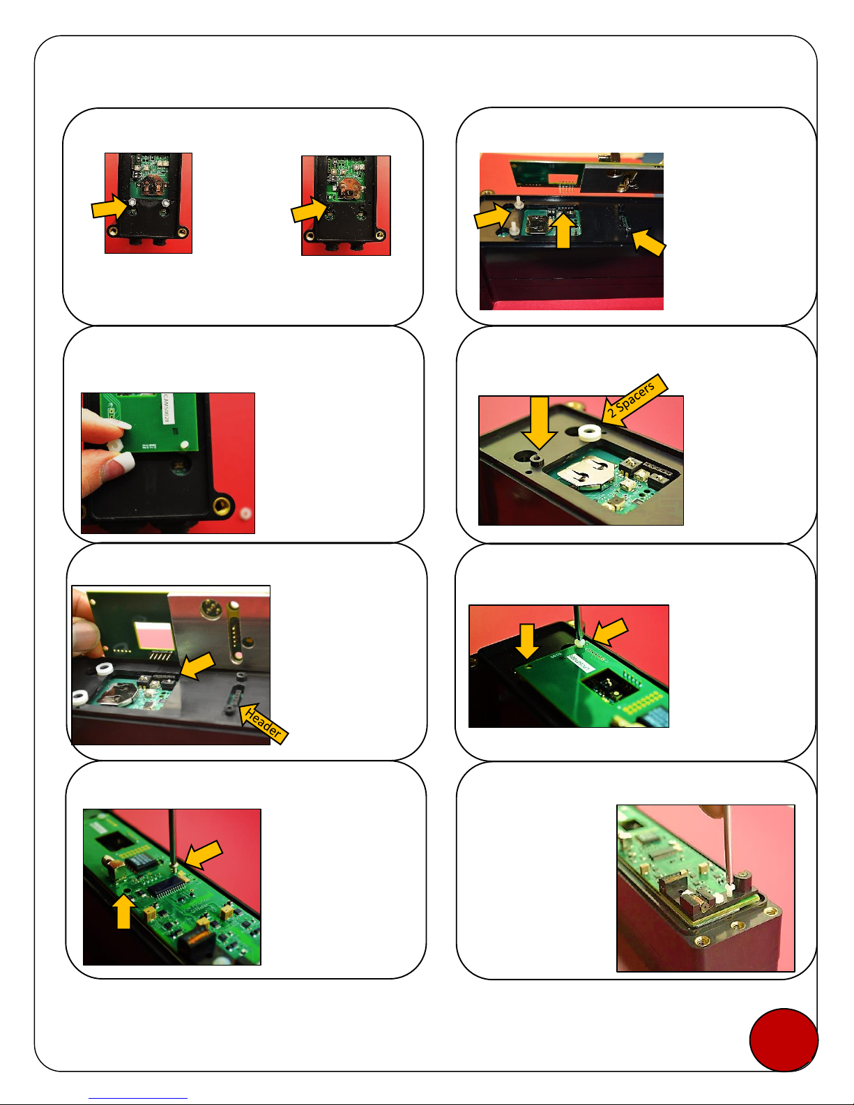
Exhibit 9
US7,420,471; US8,169,335; US8,232,888; US5,939,986;
US6,810,353; AU2005289704; ZA2007/02919; ZA2008/02673;
ZA2010/06816, ZA2010/09068 Patent Pending
Step 3
Step 4
Step 5
Step 6
Step 7
Step 8
Step 9
Spacer Placement
Stack 2 spacers
and place them
over a boss
next to the
open end of the
generator.
Repeat for the
other boss.
Boss
Take the CAM
board, metal side
down, and line up
both sets of pins
over the headers.
Press the CAM
firmly so that the
pins go directly
into both headers.
CAM Placement
Securing the CAM
Use the 2
shorter plastic
screws to screw
the CAM board
to the housing
(thru the
spacers and into
the bosses).
Securing the CAM pt.2
Use the 2 metal
screws to secure
the middle part
of the CAM
board to the
housing.
Securing the CAM pt.3
Use the 2 longer
plastic screws to
connect the L-
bracket end of
the CAM board
to the housing.
Step 10
Determine CAM Configuration
Has 2 white plastic screws,
with plastic nuts, standing
up. GO TO STEP 4.
Has 2 black plastic
raised circles. GO
TO STEP 6.
CAM Placement
Securing the CAM
Place the 2 holes at
the end of the CAM
board over the 2
white plastic screws.
Align the pins in the
board with the
header and press
firmly into place.
Secure the CAM
into place by
screwing on the 2
plastic nuts on the
screws. Hand
tighten. GO TO
STEP 9.
10
0
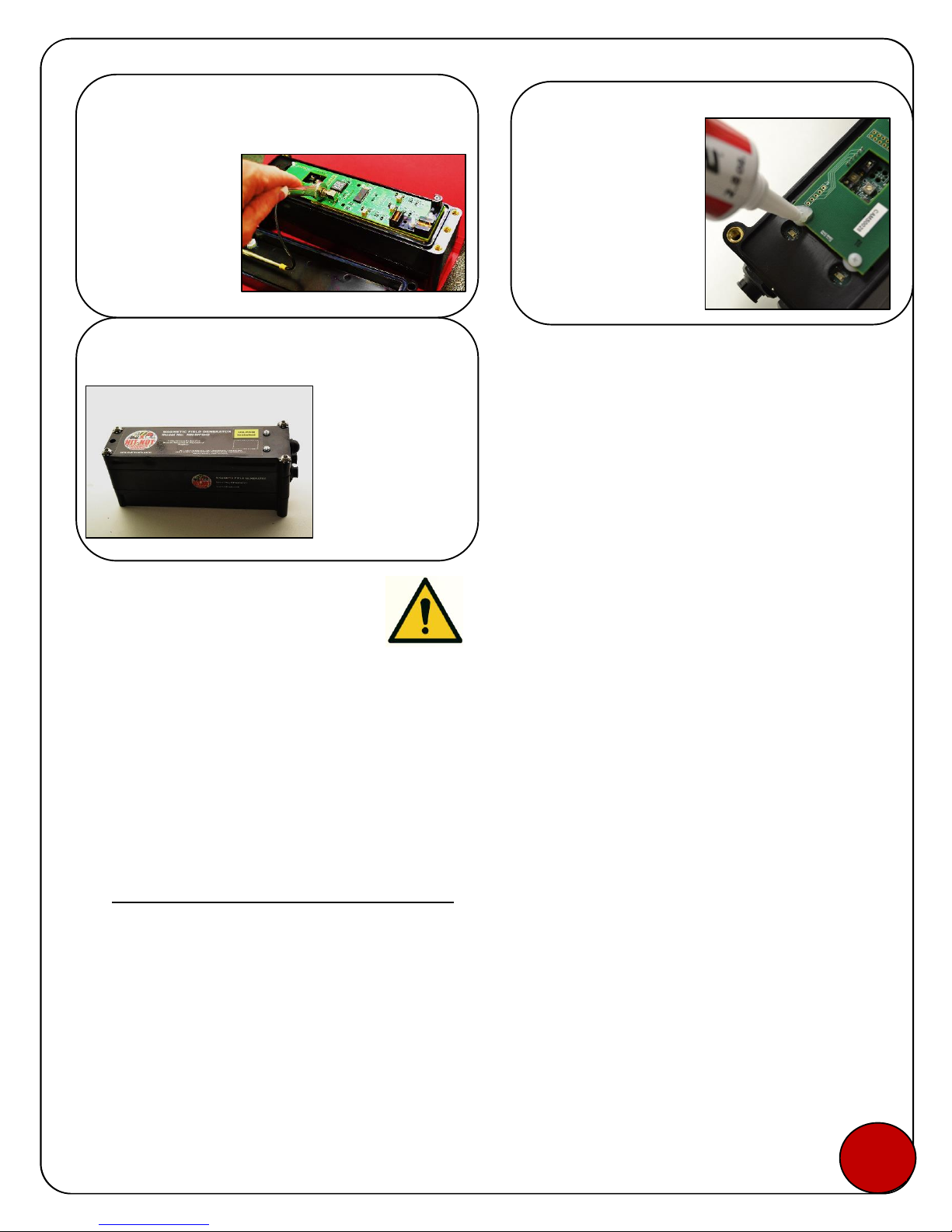
Exhibit 9
US7,420,471; US8,169,335; US8,232,888; US5,939,986;
US6,810,353; AU2005289704; ZA2007/02919; ZA2008/02673;
ZA2010/06816, ZA2010/09068 Patent Pending
2.9 Safety Consideration
The driver and pedestrian should not be in close proximity while the truck is in gear. The driver
must turn off the truck while a pedestrian is standing next to the truck. An alternate solution is
a switch applied to the emergency brake to cut the circuit to the generator while the brake is
activated.
3 Warranty
HIT-NOT® WARRANTY TERMS AND CONDITIONS
IMPORTANT-READ CAREFULLY: BY AND INSTALLING AND USING THE HIT-NOT® SYSTEM, YOU
ACKNOWLEDGE AND AGREE TO BE CONTRACTUALLY BOUND BY THESE WARRANTY TERMS AND
CONDITIONS. IF ANY OF THE TERMS OF USE ARE NOT ACCEPTABLE TO YOU, DO NOT INSTALL OR USE
THE HIT-NOT® SYSTEM. THE HIT-NOT® SYSTEM IS NOT GUARANTEED TO PREVENT ACCIDENTS.
THE HIT-NOT® SYSTEM IS SIMPLY A TOOL TO BE USED TO ASSIST YOU IN SAFELY OPERATING HEAVY
EQUIPMENT. THE HIT-NOT® SYSTEM IS NOT INTENDED AS A SUBSTITUTE FOR, NOR DOES IT REPLACE,
SAFE PRACTICES IN OPERATING HEAVY EQUIPMENT. YOUR USE OF THE HIT-NOT® SYSTEM IS SOLELY
AT YOUR OWN INDEPENDENT DISCRETION AND RISK.
Attach the Antenna
The top housing
(with label) contains
the antenna. Screw
the antenna into the
port on the CAM
board. Tighten with
an 8mm crescent
wrench.
Final Step
Install the new lid
with antenna on the
generator
housing/CAM
board. Reuse the 4
screws and lock
nuts with the 5/32”
hex wrench and
hand tighten.
Put Silicone #388 on
all 6 connection
points and make good
contact with the
board. This is
electronic grade
silicone. No
substitutes allowed!
Secure with Silicone
Step 11
Step 12
Step 13
11
00

Exhibit 9
US7,420,471; US8,169,335; US8,232,888; US5,939,986;
US6,810,353; AU2005289704; ZA2007/02919; ZA2008/02673;
ZA2010/06816, ZA2010/09068 Patent Pending
ACCEPTANCE AND DEFINITIONS.
(A) Acceptance of Terms. These Warranty Terms and Conditions (these “Terms”) are a legal
agreement between You, as a purchaser and end user of the System and Frederick Energy Products, LLC.
By installing the System or using the System in any way, You are (1) agreeing to be bound by these
Terms. If You do not agree with all these terms, do not use OR INSTALL the SYSTEM. YOU MUST
RETURN THE SYSTEM TO THE DEALER FROM WHICH YOU PURCHASED THE SYSTEM, IN ACCORDANCE
WITH THE DEALER’S POLICIES. This Agreement constitutes the entire and only agreement between FEP
and You and supersedes all prior or contemporaneous agreements, representations, warranties and
understandings with respect to the System, and the subject matter of this Agreement.
(B) Definitions. In this Agreement, “You” and “Your” refer to You as the user of the System. “FEP”
“we,” “us” and “our” refer to Frederick Energy Products, LLC and our successors, partners, affiliates,
subsidiaries and assigns. “System” refers to the Hit-Not®System purchased by You. “Terms” refers,
collectively, to these Warranty Terms and Conditions.
LIMITED WARRANTIES; DISCLAIMER.
(A) Limited Warranty. FEP hereby warrants against: (1) defects in the System, either in
workmanship or material, and (2) the failure of the System to conform to FEP’s written specifications,
for a period of one (1) year after date of delivery to You, in each case; provided that such System has
been under proper and normal use at all times during such period. All warranty claims under these
Terms must be submitted through the Dealer from which you purchased the System. FEP’s liability is
restricted to the replacement or repair of the defective or nonconforming parts alone and does not
include any installation, labor, or expense involved, or other contingent liability. Liability for any
components manufactured by third parties but incorporated into FEP Products to be furnished by FEP,
shall be limited to the guarantee or liability to FEP of the manufacturer or supplier of such components.
FEP is not liable for damages resulting from the use or misuse of the FEP Products.
(B) Disclaimers. EXCEPT AS EXPRESSLY SET FORTH ABOVE: (1) NO ADVICE OR INFORMATION,
WHETHER ORAL OR WRITTEN, PROVIDED BY OR THROUGH FEP, ANY DEALER OR DISTRIBUTOR, OR
ANY THIRD PARTY SHALL IMPLY THE CREATION OF ANY REPRESENTATION OR WARRANTY OF ANY
KIND WHATSOEVER BY FEP; (2) THE SYSTEM IS PROVIDED "AS IS" AND WITHOUT ANY WARRANTY OF
ANY KIND, EITHER EXPRESS, STATUTORY OR IMPLIED, INCLUDING, BUT NOT LIMITED TO, THE IMPLIED
WARRANTIES OF MERCHANTABILITY AND FITNESS FOR A PARTICULAR PURPOSE; (3) FEP DOES NOT
REPRESENT OR WARRANT THAT THE SYSTEM WILL BE FUNCTIONAL OR DEFECT-FREE, OR THAT
DEFECTS WILL BE CORRECTED; AND (4) FEP HEREBY DISCLAIMS ANY AND ALL LIABILITY OR
RESPONSIBILITY FOR THE IMPROPER USE OF THE SYSTEM OR FOR THE INCORRECT OR IMPROPER
INSTALLATION OF THE SYSTEM. SOME STATES OR OTHER JURISDICTIONS DO NOT ALLOW THE
EXCLUSION OF IMPLIED WARRANTIES, SO THE ABOVE EXCLUSIONS MAY NOT APPLY TO YOU. UNDER
NO CIRCUMSTANCES WILL FEP BE LIABLE FOR ANY LOSS OR DAMAGE CAUSED BY YOUR USE OF THE
SYSTEM. USE OF THE SYSTEM IS AT YOUR SOLE RISK.
INDEMNIFICATION; RELEASE; LIMITATION OF LIABILITY.
12
12

Exhibit 9
US7,420,471; US8,169,335; US8,232,888; US5,939,986;
US6,810,353; AU2005289704; ZA2007/02919; ZA2008/02673;
ZA2010/06816, ZA2010/09068 Patent Pending
(A) Indemnification. You agree to indemnify and hold FEP, any and all parent, subsidiary, and affiliate
organizations, and their respective officers, directors, agents, shareholders, members, managers,
advisors, consultants, employees, successors and assigns (collectively, the “Protected Parties”) harmless
from and against all losses, costs, liabilities, expenses (including reasonable attorneys’ fees and
expenses), claims, demands, and damages, actual and consequential, of every kind and nature, known
and unknown, suspected and unsuspected, disclosed and undisclosed (collectively, “Losses”), that are in
any way due to or arising out of Your use of the System, unless caused by the gross negligence or willful
misconduct of FEP. FEP reserves the right, at Your expense, to assume the exclusive defense and control
of any matter for which You are required to indemnify any of the Protected Parties, and You agree to
cooperate with FEP’s defense of such claims. FEP will use reasonable efforts to notify You of any such
claim, action, or proceeding which is subject to this indemnification upon FEP becoming aware of it.
(B) Limitation of Liabilities. IN NO EVENT SHALL FEP, ITS LICENSORS, SUPPLIERS, CONTENT PROVIDERS
OR THEIR RESPECTIVE PARENTS, SUBSIDIARIES, AFFILIATES, OFFICERS, DIRECTORS, SHAREHOLDERS,
ADVISORS, CONSULTANTS, EMPLOYEES, SUCCESSORS OR ASSIGNS, BE LIABLE TO YOU OR ANY THIRD
PARTY FOR ANY INDIRECT, SPECIAL, INCIDENTAL, CONSEQUENTIAL, PUNITIVE OR EXEMPLARY DAMAGES
(INCLUDING BUT NOT LIMITED TO LOSS OF BUSINESS, PROFITS, USE, REVENUE OR OTHER ECONOMIC
ADVANTAGE), ARISING OUT OF OR IN CONNECTION WITH THE SYSTEM OR THESE TERMS BASED ON ANY
THEORY, EVEN IF ADVISED OF THE POSSIBILITY OF SUCH DAMAGES. THE LIMITATION OF DAMAGES SET
FORTH ABOVE IS A FUNDAMENTAL ELEMENT OF THE BASIS OF THE BARGAIN BETWEEN US AND YOU.
THE SYSTEM WOULD NOT BE PROVIDED FOR SALE TO YOU WITHOUT SUCH LIMITATIONS. IN NO EVENT
WILL OUR LIABILITY, OR THE LIABILITY OF OUR LICENSORS, AND OUR RESPECTIVE PARENTS, AFFILIATES,
SUBSIDIARIES, OFFICERS, DIRECTORS, SHAREHOLDERS, EMPLOYEES, ADVISORS, CONSULTANTS,
SUCCESSORS OR ASSIGNS, TO YOU OR ANY THIRD PARTIES IN ANY CIRCUMSTANCE EXCEED ONE
HUNDRED DOLLARS (US $100.00). SOME STATES OR OTHER JURISDICTIONS DO NOT ALLOW THE
EXCLUSION OR LIMITATION OF INCIDENTAL OR CONSEQUENTIAL DAMAGES, SO THE ABOVE
LIMITATIONS AND EXCLUSIONS MAY NOT APPLY TO YOU.
Choice of Law; Dispute Resolution. The Agreement shall be governed by, and construed in accordance
with the laws of the State of Alabama, without regard to its conflicts of law provisions. In the event of
any dispute, claim, question or disagreement (“Claim”) between You and FEP arising from or relating to
Your use of the System, You and FEP will attempt, in good faith, to resolve any Claim within thirty (30)
days after written notice of the Claim. Any Claim not so resolved shall be finally settled by binding
arbitration administered by the American Arbitration Association under its Commercial Arbitration
Rules, using the Expedited Procedures. Judgment on the award rendered by the arbitrator(s) may be
entered in any court of competent jurisdiction. The arbitrator shall be an individual generally skilled in
the legal and business aspects of the subject matter of this Agreement. The arbitrator shall have no
authority to impose penalties or award punitive damages. The arbitration shall take place in Madison
County, Alabama, and the arbitrator shall apply the law of the State of Alabama and applicable rules of
evidence. If all parties and the arbitrator agree, arbitration may take place by telephone or by written
communication. Unless the arbitrator otherwise directs, the parties, their representatives, other
participants, and the arbitrator shall hold the existence, content, and result of the arbitration in
confidence. No action, regardless of form, related to the obligations of the parties under this Agreement
may be brought by either party against the other more than one (1) year after the cause of action has
accrued. In any proceeding to enforce this Agreement, the prevailing party will have the right, in
13
12

Exhibit 9
US7,420,471; US8,169,335; US8,232,888; US5,939,986;
US6,810,353; AU2005289704; ZA2007/02919; ZA2008/02673;
ZA2010/06816, ZA2010/09068 Patent Pending
addition to its other rights hereunder, to recover its reasonable litigation costs and reasonable
attorneys’ fees.
Nothing in this Section shall preclude any party from seeking equitable relief from a court of competent
jurisdiction or exercising any self-help remedies, whether before, during or after the pendency of any
arbitration proceeding. The parties agree that taking any such action does not waive any right that
either party has to demand arbitration at any time with respect to subsequent or amended disputes
claimed or filed against a party after commencement of litigation. BY AGREEING TO THESE TERMS AND
CONDITIONS, ALL PARTIES AGREE TO WAIVE ANY RIGHTS TO A JURY OR COURT TRIAL. If any provision
of this dispute resolution procedure is held invalid or unenforceable, the remaining provisions shall
remain in full force and shall not be affected by the invalidity of any other provision.
By tapping "Accept", you again agree and confirm that you have read and understood these Terms of
Service and the Disclaimer.
Accept
V. Entire Agreement; Assignment; Miscellaneous. These Terms constitute the complete and
exclusive statement of the agreement between You and us. It supersedes any and all prior or
contemporaneous agreement, oral or written, and any other communications, representations,
warranties and understanding relating to the subject matter hereof. If there is a conflict between an oral
or written representation of any FEP employee or agent, or any Dealer or Distributor employee or agent,
and these Terms, these Terms will prevail. These Terms will prevail over other rules and policies on the
System. Our failure to enforce any provision of these terms shall not be deemed either a waiver of such
provision or a waiver of the right to enforce such provision. If any provision of these Terms is held by an
arbitrator or court of competent jurisdiction to be contrary to law, then such provision shall be
construed, as nearly as possible, to reflect the intentions of the parties and the other provisions shall
remain in full force and effect. The provision of these Terms which, by their terms should survive
termination or expiration of these Terms, shall survive the termination or expiration hereof. FEP may
assign this Agreement to any other entity of its choosing, with or without notice to You. You may not
assign these Terms to any other party without the prior written consent of FEP. FEP shall not be deemed
to have waived any of its rights or remedies unless such waiver is in writing and signed by FEP. No delay
or omission on the part of FEP in exercising any rights or remedies shall operate as a waiver of such
rights or remedies or any other rights or remedies on future occasions. The section titles in these Terms
are solely used for the convenience of the parties and have no legal or contractual significance.
END OF HIT-NOT® WARRANTY TERMS AND CONDITIONS
14
12

Exhibit 9
US7,420,471; US8,169,335; US8,232,888; US5,939,986;
US6,810,353; AU2005289704; ZA2007/02919; ZA2008/02673;
ZA2010/06816, ZA2010/09068 Patent Pending
4 Revision History
4.1 Version 1.0 –October 4, 2013
Original Release. No revision history.
4.2 Version 2.0 –January 21, 2014
CAM Installation information included.
4.3 Version 3.0 –April 10, 2014
Health information updated
Section 2.10 added
4.4 Version 3.1 –April 10, 2014
Section 2.9 Removed
Section 2.10 reassigned as 2.9
4.5 Version 4.0 –November 26, 2014
Section 1.1 Theory of Operation amended
Section 1.3 Pictures changed
Addition in Warranty
15
0
Table of contents


