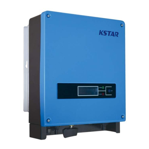
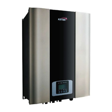
KStar KSG-3.2K-DM User manual

201702 Ver 1.2
Solar InverterSolar Inverter
User Manual
KSG-3.2K/3.6K/4K/4.6K/5K-DM

Installation and Operation Manual 1
Table of Contents
1 User Guide..........................................................................................2
2 Safety Instructions.............................................................................3
3 Product Warranty...............................................................................5
4 Overview...........................................................................................6
4.1 Introduction of Grid-connected Syste .........................................6
4.2 Brief Introduction of PV Inverter...................................................7
4.3 Features Description......................................................................8
5 Installation.........................................................................................9
5.1 Packing ..........................................................................................9
5.2 Installation of Inverter ...................................................................9
5.3 Installation Location....................................................................10
5.4 Installation Procedure..................................................................10
5.5 Wiring..........................................................................................12
5.6 Connection Procedure .................................................................14
6 Operation of Grid-connected Inverter.............................................15
6.1 Trial Operation.............................................................................16
6.2 Working Status ...........................................................................16
6.3 LED Display................................................................................18
6.4 LCD Display................................................................................19
6.5 Max Power Point Tracking (MPPT)............................................29
7 Co unication Interface................................................................30
7.1 RS232...........................................................................................30
7.2 RS485...............................................................................30
7.3 Dry Contact .................................................................................31
7.4 Re ote control ............................................................................31
8 Trouble Shooting.............................................................................32
9 Specification
.
.....................................................................................35
Installation and Operation Manual 2
1 User Guide
It is appreciating that you purchase single-phase grid-connected inverter
produced by our co pany. The product is non-transfor ing type
inverter, features reliable perfor ance and advanced technology. It
converts DC currents fro solar arrays into AC currents then fed to
unicipal Electrical Grid.
This anual contains i portant safety and operational instructions
that ust be accurately understood and followed before operating the
products.
Please refer to this anual once there is any proble during
installation or operation. Please contact your local distributors or
agent if not recovered by yourselves.
Thank you again for using our products, please read this anual
co pletely and hope you are satisfied with our products.
Please retain this anual for future reference.

Installation and Operation Manual 3
2 Safety Instructions
1. Electric Shock
The product has alternating current (AC) and direct current
(DC) connections, in order to avoid any electric shocks during
aintenance or before installation, please ake sure the
disconnection of these AC or DC ports, grounded for solar
syste and inverter.
2. Operation of Inverter
The product can be only operated or aintained by
professionals. The inverter can only be activated under such
situation: the housing or cover in good condition without any
da ages, all screws are tightened in right positions.
Before opening the inverters, it ust be disconnected with solar
array and Grid. In order to discharge co pletely fro storage
capacitance, you can’t touch the inverter within at least 5
inutes after disconnection.
. Requirement for Grid Connections
These inverters are only used for supply power for unicipal
power grid, and don’t try to connect any other energy resources
with this inverter.
4. High Temperature Protection
During nor al operation period, so e parts (such as cooling
fins and cover) is heating. So eti es it will reach 60 . Please ℃
don’t touch these parts to avoid scald.
Only qualified electricians are allowed to operate on
the inverter.
Only qualified electricians are allowed to install the
inverter.
Do not carry out any wiring and inspection or changing
co ponents when the power supply is applied. Hazardous
voltages ay still be present in the inverter even if the AC

Installation and Operation Manual 4
and DC ain switches are switched off. Wait at least 5
inutes after switching off the inverter. This ensures that
the capacitors are electrically discharged.
This product can cause a d c current in the external
protective earth conductor. Where a residual
current-operated protective (RCD) or onitoring (RCM)
device is strongly reco end to used for protection in a
case of direct or indirect contact, only an RCD or RCM of
Type B is allowed on the supply side of this product;
Must be grounded before operation.
Ensure the proper grounding of the inverter, otherwise, i proper
connection or no grounding ay cause stop of the inverter.
Ensure reliable installation and electrical connection.
When the photovoltaic generator cells are exposed to light (even
if it is di ), the generator supplies DC voltage to the inverter.
The reco ended solar odules need to co ply with IEC61730
Class A rating.
The grid-tied solar inverters are only for crystalline silicon solar
odules.
In order to protect the PCE, user and installer, external DC and
AC circuit breaker shall be equipped at the end-use application;
The wiring shall be according local electric code. Choose proper
cable for power input and output lines. Input and output cable
shall be PV private cables suitable for outdoor use.
Only qualified cables under the local electrical safety laws and
regulations are allowed to connect.

Installation and Operation Manual 5
Product Warranty
If you like to extend your warranty period, you can apply for it and
keep up warranty card well. The aintenance is free of charge during
warranty period. The packing aterial should be original or si ilar
aterial when the defective inverter is returned back to factory for
repairing.
This product is guaranteed to cover all shortage or da age due to
design, production, or co ponents. But the warranty doesn’t cover the
followings:
Beyond warranty period
No effective warranty card and product’s series nu ber
Da age caused i proper delivery
Da age caused i proper installation, unauthorized odification,
aintenance, or test, etc.
Da age caused by working in terrible environ ent which is not
co plied with stipulations in this anual
Da age caused not co ply with installation and operation range in
relative international standards or regulations
Da age caused by unnatural environ ent

Installation and Operation Manual 6
P
V
P
ane
l
PV I
n
v
e
r
t
e
r
AC
-
Connection
Unit
F
eeding
AC
pow
er to P
ubli
c
U
t
ili
ty
onl
y
-
+
DC
-
Input
AC-Output
G
r
i
d
(
Public Utility
)
4 Overview
4.1 Introduction of Grid-connected System
Basically Grid-connected syste is co prised of 4 portions: PV array,
PV inverter, AC connection unit and Public Grid connection unit.
Once PV arrays receive sun shines, they will generate DC current and
feed into PV inverter which is configured between DC input and
unicipal AC grid. Through converting DC into AC, the solar energy is
trans itted into unicipal Electrical Grid.

Installation and Operation Manual 7
4.2 Brief Introduction of PV Inverter
The inverter coverts DC current fro solar units into AC current,
and feeds to Municipal Electrical Grid. The inverter is designed and
produced as per relative require ent of laws and regulations. The
shape and functions of relative parts is described as follows:
1.LCD display panel: display working status and power efficiency etc
infor ation.
2.LED and button: 2 LED indicates current working status, 1 button is
used to switch current LCD display infor ation.
1.LCD display panel
2.LED & Button
3.DC input ports
4.DC-Switch
5.Waterproof air valve
6.AC output port
7.RS485
8.Dry Contact port
9.RS232 port

Installation and Operation Manual 8
3.DC input ports: Inverters have 2 pairs of DC ports, each pair of input
ports have positive (+) and negative (-) connector. Please identify
the positive and negative position by refer to “installation” section.
4.DC-Switch.
5.Waterproof air valve :To balance the internal and external
at osphere.
6.AC output ports: The equip ent is connected with unicipal Grid
through these ports. Please refer to “installation” section to ake
clear of connection diagra .
7.RS485:To realize single inverter or ultiple co unications via
RS485 port or optional WIFI data logger.
8.Dry Contact port: Inverter features passive interface. Please refer to
“INSTALLATON” for connection details.
9.RS232 port: By this interface, user can use co puter to
co unicate with the equip ent. There is water proof cover to
protect RS232 connectors.
4. Features Description
Beautiful shape design, easy installation
Convenient aintenance, easy operation
High transfer efficiency
High MPPT, Max MPPT>99.5%
High reliability
Rich Man-Machine interface, LCD display and LED indication
Standard RS232 connection and optional RJ45 co unication
Outdoor IP65 protective level

Installation and Operation Manual 9
5 Installation
5.1 Packing
Please check carefully before opening the package of the equip ent. It
ay cause the inverter da age in case the packing aterial is found
da age, please contact with forwarder for clai . If necessary, Please
feel free to contact us.
5.2 Installation of Inverter
Please read the following installation instruction before you start your
work so as to achieve best effect of the inverter.
1. In order to keep long life of inverter, the installation site should be
always kept dry.
2. Select suitable location to install the inverter, where is not so easy for
pedestrian to touch, but consider easy installation and easy
aintenance as well.
3. Make sure the inverter should be kept at least 30CM away fro other
stuff.
4. Don’t directly expose the inverter under the sun light; high
te perature will affect the inverter’s working efficiency. When the
te perature keeps below 40 , the inverter will be in best℃ Working
status, the life of inverter will be axi u .
5. Keep good ventilation so as to reduce heat accu ulation
6. Once installing inverter in living environ ent, don’t ount it in
plastics plate or wooden plate to avoid noise, it is better to ount it
on the wall.
7. The inverter generates heat during nor al working status; don’t
install it on fla able objects or near the place to store fla able
aterials. Don’t install it near potential explosion area.

Installation and Operation Manual 10
5. Installation Location
1. The inverter is suitable to be installed on vertical wall as shown
above..
2. Don’t install inverter on forward tilt wall.
3. Don’t install inverter on horizontal wall.
4. Mount the inverter at height sa e as eyesight for easy operation
and data reading.
5.4 Installation Procedure
1. Stick the installation for work fro the packing list to the wall.
Use Φ10 driller kit to drill installation holes with reference of the
following photo for the correct position.

Installation and Operation Manual 11
2. Clean the dust inside the holes, and insert expansion pipe into the
holes. And then tighten 4 screws into upper four pipes.
3. Hang the inverter onto the 4 tapping screws, and check both sides
and keep the inverter in right position, then tighten two screws as
shown in following pictures.

Installation and Operation Manual 12
5.5 Wiring
Re ove wiring cover in the inverter, you will see below shown
connection ports:
DC Input
Connector for DC input, the polarity sequence is negative,
negative, positive, positive (-,-,+,+). Please find label with
polarity arkers.
RS-232 RS232 co unication interface
Dry
Contact
Inverter features passive interface which allows user to
converter to external signals which provide audible or
visual alar .
DC Switch
To connect or disconnect “+” and “-” of PV array
input .
RS-485
RS485 can be connected with PC via RS485/RS232
adaptor, or connected with onitoring software via a data
logger in the for of daisy chain. A WIFI odule is
optional for re ote onitoring.
AC Output
Connector for AC output, they are L, N and PE lines
Attention:
1. The wire connection can only be done after the inverter is fixed in
proper position on the wall.
2. Make sure the Max. open circuit voltage and short circuit current of
solar arrays are not exceeded the stipulated range of the inverter.
DC Input
RS-232
RS-485
DC-Switch AC Output
Dry Contact

Installation and Operation Manual 13
3. Select the inner dia eter of 12AWG (4
2
) and the outer
dia eter of Φ6 of the photovoltaic cable as the connecting line
of the PV input ter inal. Select the inner dia eter of 12AWG
(4
2
) and the outer dia eter of Φ13 of the photovoltaic cable
as the connecting line of the AC output ter inal. Cables should
avoid high te perature, fla e and rain water whenever possible.
4. During connecting the inverter, ake sure no connection a ong
AC, DC and any power resources. They also can not be connected
when any accident occurs.
5. Identify the polarity of wires and connection ports first, then
connect the inverter with solar arrays and unicipal Electrical
Grid.
Only qualified cables under the local electrical safety laws
and regulations are allowed to connect.
Miniature circuit breakers
It is reco ended strongly to install circuit breakers or fuses at the DC
input and AC output to ensure safe installation and running.
In order to protect the PCE, user and installer, external DC
and AC circuit breaker shall be equipped at the end-use
application;
The wiring shall be according local electric code. Choose
proper cable for power input and output lines. Input and
output cable shall be PV private cables suitable for outdoor
use.
Table: Miniature circuit breakers specifications
Model
DC input
AC output
Recommended DC Recommended AC
KSG-3.2K-DM 800V/16A 25A
KSG-3.6K-DM 800V/16A 32A
KSG-4K-DM 800V/16A 32A
KSG-4.6K-DM 800V/16A 32A

Installation and Operation Manual 14
Model
DC input
AC output
Recommended DC Recommended AC
KSG-5K-DM 800V/16A 32A
Table: Wiring cable specifications
Model
DC input
AC output
Recommended DC cable
Recommended AC
KSG-3.2K-DM 2.5 2-4 2 2.5 2-6 2
KSG-3.6K-DM 2.5 2-4 2 4 2-6 2
KSG-4K-DM 2.5 2-4 2 4 2-6 2
KSG-4.6K-DM 2.5 2-4 2 4 2-6 2
KSG-5K-DM 2.5 2-4 2 4 2-6 2
5.6 Connection Procedure
1. Connection with Municipal Electrical Grid
First disconnect with unicipal Grid by breaker, ake sure it will
not be connected again even due to accident, then ove away wiring
cover by loosing 4 screws at front-right side. Pass cable through
wiring cover and connect with L, N, PE ports by flat screw driver.
Finally tighten 4 screws unscrewed before.
2. Connection with Solar Array
In order to guarantee installation and operation of syste
safety, external anual breaker has to be configured at DC side.
The selection of breaker should eet basic current and voltage
capacity. Meanwhile, disconnect AC current first before disconnect
DC units.
Before connect the inverter with solar Arrays, test ax series
voltage of solar Arrays, whose value should not be over ax input
voltage of inverter. Meanwhile the short current of solar Arrays is
better not to exceed ax DC current. Please check the polarity of
solar Arrays before the connection.
The positive of solar Arrays should be connected to positive
port in the inverter and the negative of solar Arrays should be
connected to negative port in the inverter.

Installation and Operation Manual 15
XXXXX
XXXXXXXXXX
XXXXX
6 Operation of Grid-connected
Inverter
LCD
Working LED
Error LED
Presss button
System Info
Model: XXXXX
DSP: V1.0 ARM:V1.1
SN: XXXXXXXXXXXX

Installation and Operation Manual 16
6.1 Trial Operation
The inverter can be activated only after the following inspections are
well executed:
1. Correct connection for AC cables.
2. All solar arrays are connected with the inverter correctly.
3. Tighten all screws.
4. Turn on the breaker between DC and AC.
5. The inverter will auto atically get started once PV arrays generate
enough voltage.
6.2 Working Status
Working status is divided into 3 kinds: nor al working status, faulty
status, and ter ination status.
1. Normal Working Status
There are two odes: standby status and running status for this stage.
Under this ode, the syste is running in nor al status. Meanwhile
tracking all functioning data to keep the syste running in its best
status.
Once PV array’s voltage is lower than 150V but higher than 120V,
the inverter will be in standby status, at this period the inverter
starts to run and all test functions get ready, but it doesn’t feed
power to unicipal Electrical Grid. When PV array’s voltage is
higher than 150V, the inverter will transfer to running status after
self test, and eanwhile start to feed energy to unicipal Grid.

Installation and Operation Manual 17
The following exa ple shows the process when PV voltage is increased
fro 120V:
Turn on the inverter, its odel
and version will be displayed
first.
The input voltage is less
150V but higher than 120V,
the inverter will be in stand-
by status.
The input voltage is higher
than 150V, the inverter will
be in self-test status.
After self testing, the
inverter will be in nor al
working status (the data
only for reference).
Attention: Before connecting to DC, please ake sure
input positive (+) and negative (-) connections are correct,
otherwise the co ponent of inverter will be da aged,
which ay cause the inverter in abnor al operation status.
System Info
Model: XXXXXX
DSP: V1.0 ARM: V1.1
SN: XXXXXXXXXXXX
Standby
Check ng........
RIyChk Rema n: 60 S
Standby
Check ng........
RIyChk Rema n: 00 S
Normal
Power: 4993 W
APP Power: 5004 VA

Installation and Operation Manual 18
2.
Fault Status
Inverter is always under intelligent onitoring condition after it
gets started. It will beco e faulty status when any fault occurs (such
as unicipal voltage is overload, frequency is over range) or
co ponents failure. The faulty infor ation can be displayed by
LCD, at that ti e the red LED is on.
. Termination Status
When the output voltage fro PV array is lower than a certain
threshold, the inverter will be in ter ination status. All LCD or
LED light will be off, and no energy fro inverter fed to
unicipal Grid. Meanwhile no energy consu ption for inverter
itself, any actions on the keys (buttons) are invalid.
6. LED Display
In the front panel, here are 2 LED displays: RED light and GREEN
light. Under nor al working condition, GREEN light keeps on. The
display functions of these 2 LED lights are as follows:
Working (GREEN light): it will be on during nor al working status.
But it will be off during night ti e when no current is fro solar
Arrays.
Error (RED light): it will be on when fault alar occurs or
co ponents failure. If you like to realize ore error infor ation,
please refer to below chapters.
Error
ERR: F00
Gr d Volt Low

Installation and Operation Manual 19
6.4 LCD Display
1. Button and Back Lighting Operation
There are two types of button press, short ti e press eans pressing
the button less than 0.5 second, and long ti e press eans pressing
the button ore than 1 seconds. The short ti e press is used for
page up, oving the cursor; the long ti e press is used for locking
the screen, selecting ite , setting and returning to upper enu.
The LCD back lighting will be turned off 180 seconds after the latest
button press operation. To lighten the LCD back lighting, please
press the button again.
2. Working Mode Display
When the inverter is running in working ode, the short ti e button
press can change the LCD display. What the LCD will display when
you press the button is showed below.
Normal
Power: 4993 W
APP Power: 5004 VA
Normal
AC Voltage: 228.4V
AC Current:
21
.
9
A
Normal
Fre
quence: 50HZ
Temperature: 40.1℃
℃℃
℃
Normal
DC Voltage: 300.0V
DC Current:
8
.65A
Normal
Auto Test Set
Normal
SPEC: ltaly
Model: XXXX
MENU
Other manuals for KSG-3.2K-DM
1
This manual suits for next models
4
Table of contents
Other KStar Inverter manuals

KStar
KStar KSH-3.68k-48 User manual

KStar
KStar SOHO Series User manual

KStar
KStar KSG-30K User manual

KStar
KStar KSG Series User manual

KStar
KStar KSG-3.2K-DM User manual

KStar
KStar KSG-10K User manual

KStar
KStar KSG-1K-SM User manual

KStar
KStar KSG-DM 10kW User manual

KStar
KStar KSG-32K User manual

KStar
KStar KSG-15K User manual
Popular Inverter manuals by other brands

ExelTech
ExelTech XP600 Installation and operation manual

YASKAWA
YASKAWA VS-606V7 Series instruction manual

Selectronic
Selectronic SP PRO Installation notes

Mitsubishi Electric
Mitsubishi Electric FR-A802-E instruction manual

Effekta
Effekta 10A/WRSL-12-3000 instruction manual

Midea
Midea MOU-12HDN1 Service manual