LG N2W-E6 Series User manual

Please read this manual carefully before operating
your set and retain it for future reference.
N-TYPE MODELS
LGXXXN2W-E6
LGXXXN2W-E6.AW5
LGXXXN2T-E6
www.lg-solar.com
Installation manual
PV Solar
MODULE

TABLE OF CONTENTS
SAFETY ..................................................................03
BEFORE & AFTER INSTALLATION ......................05
Before Installation................................................................................05
After Installation...................................................................................05
ELECTRICAL INSTALLATION...............................06
Danger.................................................................................................06
Electrical Connections.........................................................................06
Diodes .................................................................................................06
Series Connection ...............................................................................06
Parallel Connection .............................................................................07
General Wiring.....................................................................................07
Earth Grounding ..................................................................................07
MECHANICAL INSTALLATION..............................08
Module Mounting.................................................................................08
Site Consideration ...............................................................................08
Mounting Methods...............................................................................08
DISCLAIMER OF LIABILITY / DISPOSAL.............10
TRANSPORTING AND STORAGE ........................10
REVISIONS TABLE ................................................10
PRODUCT SPECIFICATIONS................................11
Electrical & Mechanical Properties...................................................... 11
Dimensions of Modules .......................................................................13
Mechanical Installation methods
Bolting & Clamp Information
Unloading Flow Guide
..........................................................14
................................................................16
..........................................................................17
APPENDIX ..............................................................14

03
SAFETY
The instructions related to the safety indicated in the
following are for preventing unexpected danger or
damage in advance by safely and exactly using the product.
DANGER
WARNING
CAUTION
Non-compliance of the instructions may immediately
Non-compliance of the instructions may cause death or
Non-compliance of the instructions may cause injury or
cause serious injury or death.
DANGER
Do not contact electrically active
parts of the panel, such as
terminals, without appropriate
safety gear. Contact may result in
lethal spark or electric shock.
Do not use or install if the module
is broken or torn. Failure to
comply may result in electric
shock.
WARNING
Perform all work in dry conditions
and use only dry tools. Do
not handle wet panels without
appropriate protection equipment.
Failure to comply may result in
accident or death.
Damaged modules must be
treated with safety protection
equipment. Failure to comply
may result in serious bodily injury
or death.
No electrical parts like cables are
located after installation between
laminate and mounting structure.
Do Not reconnect or repair
junction box cable. It may occur
spark or electric shock.
Do not bending junction box's
cable. While under stress, it may
occur module damage. Cable
bending radius should be more
than 4 times the cable diameter,
at least.
CAUTION
Use proper equipment,
connectors, wires and buttresses
for the installation of the module.
Failure to comply may result in
product damage, product failure
or bodily injury.
Installation during rain, heavy
wind or snowy day may result in
bodily injury or death.
Holes in the frame or glass of
the module may decrease the
strength of the frame or break the
glass.
serious injury to the user.
property damage to the user.
Do not approach the damaged
or broken module unless you are
Failure to comply may result in
serious bodily injury or death.
an authorized or qualified expert.

04
Do not touch the glass surface or
frame of the solar module after
installation of the module. It may
result in injury or death.
Heavy objects must be kept off of
the solar module.
Do not stand on or step on the
module. Do not drop the module.
Failure to comply may result in
product damage, product failure
or bodily injury.
Do not scratch the coating
surface of the frame.
Scratches may decrease the total
solar output due to corrosion of
the frame.
sunlight on the solar module
Do not artificially concentrate
surface. Failure to comply may
result in product damage or
failure.
Do not apply a shock to the
junction box of the module or
pull the cable. Do not remove the
labels attached to the module.
Failure to comply may result in
damage of the product.
If the installing modules on curved surface, (e. g. arch
type), as shown in the below picture, do not forcefully
modify the module in the installation when connecting
it with the structure. Only install the module in the place
where the structure for the panels has been properly
set up. An improper structure may cause deformation
of the panels. Panels may also be damaged by
unapproved installation methods such as the use of a
crane.
Module
Installing structure
(bent type)
Module
Installing structure
(Stralght type)
Product
Deformation Occurrence
of space
Partial shadow must be removed
from solar module because it can
cause severe problems of solar
module.

05
BEFORE & AFTER INSTALLATION
Before Installation
Please carefully read this manual before installation.
•Solar module installation and maintenance must be
•All installation instructions should be read and
understood before performing any installation.
•Do not touch the solar module with bare hands.
After Installation
•Plug in the connector tightly and ensure that the wiring
properly works.
•Conduct periodic inspection of the panels for damage
to front glass, back sheet, frame, junction box, or
external electrical connections.
•Check electrical connections for loose connections
and corrosion.
•PVpanels canoperateeffectively withouteverbeingwashed,
output.
performed by qualified and authorized installer.
although removal of dirt from the front glass can increase
•
•
Water, ethanol or a conventional glass cleanser with
rinsing of the front glass to remove dust, dirt or other
deposits.
Do not use ground water containing calcium carbonate
components when cleaning glass.
•Aggressive and abrasive cleansers or chemicals such
as alkali chemicals including ammonia based solution
should not be used on cleaning the module.
•Always keep the back surface of the panel free from
any foreign objects or structural elements which could
come into contact with the panel, especially when the
panel is under mechanical load.
•Deposits of foreign material on the frame surface can
be cleaned by using a wet sponge or cloth and dried
in air or by using a clean chamois.
•Perform the wiring work by connecting the connector
and wires to the stand away from the roof or ground.
•Do not use any kind of oil or lubricant on the module's
any parts, It can defect the PV Module.
a micro-fiber cloth can be used for regular washing or
It may result in a burn or injury.
•Do not disassemble the solar module.
•After installation or repair, check that the solar module
are operating properly.
•In the event that the currently used solar module or
parts have been replaced the newly replaced module
and parts must have the same model name and parts
as the previously installed solar module.
•Do not let anyone approach the solar module who has
little knowledge of solar modules or on the measures to
take when solar modules are damaged in order to avoid
the risk of injury or electrical shock.
•Secure all necessary permits and licenses to install
the solar modules.
•Do not locate the solar module horizontally, as this may
cause dirt or white efflorescence(glass deformation).
•Panels are not intended for use indoors or on moving
vehicles of any kind.
•
conditions of 1000W/m irradiance and 25°C (77°F)
solar cell temperature. Colder temperatures may
substantially increase voltage and power.
•Keep the solar module and system away from children
at all times.
•Keep the module packed in the carton until the time of
installation.
•
site.
•Do not work alone. Please work as part of a team of
two or more people.
•Safety harness use is strongly recommended for
installation.
•Partial shadowing may substantially reduce panel and
system output and may be the reason for the damage
of solar module.
•Care must be taken to avoid low tilt angles which may
cause dirt to buildup on the glass against the frame
edge.
•Dirt build-up on the surface of the panel may
cause active solar cells to be shaded and electrical
performance to be impaired.
Industry standard rated specifications are made at
Keep flammable gasses away from the installation
2
•Be careful not to damage the cable when using a tool
such as a knife to remove the cable tie that fixes the
junction box cable.

06
ELECTRICAL INSTALLATION
Caution
•Avoid all electrical hazards when installing, wiring,
operating and maintaining all panels.
•Do not connect panels that have different electrical
system.
•Match the polarities of cables and terminals when
making the connections; failure to do so may result in
damage to the panel.
•When reverse currents can exceed the value marked
on the name plate, a properly rated and certified
over-current device(fuse or circuit breaker) must be
connected in series with each panel or string of panels.
•The rating of the over-current device shall not exceed
the maximum series fuse rating marked on the name
plate.
•The panel contains factory installed bypass diodes
located inside the junction box.
•When installing the system, it is recommended to
install a lightning rod to protect the system.
•The induced overvoltage by lightning can cause the
system damage, you should design conductor loop
connection as minimum as possible.
•The junction box should not be opened. Opening the
junction box will void the warranty.
•Panels with a suspected electrical problem should be
returned to LG Electronics for inspection and possible
repair or replacement as per the warranty conditions
provided by LG Electronics.
Electrical Connections
•Shock hazard may occur near the solar modules
electrical connections.
•Modules may be connected in series and/or parallel
to achieve the desired electrical output as long as it
sheet.
•Please use only the same type of modules in a
combined source circuit.
•Do not disconnect the module under when it is
operating. Shock hazard may occur near the solar
modules connection means.
•When the module installing in series or in parallel (e.g.
using for extension cables, etc.), the connector of each
original female or male connector of the same supplier)
module should be the same products. (mated with its
Diodes
•All LG modules are equipped with factory installed
bypass diodes. The factory-installed diodes provide
proper circuit protection for the module from
Diode specification and configuration
Series Connection
•The solar modules may be wired in series to produce
the desired voltage output.
•The current of each module connected in series
should be the same.
•
•
The maximum number of series connected modules
can be determined by basis on maximum system
voltage, the 125% safety factor, and the module Voc
which can be checked in “Product Specifications” in
this document.
The maximum solar module configuration can be
found in “Product Specifications”.
properties or physical configurations in the same
is within the guidelines on the product specification
unexpected shadows.
Series connection for more voltage
………….
-
1
5 6 7 8
D1 D2 D3
2 3 4
+
IF(AV) 30A
VF(max) 0.8V
VRRM 45V
Tj(max) 200°C 200°C 200°C
RTH 1.5°C/W
FMK4530T
40A
0.8V
50V
1.5°C/W
FMK5040D
30A
0.6V
45V
0.8°C/W
UKTH3045-12

07
Parallel Connection
•The solar modules may be combined in parallel to
produce the desired current output.
•When modules are combined in parallel, the total
current is equal to the sum of currents from each
module.
•The voltage of each module connected in parallel
should be the same.
•When connecting plural strings of modules in parallel
every series string or solar module must be fused prior
to combining with other strings.
•Abide with all applicable federal, state, and local codes
for additional fusing requirements and limitations on
the maximum number of solar modules in parallel.
•Maximum series fuse rating is refer to “Product
•
for the protection of the module and cables from over-
current for prevention of unbalanced string voltage.
•A multiplying factor is required for increased output
of the PV modules. Under normal conditions, a PV
module is likely to experience conditions that produce
more current and/or voltage than reported at standard
test conditions. The requirements of the National
Electrical Code (NEC) in Article 690 shall be followed
to address these increased outputs. In installations
not under the requirements of the NEC, the values
of Isc and Voc marked on this PV module should
be multiplied by a factor of 125% when determining
component voltage ratings, conductor ampacities,
fuse sizes, and size of controls to the PV output.
•Depending on national directives, additional safety
factors might be applicable for over current protection.
Earth Grounding
•All work must be conducted in conformance with all
Federal, State, and local codes and standards.
•Grounding works should be performed by an
authorized installer for the safety and maintenance of
the system in accordance with all national, state and
local electrical codes and regulations and standards.
•
and location of grounding holes is provided in “Product
•One M4 stainless steel bolt, one nut, one spring
washer and 12 AWG Cu wires are recommended per
mounting hole.
•Where common grounding hardware (nut, bolts,
washers) is used to attach a listed grounding device,
the attachment must be made in conformance with the
grounding device manufacturer’s instructions.
•All hardware should be consist of corrosion resistant
material such as stainless steel.
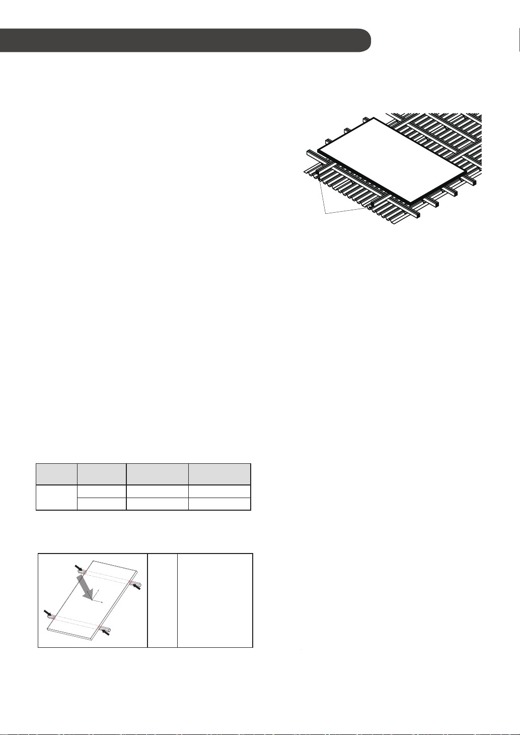
•There is an earth hole on the edge of the module
frame. Using this hole, an earth conductor and the
solar module frame may be recommended to be
connected and earthed as the below drawing.
•All screws and nuts shall be tightened to a torque of
•To prevent electric shock and fire, a protective ground
must be done on the frames of solar modules and arrays
safety class II. The national directives must be respected.
although the solar modules from LG meet the conditions of
4~5 N∙m.
Module frame
Bolt
Flat washer
Star washer
Cup washer
Grounding wire
Spring washer
Nut
Flat washer
Specifications; page 11”.
Parallel configuration is not limited if proper measures
are taken to block the reverse current flow, e.g. fuses
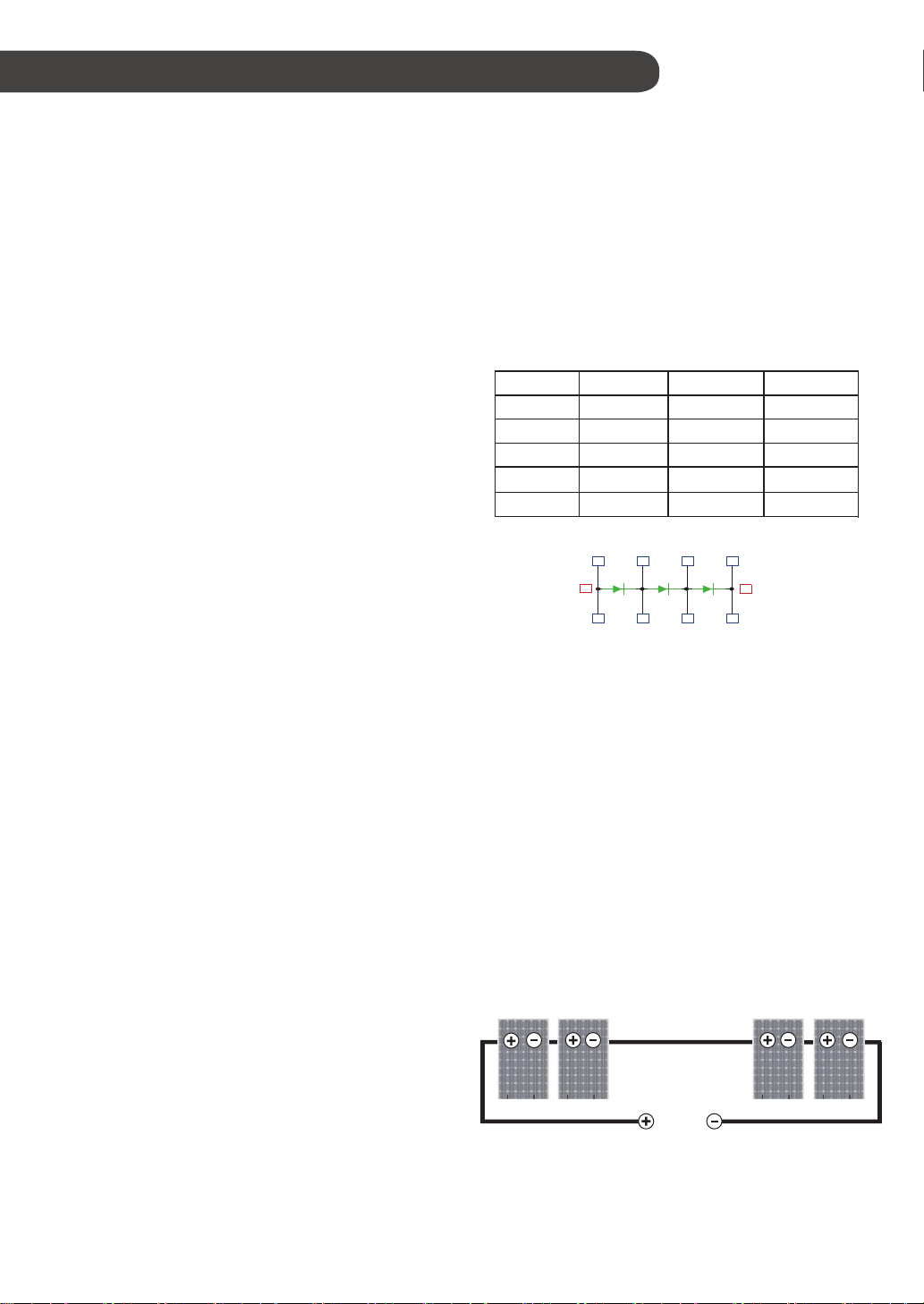
Parallel connection for more current
-+
…………
+-
+
--
+-
+
General Wiring
•LG Electronics recommends that all wiring be double
insulated with a minimum rating of 90°C (194°F).
•
•The minimum size should be determined by the
applicable codes.
•LG Electronics recommends a size no smaller than
4mm .
2
All wiring should use a flexible copper (Cu) conductor.
Specific information on the solar module dimensions
Specifications”.
washer, two flat washers, one cup washer, one star

08
MECHANICAL INSTALLATION
Module Mounting
•The LG Electronics’ (LGE) Limited Warranty for solar
modules is contingent upon modules being mounted
in accordance with the requirements described in this
section.
•The solar modules are in Application Class A and
•Use corrosion resistant material mounting rails and
hardware.
•Use appropriate bolted connections as per
manufacturer’s instructions.
•No electrical parts like cables are located after
installation between laminate and mounting structure.
•LGE solar module is qualified up to a altitude of 4000m.
have the Safety Class II. Therefore they can be
operated in systems with 120V DC and higher.
General access is not restricted.
•We recommend to use mounting device(bolt, nut,
washer) made by corrosion resistant material like
stainless steel.
Site Consideration
LGE solar modules should be mounted in a location that
meets the following requirements.
•Y is a safety factor of 1.5
•Detail of mounting distance is below.
m
Module Strength(Basic Load) ; IEC61215-2:2016
m
Design Load : A
Force
Direction
3600 PascalFront Side
144Cell Rear Side 2000 Pascal
5400 Pascal
3000 Pascal
Test Load : B
(B = A x Y )
Excluded Operating Environments
•
•
The solar modules from LG Electronics can not be
※This mounting method is by using frame bolt holes.
※The mounting rails must run perpendicularly to the module
long side.
operated in a location where they could come in direct
contact with salt water or ammonia.
Shadow
•LGE solar module should be installed in a proper site
that there is no shadowing affected by building,
chimney, tree, and neighboring module, etc.
Mounting
Rails
No. of Cell
Do not use module to replace (or partly replace) roofs
and walls of living places.
Mounting Methods
General Information
•Select the appropriate orientation to maximize sunlight
exposure.
The module generates maximum output power when it
faces the sun directly. The tilt angle of the modules
should be selected to optimize seasonal and sunlight
-based performance in the installation place.
•Module should not be mounted or stored in a way that
the front/top glass faces downward in order to prevent
water from entering the junction box, which could
cause a safety hazard.
•Clearance between the solar module frames and
structures such as roofs or ground is required to
prevent wiring damage and to allow air to circulate
behind the solar module. The recommended standoff
height is a minimum of 100mm.
•When installed on a roof, the solar module must be
is class C after ANSI/UL790 Edition 2004.
the application. The fire resistance of the solar module
mounted over a fire-resistant roof covering rated for
•
•
The solar module is only IEC listed for use when its
factory frame is fully intact.
•
Removal or alteration must be done by an authorized
and qualified individual.
•
Creating additional mounting holes may damage the
solar module and reduce the strength of the frame.
We recommend a 6mm gap between module frames
to avoid tension from thermal expansion.
Module Operating Temperature
•T
•The operating ambient temperature of these devices
may exceed 40℃at full load for all wire sizes if is
determined suitable in the field use application.
emperature range : -40°C ~ 85°C (-40°F ~ 185°F)
①
①
①
①
144Cell
①
: 343mm(N2W)
353mm(N2T)

09
•
•
When installing modules in heavy snow areas,
it is recommended to be taken an appropriate
countermeasure to prevent possible damages to the
lower side frame by slipping snow.
We recommend to use corrosion resistant material
for these supporting part. (A snow guard should be
installed in accordance with the manufacturer’s
instructions.)
Solar module
Roof
Supportingpart
Mounting by using frame bolts holes
•Secure the solar module to the structure by using the
factory mounting holes.
•Four M8 stainless steel bolts, four nuts, four spring
per solar module.
washers, and eight flat washers are recommended
•The module may be fastened to a support by using
both the outer and inner bolt holes of the frame.
•Each module should be securely fastened at a
minimum 4 points on two opposite sides.
•
and location of mounting holes is provided in ‘Product
•Tighten the bolt securely by using the combination.
Place the spring washer between the Flat washer
and Nut.
Mounting by using clamps
•The module may be fastened to a support by using
clamps on both the long edge and the short edge of
the modules.
•
provided in ‘Mechanical Installation Scene’. (Refer to
Appendix.)
→ If you use a special clamp, it needs to test for
compatibility by LGE.
•If the installation is likely to be affected by
heavy(extreme) snow, further suitable panel support is
recommended on the lower row of panels.
•The solar module may be mounted by using the
following methods: (*Torque:8~12N∙m)
* Mounting Rails Material : Aluminum, Stainless steel, etc.
→ We recommend more than 40x40mm mounting rails.
Module frame
Bolt
Flat washer
Flat washer
Spring washer
Nut
Mounting Rail

Disclaimer of Liability
•By beginning to installation process, the installer has to read and completely understand this Installation Manual.
•If installer had any questions regarding this installation manual, the installer would have contacted LG with any
questions or concerns.
•
lunteer and employees, other participants in any activity
connected to installation, operation, or service of LG Solar Modules, and if applicable, from all liabilities, claims,
demands, losses, or damages on my account caused or alleged to be caused in whole or in part by the negligence
and employees.
Disposal
Disposal of your old appliance
1. This crossed-out wheeled bin symbol indicates that waste electrical and electronic products(WEEE)
should be disposed of eparately from the municipal waste stream.
2. Old electrical products can contain hazardous substances so correct disposal of your old appliance
will help prevent potential negative consequences for the environment and human health. Your old
appliance may contain reusable parts that could be used to repair other products, and other valuable
materials that can be recycled to conserve limited resources.
3. You can take your appliance either to the shop where you purchased the product, or contact your local government
waste office for details of your nearest authorized WEEE collection point. For the most up to date information for your
country please see www.lg.com/global/recycling materials that can be recycled to conserve limited resources.
10
DISCLAIMER OF LIABILITY / DISPOSAL
•Do not loosen the banding, when the module is transported by truck, ship and etc.
In case of loose banding, the module will be shaken, which may cause damage.
•Do not stack on more than one pallet. Maximum height is two pallets. Severe stacking can cause stress to the
module and may cause product damage.
•Do not transport only one side of the module when transporting the module. Damage to the frame or cable may occur.
TRANSPORTING AND STORAGE
Date Version Description of change Remark
2020.07.22 1.0 (1st edition) Publish Installation Manual
REVISIONS TABLE

11
PRODUCT SPECIFICATIONS
N-TYPE
Rated electrical characteristic except power rating within -0/+3 percent are within 5 percent of measured.
m/W0001ecnaidarrI:)CTS(noitidnoCtseTdradnatStaseulaV
2
, Cell temp. 25℃, 1.5AM
Electrical Properties Mechanical Properties
Module
Series Model Name Pmax Pmax
at
Bifi100
Pmax
at
Bifi200
at STC
Power
Tolerance
Voc at
STC
Isc at
STC
Vmpp
at STC
Impp at
STC
Max.
Series
Fuse
Rating
Max.
No. of
module
in series
Max.
System
Voltage
Connector Length Width Height Weight
W
%
V A V A A V
mm mm mm
kg
LG430N2W-E6 430 48.6 11.08 40.6 10.60
48.6 11.08 40.6 10.60
48.5 10.82 40.5 10.37
48.8 10.88 40.8 10.42
49.1 10.94 41.1 10.47
49.4 11.00 41.4 10.51
49.7 11.06 41.7 10.56
48.8 11.14 40.9 10.65
48.8 11.14 40.9 10.65
49.1 11.20 41.2 10.70
49.1 11.20 41.2 10.70
49.4 11.27 41.5 10.74
49.4 11.27 41.5 10.74
49.7 11.34 41.8 10.79
49.7 11.34 41.8 10.79
49.9 11.39 42.1 10.83
49.9 11.39 42.1 10.83
50.2 11.45 42.4 10.86
50.5 11.51 42.7 10.89
50.7 11.57 43.0 10.93
50.5 11.51 42.7 10.89
50.7 11.57 43.0 10.93
50.2 11.45 42.4 10.86
0~3% 16 20 1000 2110 1042 40 22
22
22
22
22
22
22
22
22
22
22
22
22
22
22
22
22
22
22
LG435N2W-E6 435 0~3% 16 20 1000 2110 1042 40
LG440N2W-E6 440 0~3% 16 20 1000 2110 1042 40
LG445N2W-E6 445 0~3% 16 20 1000 2110 1042 40
LG450N2W-E6 450 0~3% 16 20 1000 2110 1042 40
LG455N2W-E6 455 0~3% 16 20 1000 2110 1042 40
LG460N2W-E6 460 0~3% 16 20 1000 2110 1042 40
LG455N2W-E6.AW5 455 0~3% 24 20 1500 2110 1042 40
LG460N2W-E6.AW5 460 0~3% 24 20 1500 2110 1042 40
0~3% 16 20 1000 1042 40
0~3% 16 20 1000 1042 40
0~3% 16 20 1000 1042 40
0~3% 16 20 1000 1042 40
0~3% 16 20 1000 1042 40
LG420N2T-E6 420 2130
LG425N2T-E6 425 2130
LG430N2T-E6 430 2130
LG435N2T-E6 435 2130
LG440N2T-E6 440 2130
LGXXXN2W-E6
LG430N2W-E6.AW5 430 0~3% 24 20 1500 2110 1042 40
LG435N2W-E6.AW5 435 0~3% 24 20 1500 2110 1042 40
LG440N2W-E6.AW5 440 0~3% 24 20 1500 2110 1042 40
LG445N2W-E6.AW5 445 0~3% 24 20 1500 2110 1042 40
LG450N2W-E6.AW5 450 0~3% 24 20 1500 2110 1042 40
LGXXXN2W-E6.AW5
LGXXXN2T-E6
MC4 / 05-8
/ PV-CO02
MC4 / 05-8
/ PV-CO02
MC4 / 05-8
/ PV-CO02
MC4 / 05-8
/ PV-CO02
MC4 / 05-8
/ PV-CO02
MC4 / 05-8
/ PV-CO02
MC4 / 05-8
/ PV-CO02
MC4 / 05-8
/ PV-CO02
MC4 / 05-8
/ PV-CO02
MC4 / 05-8
/ PV-CO02
MC4 / 05-8
/ PV-CO02
MC4 / 05-8
/ PV-CO02
MC4 / 05-8
/ PV-CO02
MC4 / 05-8
/ PV-CO02
MC4 / 05-8
/ PV-CO02
MC4 / 05-8
/ PV-CO02
MC4 / 05-8
/ PV-CO02
MC4 / 05-8
/ PV-CO02
MC4 / 05-8
/ PV-CO02
MC4 / 05-8
/ PV-CO02
MC4 / 05-8
/ PV-CO02
MC4 / 05-8
/ PV-CO02
MC4 / 05-8
/ PV-CO02
22LG465N2W-E6 465 0~3% 16 20 1000 2110 1042 40
22
LG470N2W-E6 470 0~3% 16 20 1000 2110 1042 40
22
LG465N2W-E6.AW5 465 0~3% 24 20 1500 2110 1042 40
22
LG470N2W-E6.AW5 470
W
432
437
442
447
452
457
462
457
462
445
455
460
465
470
432
437
442
447
452
467
472
467
472
W
433
438
444
449
454
459
464
459
464
475
485
490
495
500
433
438
444
449
454
469
474
469
474 0~3% 24 20 1500 2110 1042 40
Note) MC4 formal name : PV-KST4 / 6II-UR, PV-KBT4 / 6II-UR
should be selected according to the installation site conditions and local code.
“Max. No. of modules in series” is considering 125% of Voc. Actual number of connections
→ Plus (+) Connector : Male MC4 coupler (PV-KST4/6II-UR)
→ Negative (-) Connector : Female MC4 coupler (PV-KBT4/6II-UR)
Note) The Typical change in module efficiency at 200W/m in relation to 1000W/m is -3.0%
2 2
Note) Max. Bifaciality Coefficient of Power : N2W-E6 0.04 / N2W-E6.AW5 0.04 / N2T-E6 0.70
Max. Bifaciality Coefficient of Current : N2W-E6 0.05 / N2W-E6.AW5 0.05 / N2T-E6 0.70
Max. Bifaciality Coefficient of Voltage : N2W-E6 0.88 / N2W-E6.AW5 0.88 / N2T-E6 0.99
For information about the electrical ratings for both front and back surfaces (Bifaciality Coefficient) and the expected contribution from ground reflected irradiance
along with ground cover and installation height above ground that reflected irradiance, please refer to the sales talk material and datasheet.
Note)
※See more information >> http://www.staubli-alternative-energies.com
http://www.renhesolar.com
http://www.ukt-sz.com
Model Cable Cross Section ØA (Cable outer diameter) Rated current
MC4 4mm²
5.5 ~ 9.0mm 30A
12AWG
05-8 4mm² 5.4 ~ 7.2mm 20A
12AWG
PV-CO02 4mm² 4.0 ~ 7.0mm 20A
12AWG
Ø AØ A
◇Female and male cable couplers ◇
Female cable coupler
Male cable coupler

Model LGXXXN2W-E6 LGXXXN2W-E6.AW5 LGXXXN2T-E6
N
MOT
[
°C
]
Pmax
[
%
/
°C]
Voc
[
%
/
°C]
Isc
[
%
/
°C]
Electrical
Properties(NMOT*)
Model
430
Maximum Power (Pmax)
[
W
]
325
38.2
8.49
45.8
8.92
435
329
38.5
8.53
46.1
8.97
440
332
38.8
8.57
46.3
9.02
445
336
39.1
8.60
46.6
9.08
450
341
39.4
8.64
46.9
9.13
455
344
39.6
8.68
47.1
9.17
460
347
39.9
8.70
47.4
9.22
465
351
40.2
8.72
47.7
9.27
470
355
40.5
8.76
47.9
9.32
MPP Voltage (Vmpp)
[
V
]
MPP Current (Impp)
[
A
]
Open Circuit Voltage (Voc)
[
V
]
Short Circuit Current (Isc)
[
A
]
Model
420
Maximum Power (Pmax)
[
W
]
317
38.1
8.31
45.8
8.71
425
321
38.4
8.35
46.0
8.76
430
325
38.7
8.39
46.3
8.81
435
328
39.0
8.42
46.6
8.86
440
332
39.3
8.46
46.9
8.91
MPP Voltage (Vmpp)
[
V
]
MPP Current (Impp)
[
A
]
Open Circuit Voltage (Voc)
[
V
]
Short Circuit Current (Isc)
[
A
]
Temperature Characteristics
PRODUCT SPECIFICATIONS
*
NMOT (Nominal Module Operating Temperature) : Irradiance 800W/m , ambient temperature 20℃, wind speed 1m/s
2
12
42 ±
3
-0.33
-0.26
0.04
LGXXXN2W-E6
Model
430
Maximum Power (Pmax)
[
W
]
325
38.2
8.49
45.8
8.92
435
329
38.5
8.53
46.1
8.97
440
332
38.8
8.57
46.3
9.02
445
336
39.1
8.60
46.6
9.08
450
341
39.4
8.64
46.9
9.13
455
344
39.6
8.68
47.1
9.17
460
347
39.9
8.70
47.4
9.22
465
351
40.2
8.72
47.7
9.27
470
355
40.5
8.76
47.9
9.32
MPP Voltage (Vmpp)
[
V
]
MPP Current (Impp)
[
A
]
Open Circuit Voltage (Voc)
[
V
]
Short Circuit Current (Isc)
[
A
]
LGXXXN2W-E6.AW5
LGXXXN2T-E6

13
Dimensions of Modules
LGXXXN2W-E6 / LGXXXN2W-E6.AW5
LGXXXN2T-E6
Unit: mm / in.
Note) Cable length with connector (MC4, 05-8, PV-CO02)

14
APPENDIX
Load
Front/Rear(Pa)
Position
(mm)
0~300
962~1062
A
B
1600/1600
5400/3000
Load
Front/Rear(Pa)
Position
(mm)
250 ~ 400 5400/3000
Load
Front/Rear(Pa)
Position
(mm)
250 ~ 400 5400/3000
Load
Front/Rear(Pa)
Position
(mm)
0 ~ 300 5400/1600
Load
Front/Rear(Pa)
Position
(mm)
0~50
100~750
2400/2400
A
B
Fig 1. Bolting type(M8) Fig 2. Clamping Type
Fig 4. Clamping Type
Fig 5. Clamping Type Fig 6. Clamping Type
Mechanical Installation : 72Cell Model
Load
Front/Rear(Pa)
Position
(mm)
N2W: 343
N2T: 353 5400/3000
Fig 3. Clamping Type

15
Fig 11. Clamping Type
Load
Front/Rear(Pa)
Position
(mm)
853 1600/1600
Load
Front/Rear(Pa)
Position
(mm)
712
862
2400/2400
1500/1500
A
Load
Front/Rear(Pa)
Position
(mm)
0~300
250~400
2400/1600
A
B
Load
Front/Rear(Pa)
Position
(mm)
0~50
100~750
2400/2400
A
B
Load
Front/Rear(Pa)
Position
(mm)
250 ~ 400 3000/3000
Fig 10. Bolting type(M6)
Fig 7. Clamping Type Fig 8. Clamping Type
Fig 9. Clamping Type
APPENDIX
Mechanical Installation : 72Cell Model
853

16
EDVybdetsettonerewxidneppasihtnidohtemgnitlobdna)7.giFot1.giF(sdohtemnoitallatsnilacinahcemllA)etoN
It is evaluated by LG internal test.
Module frame
Bolt
Flat washer
Flat washer
Spring washer
Nut
Mounting Rail
•Four M8(5/16inch) stainless steel bolts, four nuts, four spring washers, and eight flat washers are recommended
per solar module.
Bolting Method
Clamp system requirements
•Use corrosion resistant material clamps and hardware.
→.EGLybytilibitapmocroftsetotsdeenti,pmalclaicepsaesuuoyfI
•The clamp should not be touched with the module’s glass.
•
•Use appropriate bolted connections as per clamp manufacturer’s instructions.
•
•Follow the clamp manufacturer’s recommended applied torque to fasten the clamps.
•
<Middle Clamp>
<Edge Clamp>
Width
Height
Depth
Width
Height
Depth

Unloading Flow Guide
If you are unloading using heavy equipment such as a crane, please follow the procedure below.
[ Step 1 ] [ Step 2 ] [ Step 3 ] [ Step 4 ]
Step 1. Place the packaging on a flat surface.
Step 2. Put the safety timber bar on the packaging and fasten a rope as shown Fig. [ Step 2 ]
- To prevent module breakage, you should use safety timber bar bigger than packaging length.
- Detailed view of the rope position is below.
Block ①Block ②Block ②Block ①
Standard Line
Rope
- The position of rope have to be between block 1 and block 2 when you fasten a rope to pallet.
- If you have not timber bar, you can use a pallet which is longer than module size.
- The crane hook have to be placed center of packaging.
- For the balance of packaging, the rope between the packaging and crane must be the same length.
Step 3. Loading & unloading packaging.
- A minimum of two operator is required to ensure that all four corners are seated at the same
time when the packaging is unloaded.
17
Step 4. Landing packaging on a floor.
▶ If you need some question or advice of this, please contact our sales manager.

This document is subject to change without notice.
LG Electronics Inc. (Global HQ)
LG Twin Towers, 128, Yeoui-daero, Yeongdeungpo-gu,
Seoul 07336, Korea
Contact: [email protected]
http://www.lg-solar.com
LG Electronics Deutschland GmbH
Alfred-Herrhausen-Allee 3-5, 65760 Eschborn, Germany
LG, LG logo and Life's Good are trademarks of LG Electronics, Inc. worldwide. Trademarks and
intellectual properties of LG Electronics, Inc. are protected by international copyright laws.
This manual suits for next models
5
Table of contents
Other LG Inverter manuals

LG
LG LG S1C-G3 Series User manual

LG
LG RESU10H Prime User manual

LG
LG SIMs 2.0 User manual

LG
LG LG A1C-A5 Series User manual

LG
LG LGXXXN2W-L5 User manual

LG
LG Mono X Plus Series User manual

LG
LG A1 Series User manual

LG
LG N2T-A5 Series User manual

LG
LG MonoX ACe Assembly instructions

LG
LG LG N1C-V5 Series User manual

LG
LG A005KEEN261 User manual

LG
LG LG A1C-V5 Series User manual

LG
LG LG N3K-V6 Series User manual

LG
LG LG340N1C-A5 User manual

LG
LG ESS Home 10 User manual

LG
LG N1T-L5 Series User manual

LG
LG LGES-5048 User manual

LG
LG LG N1C(W)-L5 Series User manual

LG
LG N2W-L5 Series User manual

LG
LG SV-iC5 Series User manual