Hitachi HTDK150EBS User manual

DVD DIGITAL THEATER SYSTEM
HTDK150EBS
DVD/VCD/CD PLAYER WITH
AV SURROUND RECEIVER
Instruction manual
Manufactured under license from Dolby laboratories. Dolby , Pro Logic and the double D symbol
are trademarks of Dolby Laboratories.
Confidential Unpublished Words. 1992 - 1997 Dolby Laboratories, Inc. All right reserved.
C
" " " "

2
Table of Contents
Important Safeguards and Precautions ............................3~7
Features of This System ........................................................... 8
Conventions about This Manual ............................................. 8
Type of Disc That Can be Played on This System ............... 9
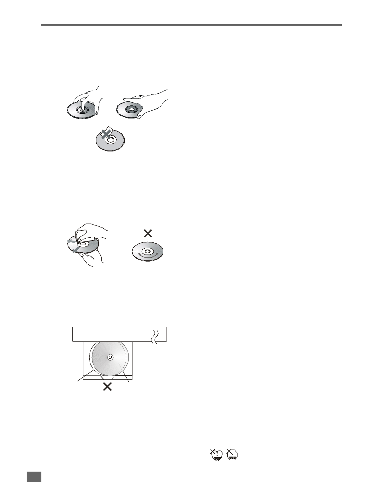
Notes on Discs .........................................................................10
Selecting the Type of Disc for the Connected TV ............... 11
Installations
..........................................12~20
Index to parts and control(Front Panel)................................12
Index to parts and control(Front Panel Display) .................13
Index to parts and control(Rear Panel) ................................14
Index to parts and control(Remote Control)..................15-16
Unpacking .................................................................................17
Inserting Batteries into the Remote Control .......................17
Speaker System Hookup........................................................18
Antenna Hookups ....................................................................19
TV and Optional Component Hookups ................................20
Connecting the AC Power Cord ............................................20
Basic Setup
.............................................21~26
Selecting the Language for OSD ..........................................21
Selecting the Color System ....................................................22
Selecting the Audio Output Mode ..........................................22
Selecting the Video Output Mode ..........................................23
Speakers Setup..................................................................23-25
Presetting Radio Stations ......................................................26
Playing Discs
......................................27~34
Basic Play..................................................................................27
Slow-Motion Play......................................................................28
Single Stepping Play ...............................................................28
Locate a Point Quickly.............................................................28
Skip Next or Previous ..............................................................28
Using the Menu for Each DVD ...............................................29
Playing Video CDs with PBC .................................................30
Repeat Play...............................................................................31
A-B Repeat Play........................................................................31
Program Play ............................................................................32
Selecting a Start Point Using the Time Code .....................33
Selecting a Track Using Number Buttons ...........................33
Checking Information Using Display ...................................34
Settings & Adjustments
..35~44
Using the SETUP Menu ....................................................35-36
SETUP Menu Item List............................................................37
TV Display Setting ....................................................................38
Angle Mark Setting ...................................................................38
Screen Saver Setting ...............................................................38
Center Delay Setting................................................................39
Rear Delay Setting ...................................................................39
Bass Mode Setting...................................................................40
Audio Mode Setting ..................................................................41
Dual Mono Setting....................................................................41
Dynamic Range Setting ..........................................................41
Setting the Language for Audio .............................................42
Setting the Language for Subtitle..........................................42
Setting the Language for Disc Menu ....................................42
Setting the Parental Control Level ........................................43
Setting a New Password ........................................................43
Resetting SETUP .....................................................................44
Special Functions
....................45~48
Picture Zooming .......................................................................45
Angle Selection.........................................................................46
Subtitle Language Selection..................................................46
Audio Language Selection .....................................................46
Using Headphones .................................................................47
Other Functions
............................48~50
Listening to the Radio .......................................................48-49
Listening to an External Source ............................................49
Selecting Listening Modes .....................................................50
Using the Sleep Timer ............................................................50
Additional Information
.51~56
Troubleshooting .................................................................51-53
Glossary...............................................................................53-54
Specifications .....................................................................55-56
2

3
SOME DO
’
S AND DON
’
T ON THE SAFE USE OF YOUR
EQUIPMENT
Thisequipmenthasbeendesignedandmanufacturedtomeetinternationalsafetystandardsbut,like
any electrical equipment, care must be taken if you are to obtain the best results and safety is to be
assured.
•DO read the operating instructions before you attempt to use the equipment.
•DO ensure that all electrical connections(including the mains plug, extension leads and interconnections between pieces of
equipment) are properly made and in accordance with the manufacturer`s instructions. Switch off and withdraw the mains
plug when making or changing connections.
•DO consult your dealer if you are ever in doubt about the installation, operation or safety of your equipment.
•DO be careful with glass panels or doors on the equipment.
•DONTcontinueto operatethe equipmentif youare inany doubtabout itworking normally,or ifit isdamaged inany way-switch
off, withdraw the mains plug and consult your dealer.
•DON T remove any fixed cover as this may expose dangerous voltages.
•DON T leave equipment switched on when it is unattended unless it is specifically stated that it is designed for unattended
operation or has a standby mode. Switch off using the switch on the equipment and make sure that your family knows how to
do this. Special arrangements may need to be made for infirm or handicapped people.
•DON T use equipment such as personal stereos or radios so that you are distracted from the requirements of traffic safety. It
is illegal to watch television whilst driving a vehicle.
•DON T listen to headphones at high volume, as such use can permanently damage your hearing.
•DONTobstructtheventilationopeningsoftheequipment,forexamplewithcurtainsorsoftfurnishings.Overheatingwillcause
damage and shorten the life of the equipment.
•DON T use makeshift stands and NEVER fix legs with wood screws-to ensure complete safety always fit the manufacturer`s
approved stand or legs with the fixings provided according to the instructions.
•DON T allow electrical equipment to be exposed to rain or moisture.
ABOVE ALL
- NEVERletanyoneespeciallychildrenpushanythingintoholes,slotsoranyotheropeninginthe case-thiscould
result in a fatal electrical shock;
- NEVER guess or take chances with electrical equipment of any kind. It is better to be safe than sorry !
3
’
’
’
’
’
’
’
’

4
DECLARATION OF CONFORMITY
We declare under our sole responsibility that this product, to which this declaration relates, is in conformity with the following
standards:
EN60065, EN55013, EN55020, EN61000-3-2 and EN6100-3-3.
Following the provisions of 73/23/EEC, 89/336/EEC and 93/68/EEC directives.
IMPORTANT
Themainsleadonthis equipmentmay besuppliedwithamoulded plugincorporating afuse,thevalueof whichis indicatedon
the pin face of the plug. Should the fuse need to be replaced, an ASTA or BSI approved BS1362 fuse must be used of the same
rating. If the fuse cover is detachable never use the plug with the cover omitted. If a replacement fuse cover is required, ensure
it is of the same colour as that visible on the pin face of the plug. Fuse covers are available from your dealer.
DONOTcutoffthemainsplug fromthisequipment.Iftheplugfitted isnotsuitableforthepowerpoints inyourhomeorthecable
is too short to reach a power point, then obtain an appropriate safety approved extension lead or consult your dealer.
Should it be necessary to change the mains plug, this must be carried out by a competent person, preferably a qualified
electrician.
If there is no alternative to cutting off the mains plug, ensure that you dispose of it immediately, having first removed the fuse, to
avoid a possible shock hazard by inadvertent connection to the mains supply.
IMPORTANT
The wires in this mains lead are coloured in accordance with the following code:
Blue :NEUTRAL
Brown : LIVE
As these colour may not correspond to the coloured markings identifying the terminals in your plug, proceed as follows:
The wire coloured BLUE must be connected to the terminal marked with the letter Nor coloured BLUE or BLACK. The wire
coloured BROWN must be connected to the terminal marked with the letter Lor coloured BROWN or RED.
On no account connect either of these wires to the terminal marked E or by the earth symbol or coloured green or green and
yellow.
Alternatively, this equipment may be supplied with a rewireable plug already fitted, which may be removed if not suitable and an
alternative fitted in accordance with the preceding instructions.
4

5
Welcome!
Thank you for purchasing this DVD Compact AV system.
Beforeoperatingtheunit, please readthisoperation manual
thoroughly and then keep it for future reference as it will be
useful if you have any operation problems in the future.
•This appliance is classified as a CLASS 1 LASER product.
•The CLASS 1 LASER PRODUCT MARKING is located on
the rear panel.
•This product contains a low power laser device. To ensure
continuedsafety donot removeanycoverorattempttogain
access to the inside of the product. Refer all servicing to
qualified personnel only.
CAUTION
Theuseofoptical instrumentwiththisproductwillincrease
eyes hazard. As the laser beam used in this CD/DVD player
is harmful to eyes, do not attempt to disassemble the cabi-
net.
Refer servicing to qualified personnel only.
The following marking is printed on the rear panel.
WARNING
To prevent fire or shock hazard, do not ex-
pose the unit to rain or moisture.
To avoid electrical shock, do not open the
cabinet.
Refer servicing to qualified personnel only.
Mains cord must only be changed at quali-
fied service shop.
This symbol is intended to alert the user of
the presence of uninsulated “dangerous
voltage”withintheproduct
’
sencasementthat
maybe ofsufficientmagnitudetoconstitutea
risk of electric shock to persons.
This symbol is intended to alert the user of
the presence of important operating and
maintenance (servicing) instructions in the
literature accompanying the appliance.
CLASS 1 LASER PRODUCT
KLASSE 1 LASER PRODUKT
LUOKAN 1 LASER LAITE
KLASS 1 LASER APPARAT

6
Important Safeguards and Precautions
•Donotplaceanyobject containingwater orotherliquidson
this unit. In the event that liquid should enter the cabinet,
unplugthis unitimmediatelyandcontacttheretailerorser-
vice centre immediately.
•Do not remove the cabinet. Touching parts inside the cabi-
net could result in electric shock and / or damage to the
unit.
•Do not use the unit in a car. The operation can not be guaran-
teed.
•Do not put subwoofer near TV as this might cause interfer-
ence to TV image.
Nonuse Periods
•When the unit is not being used, turn the unit off.
•When left unused for a long period of time, the unit should
be unplugged from the household AC outlet.
No Fingers or Other Objects Inside
Do not put any foreign object on the disc tray.
Stacking
Place the unit in a horizontal position, and do not place any-
thing heavy on it.
Condensation
Moisture may form on the pickup lens in the following condi-
tions:
•Immediately after a heater has been turned on.
•In a steamy or very humid room.
•When the unit is suddenly moved from a cold environment
to a warm one.
If moisture forms inside this unit, it may not operate properly.
Inthiscase,turnonthepowerand waitaboutonehourforthe
moisture to evaporate.
On adjusting volume
Donotturnupthevolumewhilelisteningtoaportionwithvery
low level inputs or no audio signals. If you do, the speakers
may be damaged when a peak level portion is played.
If There is Noise Interference on the TV While a Broadcast
is being Received
Depending on the reception condition of the TV, interference
may appear on the TV monitor while you watch a TV broad-
castwith theuniton.Thisisnotamalfunctionof theunitorthe
TV. To watch a TV broadcast, turn off the unit.
Service
•Do not attempt to service the unit yourself.
•Please refer any service to the nearest service centre.
Copyright
Audio-visualmaterialmayconsistofcopyrightedworkswhich
mustnotbe recorded withouttheauthority oftheowner of the
copyright. Please refer to relevant laws in your country.
Safeguards
Electrical energy can perform many useful functions. This
unit has been engineered and manufactured to assure your
personal safety. Improper use can result in potential electri-
calshock orfirehazards.Inordernotto defeatthesafeguards,
observethefollowinginstructionsfor itsinstallation, useand
servicing.
Power Cord Protection
To avoid any malfunctions of the unit, and to protect against
electric shock, fire or personal injury, please observe the fol-
lowing:
•When an electric storm is present, unplug the power cord
and disconnect the antenna connections.
•Hold the plug firmly when connecting or disconnecting the
AC power cord.
•Keepthe ACpower cordawayfromtheheatingappliances.
•Never put any heavy object on the AC power cord.
•Donotattempt torepairor reconstructtheAC powercord in
any way.
•Check that all connections are proper and that there are no
problems with the connection cords. Always set the power
to OFF mode before connecting and disconnecting of
the connection cords.
•To prevent short circuits or damaged wires in the connec-
tion cords, always unplug the power cord and disconnect
the connection cords between all other components when
moving the unit.
Location and Handing
•Do not install the system in a confined location; otherwise,
heat dissipation will be poor and malfunctions may occur.
•Alwaysinstall thisunithorizontally.Forproperheatdissipa-
tion, leave at least 10cm of space between the top, back
and sides of this unit and the wall or other components.
•Air vents are provided in the cabinet to prevent excessive
temperaturesinsidetheunit.Donotplacethisunitinclosed
spaces, cover it, or otherwise block the vents.
•Donotplacethisunitindirectsunlight,ornearheatsources.
•Keep this unit away from strong magnetic objects.
•Do not insert or drop anything into this unit through the air
vents as this could cause serious damage, possibly re-
sulting in fire.
STANDBY
OPEN/CLOSE
STOP PLAY/PAUSE
DVD/VCD/CD SURROUNDRECEIVER HTD-K150
PHONES
SELECT
POWER VOLUME
VOLUMEOFF
ON
TUNINGNEXTPREV
10cm or more
10cm or more
10cm or more
*

7
Copy protection
This DVD player supports Macrovision copy protection.
On DVD discs that include a copy protection code, if the con-
tents of the DVD disc are copied using a VCR, the copy pro-
tection code prevents the videotape copy from playing nor-
mally.
RecommendedMeasures forOptimumPictureExcellence
This unit is a precision device that is constructed using ex-
tremely accurate technology.
Soiling or friction affecting the pickup lens or disc drive can
impairtheimagequality. At theworst,neither video nor audio
will be played back. To obtain optimum picture quality, the
playershouldbechecked(cleaningandreplacementofsome
parts)every1,000hours.Notethatthisperiodvariesdepend-
ing on the environment (temperature, humidity, dust, etc..) in
which the player is used.
Do not attempt to clean the pickup lens yourself.
Important Safeguards and Precautions

8
Features of This System
•DVD player built-in DTS*1 and Dolby Digital*2 decoder, supporting Dolby Pro Logic and Virtual Surround.
•5-channel amplifiers attached with active subwoofer.
•Tuner (AM/FM) receiver.
•Conforming DVD, SVCD, VCD1.1, VCD2.0, MP3, CDR, CDRW and CD-DA discs.
•DVD navigation and SVCD, VCD 2.0 PBC controlling functions.
•VFD front panel display and OSD menu display.
•Full function remote control.
*1 Manufactured under license from Digital Theater System, Inc. US Pat. No. 5,451,942 and other worldwide patents issued
and pending. “DTS”and “DTS Digital Surround”are trademarks of Digital Theater Systems, Inc. ©1996 Digital Theater
Systems, Inc. All rights reserved.
*2 Manufactured under license from Dolby Laboratories. “Dolby”, “AC-3”, “Pro Logic”and the double-D symbol are trade-
marks of Dolby Laboratories. Confidential Unpublished Works. ©1992-1997 Dolby Laboratories, Inc. All rights reserved.
Conventions about This Manual
•Instructionsinthismanualdescribethecontrols onthesystem.Youcan alsousethecontrolsontheremotecontroliftheyhave
the same or similar names as those on the system.
•Thetypesoffunctionsandoperationsthatcanbeused foraparticulardiscvary dependingonthefeaturesof thatdisc.Insome
cases,thesefunctionsandoperationsmaydiffer fromthedescriptionsgivenin thisinstructionManual.Inthisevent,follow the
instructions given on the screen. This instruction Manual only covers basic disc operations.
•For some operations, the icon may appear on the screen. This indicates that the operation described in this instruction
Manual is not permitted for the current disc.
•The drawings about the TV screen and front panel display used in this instruction Manual are purely for the purposes of
explanation. The actual displays may differ slightly from what are shown here.

9
This player can playback discs bearing any of the following marks:
Note-1
•DVD players and discs are designed with region numbers
which dictate the regions in which a disc can be played. If
the region number on the disc you want to play does not
matchthe regionnumberinyourDVDplayer,you willnotbe
abletoplaythedisc. Ifyoutrytoplay theDVD,the message
“WRONG REGION”will appear on OSD.
The region number for this DVD player is 2.
On the rear panel of the unit has a region code printed.
Note-2
•Thespecificplayback functionalityforsome DVD andvideo
CDdiscsisdeterminedbythediscmanufacturer.Because
thisDVDplayer playsdisc datainaccordance withthedisc
manufacturer’s guidelines, some functions may not be
available on some discs. Be sure to read the instructions
provided with the disc.
The “Prohibited”icon displayed during DVD player
operation indicates that such manufacturer imposed re-
strictions apply.
Note-3
•The audio on a DVD disc recorded in MPEG version 2.0
format maybe cannot be played (image only).
Discs that Cannot be Played
•You cannot play CD-G, PHOTO CD, CD-ROM and DVD-
ROM discs.
•You cannot play illegally produced discs.
•You cannot play scratched discs.
•You cannot play disc that are dusty, soiled or marked with
fingerprints.
Icons used on DVD discs
Sample Icons:
21. English
2. Chinese 1. English
2. Chinese
216:9 LB 2123
4
5
6
Number of recorded
audio tracks Number of subtitles
recorded Screen aspect
ratio recorded Disc with
Multiple
camera angles
Region code
indicator
Note-4
•DVD door can be opened in DVD function only.
Glossary of Disc Terms
•Title (DVD)
The longest sections of a picture or a music piece on a
DVD; a movie, etc., for a picture piece on a video software;
or an album, etc., for a music piece on and audio software.
Each title is assigned a title number enabling you to locate
the title you want.
•Chapter (DVD)
Sectionsofapictureor amusic piecethataresmallerthan
titles.Atitleiscomposedofseveralchapters.Eachchapter
is assigned a chapter number enabling you to locate the
chapteryouwant. Dependingonthe disc, nochaptersmay
be recorded.
•Track (Video or audio CD)
Sections of a picture or a music piece on a VIDEO or a CD.
Each track is assigned a track number enabling you to lo-
cate the track you want.
Title1
Title 2
For example
Track 1 Track 2 Track 3 Track 4 Track 5
For example
Type of Disc That Can be Played on This System
Sample disc display:
Disc playable in all regions
DVDs
12cm disc / 8cm disc Video CDs
12cm disc / 8cm disc Audio CDs
12cm disc / 8cm disc
See Note-1
See Note-2
See Note-3
See Note-2
•Supports version until version 2.0
•Supports MP3

10
Disc handling precautions
•To keep the disc clean, handle the disc by its edge. Do not touch the surface.
•Do not stick paper or tape on the disc.
If there is glue (or a similar substance) on the disc, remove the glue completely before using the disc.
•Do not expose the disc to direct sunlight or sources such as hot air ducts, or leave it in a car parked in direct sunlight as there
can be considerable rise in temperature inside the car.
•After playing, store the disc in its case.
•Do not write on the label side with a ball-point pen or other writing utensils.
•Be careful not to drop or bend the disc.
Disc cleaning precautions
•Before playing, clean the disc with a cleaning cloth. Wipe the disc from the center out.
•Do not use solvents such as benzine, thinner, commercially available cleaners or anti-static spray intended for vinyl LPs.
Disc installing precautions
•Do not install more than 1 disc on disc tray.
•Do not place the disc on the tray up-side down.
•Do not try to close the disc tray when the disc is not installed properly.
•Do not store discs in high-temperature, high-humidity locations. The discs may develop warps and become unable to play.
Also, discs with moisture on them may be unplayable. Wipe any moisture off with a soft, dry cloth, and be sure discs are fully
dry before using.
•Do not leave a disc inside the CD player when it is not used for a long period.
•Please do not use compact discs with cellophane or with labels attached or those CD with peeled off labels, such as rental
CDs. If such discs are used on a CD player, they may get trapped inside the unit and cause malfunction.
•CD with special shapes (heart-shaped CDs, octagonal CDs etc.) cannot be played on this set.
Attempting to do so may damage the set. Do not use such CDs.
Disc tray Disc
Notes on Discs

11
Both DVD discs and video CDs have the material recorded in the PAL and NTSC systems. Refer to the table below to select the
correct disc type for the type of connected TV.
Connecting to the Multi-system TV
Connecting to NTSC TV
Connecting to PAL TV
Disc
Played in the PAL system.
Played in the NTSC system.
Theuseof amulti-system TV
is recommended.
PAL
NTSC
TV Monitor
Can not be used.
Images playback in black and white. The images may also be
distorted or may overlap at the bottom of the screen.
Played in the NTSC system.
Specify the settings for the type of TV connected (4:3, 16:9).
Disc
PAL
NTSC
TV Monitor
When viewed on a 4:3 TV, the images appear compressed hori-
zontally.
Can not be used.
Images play back in black and white.
Disc TV Monitor
PAL
NTSC
Note
•If the type of disc does not match the type of connected TV, you can also play the disc normally by setting the TV type in the
SETUP menu. For details, see page 21.
Selecting the Type of Disc for the Connected TV

12
Index to Parts and Controls
Refer to the pages indicated in parentheses for details.
Front Panel
10. SELECT button (page 25)
Selects the audio channel to view or adjust its level.
11. VOLUME button (page 25)
Increase the master volume level or the selected chan-
nel level.
12. SOURCE button (page 26, 27, 28, 48, 49)
Selects the component you want to use.
Instandbymode,pressthisbuttontoturnonthepowerof
this system.
13. VOLUME button (page 25)
Decrease the master volume level or the selected chan-
nel level.
14. OPEN/CLOSE button (page 27)
Opens or closes the disc tray.
15. STANDBY LED (page 25, 28)
During standby, this red LED lights.
During mute, this red LED blinks.
1. POWER switch (page 27)
Turns on and off the main power of the system.
2. Disc Tray (page 27)
Place a disc on the tray.
3. REV (TUNING ) button (page 28, 29, 49)
Whileplayinga disc,press thisbuttonto selecttheprevi-
ous title, chapter or track.
Whilelisteningtotheradio,pressthisbuttontodecrease
the frequency. For automatic tuning, press and hold it for
more than 1 second.
4. FWD (TUNING ) button (page 28, 29, 49)
While playing a disc, press this button to select the next
title, chapter or track.
While listening to the radio, press this button to increase
the frequency. For automatic tuning, press and hold it for
more than 1 second.
5. STOP button (page 28)
Stops playing a disc.
6. PLAY/PAUSE button (page 28)
Plays or pauses a disc.
7. REMOTE SENSOR (page 16)
Accepts the remote control signals.
8. Front Panel Display (page 13)
Indicates the playing time, etc..
9. PHONES jack (page 47)
Connects the headphone to this jack.
1 2 3 4 5 6 7 8 9 10 11
15 14 13 12

13
Index to Parts and Controls
Front Panel Display
1213141516 10
9876
5
43
2
1
11
1
Speakers Icon (page 23, 38, 40, 50)
Light according to the selected listening mode and the
type of playing disc.
2
Status Bar (page 26, 30, 33, 48, 49)
It can show the operating information, such as“OPEN”,
“CLOSE”and “LOADING”, etc.
It can show the type of the playing disc, such as“DVD”,
“VCD”, “CD”and“MP3”, etc.
It can show the track and time information of the playing
CD and MP3 disc.
It can show the tuner band and frequency.
It can show the station name and program type when an
RDS station is received.
3
RDS indicator (page 49)
Illuminates when an RDS station is received.
4
PTY (Program Type) indicator (page 49)
Illuminates when an RDS station is received and its PTY
is decoded by the system.
5
Sleep indicator (page 50)
Illuminates when the sleep timer is set to on.
6
Memory indicator (page 25, 31)
Illuminates when the program play mode is set.
Illuminates when presetting radio stations.
7
Mono indicator (page 49)
Illuminates when setting to decode FM signal in mono
mode.
8
Stereo indicator (page 49)
Illuminates when a stereo FM station is received.
9
DTS indicator
Illuminates when the playing disc is recorded with DTS
format.
10
Frequency Unit indicator (page 48, 49)
In AM mode, the“kHz”lights up.
In FM mode, the“MHz”lights up.
11
Wide indicator (page 50)
Illuminateswhenthelistening mode of“ProLogicWide”
or “3-Stereo Wide”is selected.
12
Phan indicator (page 50)
Illuminateswhenthelistening mode of“ProLogicPhan-
tom”is selected.
13
Nor indicator (page 50)
Illuminates when the listening mode of “Pro Logic Nor-
mal”or “3-Stereo Normal”is selected.
14
Dolby 3-Stereo indicator (page 50)
Illuminates when the listening mode of “3-Stereo Nor-
mal”or “3-Stereo Wide”is selected.
15
Dolby Digital indicator
Illuminates when the playing disc is recorded with Dolby
Digital format.
16
Dolby Pro Logic (page 50)
Illuminates when the playing disc is recorded with Dolby
Pro Logic format.
Illuminates when the listening mode of “Pro Logic Nor-
mal”, “Pro Logic Phantom”or “Pro Logic Wide”is se-
lected.

14
Index to Parts and Controls
Refer to the pages indicated in parentheses for details.
Main Unit Rear Panel
1
AM antenna terminal (page 19)
Connects to the supplied AM loop antenna.
2
SCART OUT connector (page 20)
Connects to the TV Scart input terminals.
3
S-VIDEO OUT jack (page 20)
Connects to a TV S-Video input connector.
4
VIDEO OUT jack (page 20)
Connects to a TV Video input connector.
5
SPEAKER output terminals (page 18)
Connects to the supplied speakers.
6
AC power cord (page 18)
Connects to a wall outlet.
(4 )
FL CFR SLSR
12 10 9 8 7
654321
11
FM
(75 )
AM
7
COAXIAL OUT jack (page 20)
Connects to an optional receiver.
8
OPTICAL OUT jack (page 20)
Connects to an optional receiver.
9
AUX1 and AUX2 audio line input jacks (page 20)
Connectsto aTVsetandaVCR,or otheroptionalsource.
10
AUDIO OUT jacks (page 20)
Connects to a TV set, or other stereo receiver.
11
WOOFER LINE OUT jack (page 18)
Connects to the supplied active subwoofer.
12
FM 75 ohm COAXIAL antenna terminal (page 19)
Connects to the supplied FM pigtail antenna.
Subwoofer Rear Panel
1
POWER ON/OFF
Push this switch to ON position to switch on the system.
Pushthisswitch toOFF positiontoswitch offthesystem.
2
AC cord
Connect to a 230V AC power outlet.
3
AUDIO INPUT
Connects the audio source such as amplifier.
4
PHASE (0O-180O)
Thephase relationshipbetweenthesubwooferandmain
speakersmayvarydependingonthecrossoverfrequency
selected and the distance between the subwoofer and
the main speakers.
While listening to music with strong bass content, move
thephaseswitch betweenthe 0Oand 180O position.Leave
theswitchinthepositionthatprovidesthestrongestbass
output.
180Phase0
Audio
Input
ON
POWER
OFF
Serial No.:
14
2
3
SUB WOOFER SYSTEM
MODEL:HTD- K150SUB WOOFER
POWERSUPPLY : 230V~50Hz
IMPEDANCE: 4
POWERCONSUMPTION: 50W
Hitachi,Ltd.Tokyo Japan

15
Index to Parts and Controls
Remote Control
1. STANDBY button (page 28)
Turns on and off the system power.
2. GOTO button (page 33)
Selects a start point to play.
3. Number buttons
Select the items or settings.
4. PROGRAM button (page 32)
Sets a program play.
5. NTSC/PAL button (page 22)
Changes the color system temporarily to match the your
TV standard.
6. STEP(MONO/STEREO) button (page 28, 51)
Do the single stepping play while playing a DVD or VCD.
Switches between monaural or stereo of FM stereo re-
ception.
7. SEARCH / STATION (+ or -) buttons (page 28, 49)
Press to play a disc in fast forward / reverse mode.
In tuner mode, press to select the preset stations.
8. SKIP / TUNING( or ) buttons (page 28, 49)
In DVD player mode, press to select the next / previous
title, chapter or track.
In Tuner mode, press to change the tuning frequency.
Press and hold the button for more than 1 second to
search the station automatically
9. SLOW(MEMORY) button (page 26, 28)
Do the slow-motion play while playing a DVD or VCD.
In tuning mode, press to save as memory preset station
for tuning frequency.
10. STOP button (page 28)
Stops playing a disc and clears the stored program.
11. OPEN/CLOSE button (page 27)
Opens or closes the disc tray.
12. RETURN button (page 30)
Displays the root menu when playing a DVD.
GoesbacktothePBCmenuwhenplayingaVCDorSVCD.
13. REPEAT button (page 31)
Press to do a Repeat 1 or Repeat All playback.
14. A-B button (page 31)
Specifies a section and plays it repeatedly.
15. MUTE button (page 25)
Mutes the sound.
16. LISTENING button (page 51)
Selects a listening mode you want.
17. VOLUME( or )buttons (page 25)
Increase / decrease the master volume level or the se-
lected channel level.
18. SELECT button (page 25)
Selects the audio channel to view or adjust its level.
19. //// ENTER button
Selects and executes the items or settings.
20. AUDIO button (page 47)
Selects the audio channels for sound.
21. SUBTITLE button (page 46)
Selects a desired language for the subtitles while play-
ing a DVD.
22. LANGUAGE button (page 46)
Selects a desired language for the audio when playing a
DVD.
23. DISPLAY button (page 34)
Switches the item displayed on the TV screen or/and on
the front panel display.
1
12
20
23
5
15
11
19
6
17
9
18
16
22
21
2
3
10
7
8
14
13
4
STANDBY
SUB
TITLE
DVD TUNER AUX
LANGUAGE TITLE RETURN
ANGLEGOTO MENU
/PBC
AUDIO
1
DISPLAY
2 3
456
789
+10 0
NTSC/
PAL
VOLUME
SETUP
ENTER
STEP
A-BREPEAT
SLOW
PROG. SELECT
ST/MO
MEMO
ZOOM
SLEEP MUTE
OPEN/
CLOSE
LISTENING
TEST
TONE
SEARCH
TUNING
SKIP
STATION
REMOTE CONTROLLER
RB - HTDK150
STOP PLAY/
PAUSE

16
Index to Parts and Controls
Remote Control
24. DVD button (page 28)
Selects the DVD player mode.
25. ZOOM button (page 45)
Zoom in the playing pictures.
26. SETUP button (page 21, 35)
Displays or exits the SETUP menu.
27. TEST TONE (page 25)
Turns test tone on and off.
28. TUNER button (page 26, 48)
Selects FM or AM mode.
29. AUX button (page 49)
Selects the AUX1 or AUX2 component (i.e. external
source).
30. TITLE button (page 29)
Displays the title menu when playing a DVD.
31. MENU/PBC button (page 30)
SwitchthePBCfunctionsto onor offwhenplayingaVCD
(Ver. 2.0) or SVCD.
32. ANGLE button (page 46)
Changes the angles while playing a DVD.
33. SLEEP button (page 50)
Activates the sleep timer.
34. PLAY/PAUSE button (page 28)
Starts or pauses playing a disc.
24
25
26
27
29
30
32
31
33
34
28
STANDBY
SUB
TITLE
DVD TUNER AUX
LANGUAGE TITLE RETURN
ANGLEGOTO
MENU
/PBC
AUDIO
1
DISPLAY
2 3
4 5 6
7 8 9
+10 0
NTSC/
PAL
VOLUME
SETUP
ENTER
STEP
A-BREPEAT
SLOW
PROG. SELECT
ST/MO
MEMO
ZOOM
SLEEP MUTE
OPEN/
CLOSE
LISTENING
TEST
TONE
SEARCH
TUNING
SKIP
STATION
REMOTE CONTROLLER
RB - HTDK150
STOP PLAY/
PAUSE

17
Unpacking
Check that you have the following items:
•Main unit (1)
•Subwoofer (1)
•Speakers (5)
•Remote control (1)
•Audio & Video cable (1)
•Subwoofer cable (1)
•Scart cable(1)
•Speaker cords (5m x 3, 15m x 2)
•AM loop antenna (1)
•FM pigtail antenna (1)
•Instruction Manual (1)
Inserting Batteries into
the Remote Control
You can control the system using the supplied remote con-
trol.Inserttwo batteriesbymatching the+and -on the batter-
ies. When using the remote control, point it at the remote
sensor on the front panel of this system.
3V[2X “AAA cell OR IEC R3 OR JIS R3P (JIS SUM-4)]
Note
•Donotleavetheremotecontrolinanextermelyhot orhumid
place.
•Do not use a new battery with an old one.
•Do not drop any foreign object into the remote casing. Par-
ticularly when replacing the batteries.
•Do not expose the remote sensor to direct sunlight or light-
ing apparatus. Doing so may cause a malfunction.
•If you are not using the remote control for an extended pe-
riod of time, remove the batteries to avoid possible dam-
age from battery leakage and corrosion.
•The remote control may not be effective in strong day-
light.
•During radio listening (AM), if you operate the remote con-
trolextremely closeto thesystem,somenoisemaybepro-
duced.
STANDBY
SUBTITLE DVD TUNER AUX
LANGUAGE TITLE RETURN
ANGLEGOTO MENU/PBC AUDIO1DISPLAY
2 3
4 5 6
7 8 9
+10 0NTSC/
PAL
VOLUME
SETUP
ENTER
STEP
A-BREPEAT SLOW
PROG. SELECT
ST/MO
MEMO
ZOOM
SLEEP MUTE
OPEN/
CLOSE
LISTENING
TEST
TONE
SEARCH
TUNING
SKIP
STATION
REMOTE CONTROLLER
RB-HTDK150
STOP PLAY/PAUSE
ST
ANDB
Y
SUB
TITL
E
DVD
TUNER
AUX
LA
NGUAG
ET
ITLERE
TURN
ANG
LE
G
O
TOM
ENU
/PBC
AUDIO
1
DIS
PLAY
23
456
789
+1
00
N
TSC
/
P
AL
V
O
LUM
E
SET
UP
ENTER
S
TEP
A-B
REPE
ATSLO
W
PROG
.SELECT
S
T/M
O
M
E
MO
ZO
OM
SLEEP
M
UTE
O
PE
N/
C
LOSE
LISTENING
TES
T
TONE
SEAR
CH
TU
NING
SKIP
S
TATIO
N
RE
M
O
TEC
O
NT
ROLLER
RB-
HTDK150
STO
PPLAY/
PA
USE
STAN
DBY
SUB
TITL
EDVDTUNE
RAUX
LANG
UAGETIT
LERETURN
ANGLE
G
OTOMENU
/PBC
AUDIO
1DISP
LAY
23
4
5
6
7
8
9
+100
NTSC
/
PAL
V
O
LUM
E
SETUP
EN
TER
ST
EP
A-B
REPE
ATS
LOW
PRO
G
.
SELEC
T
ST/M
O
M
EM
O
Z
O
OM
SLEEPM
UTE
O
PE
N/
C
LO
SE
LISTENING
TEST
TONE
SEARCH
TUNING
SKIP
STATION
R
EM
O
TEC
ONT
RO
L
LER
R
B-HTDK150
STO
PP
LAY/
PAUSE
STANDBY
OPEN/CLOSE
STOP PLAY/PAUSE
DVD/VCD/CD SURROUND RECEIVER HTD-K150
PHONES
SELECT
POWER VOLUME
VOLUME
OFF
ON
TUNING
NEXTPREV
6m
30o30o
Installations
This section describes how to hookup the system to
the speakers, a TV monitor with audio / video input
jacksandother videocomponent.You cannotconnect
this system to a TV monitor which does not have a
video input connector. Be sure to turn off the power of
each component before making the connections.

18
Speaker System Hookup
Connect the supplied speaker system using the supplied
speaker cords by matching the colors of the terminals and
those of the cords.
At the rear of each supplied speakers you will find two click
fixationconnectors,ablackoneisfor(-)andared/blue/grey
one is for (+).
•Connect the active Subwoofer to the RCA jack of WOOFER
LINE OUT.
Required subwoofer cable (supplied):
•Connect the Front Left speaker to the FL terminals.
•Connect the Front Right speaker to the FR terminals.
•Connect the Center speaker to the C terminals.
•Connect the Surround Left speaker to the SL terminals.
•Connect the Surround Right speaker to the SR terminals.
Required speaker cords (supplied):
To avoid short-circuiting the speakers
•Short-circuiting of the speakers may damage the system.
Topreventthis,makesuretotakethefollowingprecautions
when connecting the speakers.
•Make sure the stripped end of each speaker cord does not
touch another speaker terminal or the stripped end of an-
other speaker cord.
Examples of poor conditions of the speaker cord
•Stripped speaker cord is touching another speaker termi-
nal.
•Stripped cords are touching each other due to excessive
removal of insulation.
Note
•Besuretomatchthe speakercord totheappropriatetermi-
nal on the components: + to + and - to -. If the cords are
reversed, the sound will be distorted and will lack bass.
•If you use front speakers with low maximum input rating,
adjustthevolumecarefullytoavoidexcessiveoutputonthe
speakers.
Black Black
+
+
FR CFL SR SL
(4 )
AM
FM
(75 )
Front Right Speaker
Front Left Speaker
Center Speaker
Rear Surround Right Speaker
Rear Surround Left Speaker
Active Subwoofer
+
+
++
180
POWER
ON
OFF
Phase0
Audio
Input
AC120V~60Hz
Speakers
FRONT (L&R)
CENTER
(REAR) SURROUND (L&R)
BLACK
BLACK
BLACK
RED
BLUE
GREY
+

19
Antenna Hookups
Connect the supplied AM / FM antennas for listening to the radio.
•Connect the AM loop antenna to the AM terminals.
•Connect the FM pigtail antenna to the FM 75-ohm coaxial terminal.
Note
•To prevent noise pickup, keep the AM loop antenna away
from the system and other components.
•Be sure to fully extend the FM pigtail antenna.
•Afterconnecting theFM pigtailantenna,keepitashorizontal
as possible.
Skill of connecting antenna and speaker wires
Push and hold Speaker terminal tab down to insert wire. Re-
lease tab to lock wire in terminal. Make sure the insulation is
completelyremovedfromtheendsoftheAntennaandspeaker
wires at all connection points.
If you have poor FM reception
Use a 75-ohm coaxial cable (not supplied) to connect the
system to an outdoor FM antenna as shown below.
Note
•If you connect the system to an outdoor antenna, ground it
against lightning.
•To prevent a gas explosion, do not connect the ground wire
to a gas pipe.
AM
FM
(75 )
Outdoor FM antenna
System
To ground
Ground wire
(not supplied)
FR CFL SR SL
(4 )
FM
(75 )
FM wire antenna
(supplied)
AM wire antenna
(supplied)
AM

20
TV and Optional Compo-
nent Hookups
Required cords
•Video cord for connecting a TV set (supplied).
•Audio cords (supplied).
When connecting a cord, be sure to match the color-coded
pins to the appropriate jacks on the components.
Note
•When using the S-VIDEO OUT jack instead of the VIDEO
OUT jack for better picture clarity.
Your TV monitor must also be connected via an S-VIDEO
INPUT jack. S-Video signals are on a separate bus from
the video signals and will not be output through the video
jacks.
•When using the SCART OUT connector instead of the
VIDEO OUT jack.
YourTVmonitormustalsobeconnectedviaanScartsocket.
The Scart terminal contains separate video signals and
stereo audio signals.
•You can connect the OPTICAL or COAXIAL output to an-
other amplifier with DTS, Dolby Digital decoder.
Connecting the AC Power
Cord
Note
•Power Requirements: AC 230 V, 50Hz.
•The power that differs from above value will damage the
system or cause the system to work abnormally.
BeforeconnectingtheAC power cord(mainlead) of this sys-
tem to a wall outlet, connect the speakers to the system.
Connect the AC power cord of the active subwoofer.
ConnecttheACpowercords(mainleads)ofyourTV,optional
components to a wall outlet.
Yellow Yellow
Red
White White
Red
FR CFL SR SL
(4 )
AM
FM
(75 )
Other manuals for HTDK150EBS
1
Table of contents
Other Hitachi Home Theater System manuals

Hitachi
Hitachi HTD-K180UK User manual

Hitachi
Hitachi HTD-K180UK User manual

Hitachi
Hitachi HTD-K160 User manual

Hitachi
Hitachi HTD-K160 User manual

Hitachi
Hitachi HTDK170EUK User manual

Hitachi
Hitachi L32R200 User manual

Hitachi
Hitachi HTD-K180UK User manual

Hitachi
Hitachi HTD-K160 User manual

Hitachi
Hitachi HTD-K200E User manual

Hitachi
Hitachi DV-S522U User manual