manuals.online logo
Brands
  1. Home
  2. •
  3. Brands
  4. •
  5. Hitachi
  6. •
  7. Impact Driver
  8. •
  9. Hitachi WR 22SE User manual

Hitachi WR 22SE User manual

PRODUCT NAME
Hitachi Impact Wrench
Model WR 22SE
LIST No.
xxx. 2014
REPAIR GUIDE ----------------------------------------------------------------------------------------------------------------- 1
1. Precautions on disassembly and reassembly------------------------------------------------------------- 1
STANDARD REPAIR TIME (UNIT) SCHEDULE ----------------------------------------------------------------------10
CONTENTS
Overseas Sales Division
LIST No.
WR 22SE: E729
Jan. 2015
W
-1-
Fig. 1 • Disassembly of hammer case (D) ass’y
WARNING: Be sure to turn off the power switch and disconnect the power cord plug from the
power supply before conducting repair.
1. Precautions on disassembly and reassembly
[Bold] numbers in the description below correspond to the item numbers in the Parts List and exploded
assembly diagram for the Model WR 22SE.
1. Disassembly of hammer case (D) ass’y
(1) Removal of hammer case (D) ass’y
Remove the Button Bolt M4 [44] and four Bolts M5 x 45 [3]. Supporting Hammer Case (D) Ass’y [1],
tap the tip of the Anvil [9] with a wooden hammer to remove Hammer Case (D) Ass’y [1]. Remove
Packing (D) [26] from between Hammer Case (D) Ass’y [1] and Inner Cover (D) [27].
(2) Removal of the anvil
Remove the Anvil [9] from the bearing portion of Hammer Case Ass’y (D) [1].
(3) Removal of the ring gear
Tap the end surface of Hammer Case Ass’y (D) [1] with a wooden hammer to remove the Ring Gear
[23]. If the Ring Gear [23] cannot be removed, warm up Hammer Case (D) Ass’y [1] and tap it with a
wooden hammer to remove the Ring Gear [23].
SELLING POINTS
Disassembly
REPAIR GUIDE
[2]
[3]
[1]
[6]
[7] [8]
[9]
[22]
[23]
[26]
[27]
[16]
[17]
[18]
[9]
[38]
[37]
[44]
-2-
Fig. 2
Fig. 3
2. Removal of the spring
Using a hand press, push down the raised portions of Hammer (D) [11] to compress the Spring [14] fully.
In this position, use a small flat-blade screwdriver to extract the two Steel Balls D7.14 [10] from the cam
grooves of the Spindle [20] and Hammer (D) [11]. Then slowly release the hand press and remove
Hammer (D) [11] from the Spindle [20] to remove the Spring [14].
NOTE: Be careful not to lose the thirty-eight Steel Balls D3.97 [12] and the Hammer Washer [13]
mounted between Hammer (D) [11] and the Spring [14].
[10]
[11]
[12]
[13]
[14]
[15]
[19]
[20]
[21]
[20]
[11]
[10]
Raised portion of the hammer
Top of the spindle cam
Steel ball guide groove
-3-
Fig. 4 • Disassembly of the motor unit
Fig. 5
3. Disassembly of the motor unit
(1) Removal of rotor ass’y (D)
Remove Rotor Ass’y (D) [29] together with Inner Cover (D) [27] from Housing (D) [34].
NOTE: Keep the removed Rotor Ass’y (D) [29] away from iron or other metal because Rotor
Ass’y (D) [29] has a magnetic force.
(2) Remove the two Screws D4 x 60 [32], Screw D4 x 35 [37], and two Screws D4 x 16 [46]. Then remove
the power supply unit.
[36]
[27]
[28]
[29]
[30]
[31]
[34]
[38]
[37]
[44]
[46]
[47]
[32]
[33]
[34]
[50]
-4-
Fig. 6 • Removal of the switch
4. Removal of the switch
Remove the four Screws M3.5 x 5 [40] from the Switch [39] and remove the Switch Adapter [41]. Then
remove the Switch [39].
[37]
[38]
[39]
[40]
[41]
[34]
[44]
[43]
-5-
Fig. 7 • Disassembly of the power supply unit
5. Disassembly of the power supply unit
(1) Remove the four Screws M3.5 x 5 [40] from the Switch [39].
(2) Hold the Switch Adapter [41] and slowly pull it out.
Internal wire (black)
Internal wire (white) Internal wire (black)
[39]
Sensor PCB ass’y
[49]
[48]
Filter PCB ass’y
[45]
Noise suppressor PCB ass’y
Main PCB ass’y
Internal wire (white)
[43]
[42]
[42] [42]
[41]
[40]
Internal wire (red)
-6-
Fig. 8 • Reassembly of the power supply unit and its vicinity
Perform reassembly by reversing the disassembly procedure. However, special attention should be given
to the following items.
1. Reassembly of the power supply unit and its vicinity
(1) Perform wiring according to the connecting diagram on page 9 when replacing the Switch [39] or Stator
Controller (D) Set [33] with new one.
(2) Connect the internal wires of Stator Controller (D) Set [33] to the Switch [39] paying attention to the
colors of the internal wires. Then secure them with the four Screws M3.5 x 5 [40].
(3) Be careful not to get the internal wires caught in the power supply unit.
2. Reassembly of the impact mechanism
(1) Mount the Hammer Washer [13], Spring [14], Spring Seat [15], and Spindle [20] in this order into
Hammer (D) [11], which contains the thirty-eight Steel Balls D3.97 [12].
(2) Match the peak of the cam groove of the Spindle [20] with the steel ball insertion groove of Hammer
(D) [11]. Use a hand press or similar tool to press the raised portion of Hammer (D) [11] so as to
compress the Spring [14] until it contacts the Spindle [20], and then hold it there.
(3) Put the two Steel Balls D7.14 [10] in the steel ball insertion groove. Check that the Steel Balls D7.14
[10] are in the cam groove, and then release the hand press.
(4) Mount the Idle Gear Set (2 pcs.) [21] and the two Gear Shafts [19] on the Spindle [20].
3. Reassembly of the main body
(1) Secure the stator to Housing (D) [34] with the two Screws D4 x 60 [32] and insert the controller PCB
ass’y (D) into the lower portion of the stator.
(2) Mount the Cord Clip [47] with its protrusion toward the cord, and then secure it with the two Screws D4
x 16 [46].
(3) Position the internal wires under the Switch [39].
NOTE: Position the internal wire of the noise suppressor PCB on the right, and the internal wire
of the power supply PCB on the left. Position the green and yellow internal wires of the
switch on the right, and the blue and black internal wires on the left. Then insert the
Switch [39].
Reassembly
B
Internal wire
(
black
)
Internal wire (yellow)
Internal wire (green)
Internal wire (blue)
[39]
[40]
View from B
-7-
Mount Washer (F) [8] with its
chamfered side toward the anvil.
Fig. 9 • Reassembly of the main body
Fig. 10 • Reassembly of the main body
(4) Mount Rotor Ass’y (D) [29] and Fan Guide (D) [31] to Housing (D) [34].
NOTE: Be careful of the direction of Fan Guide (D) [31].
(5) Secure Handle Cover (D) [38] to Housing (D) [34] with the Screw D4 x 35 [37].
(6) Mount Metal (E) [25] and Packing (D) [26] to Inner Cover (D) [27].
NOTE: Do not mount Packing (D) [26] upside down.
(7) Mount Washer (E) [24] and Ring Gear [23] to the impact mechanism and mount it to Inner Cover (D)
[27].
NOTE: Mount the Ring Gear [23] with its protrusion toward the hammer case.
(8) Mount Washer (F) [8] to the Anvil [9]. Apply a small amount of grease to the Needle Roller [22] and
mount it to the Ring Gear [23].
(9) Insert Washer (D) [6] and Damper (D) [7] into Hammer Case (D) Ass’y [1] and secure it with the four
Bolts M5 x 45 [3].
(10) Secure Handle Cover (D) [38] and Hammer Case (D) Ass’y [1] with the Button Bolt M4 [44].
Position the noise suppressor PCB in the
stator holder (D) as shown in the figure.
White internal wire
(Power supply unit)
Black internal wire
(Power supply unit)
White internal wire
(Noise suppressor)
-8-
(1) Apply Nippeco SEP-3Agrease (Code No. 930035 (100 g)/930038 (2.5 kg)) to the following:
•Pinion tooth flanks of Rotor Ass’y (D) [29]
•Tooth flanks of the Ring Gear [23]
•Two Gear Shafts [19]
•Tooth flanks and inner circumference of the Idle Gear Set (2 pcs.) [21]
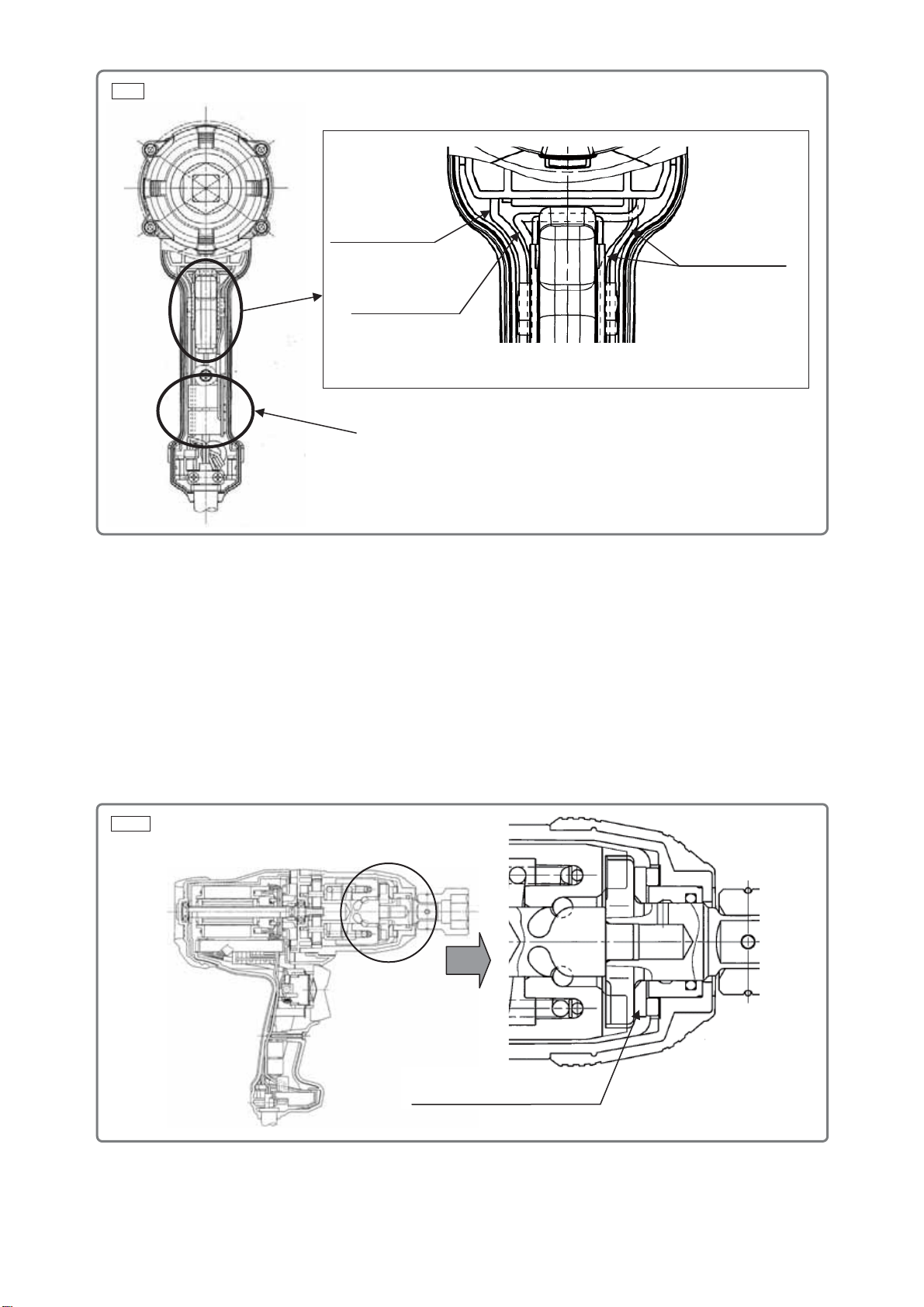
(2) Apply Doubrex 251 grease to the following:
•Between Hammer (D) [11] and Spring Seat [15]
•Inside of Hammer Case (D)Ass’y [1]
•Spindle [20]: Cam groove, sliding portion, and engaging portions with the Anvil [9] and Metal (E) [25]
•Cam groove and raised portions of Hammer (D) [11]
•Anvil [9]: 13 mm dia. hole, sliding portion with Washer (F) [8], claw, and sliding portion with the O-ring
•Two Steel Balls D7.14 [10]
•Thirty-eight Steel Balls D3.97 [12]
•Both end surfaces of Washer (D) [6] and Damper (D) [7]
•Seal Lock Hex. Socket Hd. Bolt M5 x 45 [3]----------------------------7.8 ± 1.5 N•m (80 ± 15 kgf•cm)
•Tapping Screw (W/Flange) D4 x 35 (Black) [37]-----------------------2.0 ± 0.5 N•m (20 ± 5 kgf•cm)
•Hex. Hd. Tapping Screw D4 x 60 [32] ------------------------------------2.0 ± 0.5 N•m (20 ± 5 kgf•cm)
•Button Bolt M4 [44]------------------------------------------------------------1.8 ± 0.4 N•m (18 ± 4 kgf•cm)
•Tapping Screw (W/Flange) D4 x 16 [46]---------------------------------2.0 ± 0.5 N•m (20 ± 5 kgf•cm)
Check the following after reassembly:
(1) Operate the Switch [39] and check that the switch moves smoothly and the switch operations (ON,
OFF, forward and reverse) are normal.
(2) Press the Switch [39] in “R” direction and slowly release the switch. Check that the switch returns to
the original position. Then press the Switch [39] in “L” direction and slowly release the switch. Check
that the switch returns to the original position.
(3) Check that the rotational direction of Anvil [9] matches the direction of rotation made when you press
the Switch [39]. When the Switch [39] is set to the “R” position, the Anvil [9] must rotate clockwise as
viewed from the rear (opposite to the Anvil [9].)
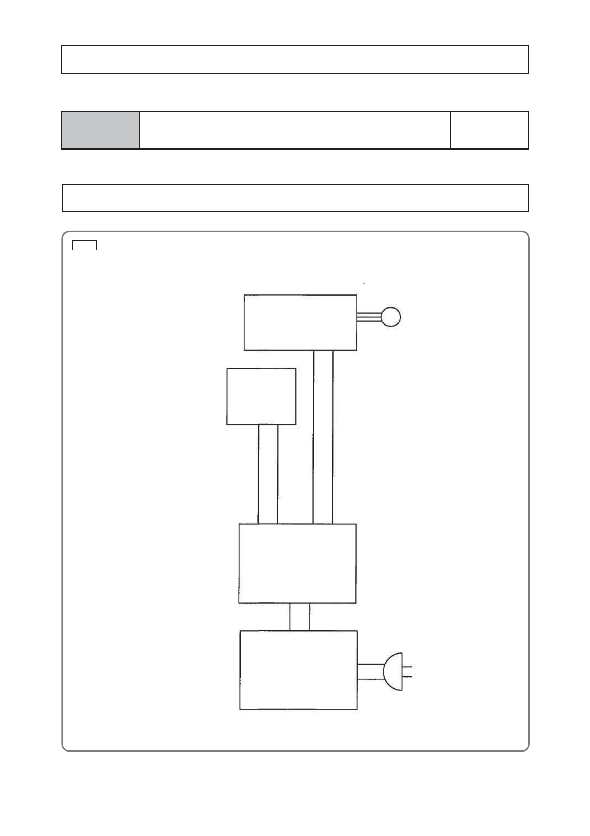
On completion of reassembly after repair, measure the insulation resistance and conduct the dielectric
strength test between the plug pins and the outside metallic parts such as the Anvil [9].
Insulation resistance: 7 Mȍor more
Dielectric strength: 2,500 V for 1 minute --------------------------------------- 110 V to 120 V
4,000 V for 1 minute --------------------------------------- 220 V to 240 V
Screw tightening torque
Checking after reassembly
Application of lubricant
Insulation test
-9-
Fig. 11 • Connecting diagram
M
Sensor PCB ass’y
Switch [39]
Main PCB ass’y
Filter PCB ass’y
After no-load operation for 30 minutes, the no-load current value should be as follows.
Voltage 110 V 120 V 220 V 230 V 240 V
Current max. 3.5 A 3.5 A 1.5 A 1.5 A 1.5 A
No-load current
Connecting diagram
-10-
MODEL Variable
Fixed 10 20 30 40 50 60 min.
WR 22SE
General Assembly
Work Flow
Handle
Cover (D)
Switch
Adapter
Cord Armor
Tail
Bumper (D)
Switch
Cord
Rotor
Ass'y (D)
Ball Bearing
(6000DD)
Ball Bearing
(608VV)
Inner
Cover (D)
Hammer (D)
Steel Ball
D7.14 x 2
Steel Ball
D3.97 x 10
Spring
Spring Seat
Hammer
Case (D)
Ass’y
O-ring
Anvil
Ring Gear
Housing (D)
Stator
Controller
(D) Set
Spindle
Idle Gear Set
Gear Shaft
x 2
STANDARD REPAIR TIME (UNIT) SCHEDULE
Model WR 22SE
IMPACT WRENCH
LIST NO. E729
2015·1·20
(E1)
7
8
50
1
2
3
4
5
6
9
10
11
12 13
14
15
16
17
18
9
19
20
21 22
23
24
25
26
27
28 29
30
31
32
33
37
38
39
41
34
35
36
45
46 47
48
49
501
505
502
503
504
506
40
42
43
42
42
43
44
PART
S
WR 22SE
DESCRIPTION REMARKS
1 337849 HAMMER CASE (D) ASS'Y 1 INCLUD.2,4,5
2 337850 BUMPER (D) 1
3 323994 SEAL LOCK HEX. SOCKET HD. BOLT M5 X 45 4
4 971028 O-RING (P-28) 1
5 337851 METAL (F) 1
6 338357 WASHER (D) 1
7 338356 DAMPER (D) 1
8 337848 WASHER (F) 1
*9 324013 ANVIL (A) 1
*9 324021 ANVIL (B) ASS'Y 1 INCLUD.16-18 FOR AUS,USA,CAN
10 959151 STEEL BALL D7.14 (10 PCS.) 2
11 338358 HAMMER (D) 1
12 959155 STEEL BALL D3.97 (10 PCS.) 38
13 324004 HAMMER WASHER 1
14 324002 SPRING 1
15 324001 SPRING SEAT 1
*16 949507 ROLL PIN D2 X 14 (10 PCS.) 1 FOR AUS,USA,CAN
*17 992571 SPRING 1 FOR AUS,USA,CAN
*18 992572 PLUNGER 1 FOR AUS,USA,CAN
19 971016 GEAR SHAFT 2
20 324003 SPINDLE 1
21 318448 IDLE GEAR SET (2 PCS.) 2
22 991449 NEEDLE ROLLER 1
23 985303 RING GEAR 1
24 337847 WASHER (E) 1
25 337846 METAL (E) 1
26 337842 PACKING (D) 1
27 337845 INNER COVER (D) 1
28 6000DD BALL BEARING 6000DDCMPS2L 1
29 360990 ROTOR ASS'Y (D) 1 INCLUD.28,30
30 333945 BALL BEARING 608VV 1
31 337844 FAN GUIDE (D) 1
32 960108 HEX. HD. TAPPING SCREW D4 X 60 2
*33 340897C STATOR CONTROLLER (D) SET 110V 1
*33 340897D STATOR CONTROLLER (D) SET 120V-127V 1
*33 340897E STATOR CONTROLLER (D) SET 220V-230V 1
*33 340897F STATOR CONTROLLER (D) SET 240V 1
34 338355 HOUSING (D) 1
35 NAME PLATE 1
36 337843 TAIL BUMPER (D) 1
37 303694 TAPPING SCREW (W/FLANGE) D4 X 35 (BLACK) 1
38 337841 HANDLE COVER (D) 1
39 337202 SWITCH 1
40 980060 MACHINE SCREW (W/WASHER) M3.5 X 5 4
41 323768 SWITCH ADAPTER 1
42 338354 CUSHION RUBBER 45 X 10 X 3 6
43 338353 CUSHION RUBBER 30 X 10 X 3 3
44 338500 BUTTON BOLT M4 1
45 959140 CONNECTOR 50091 (10 PCS.) 2
46 984750 TAPPING SCREW (W/FLANGE) D4 X 16 2
- 2 - 1 - 15*ALTERNATIVE PARTS
ITEM
NO. NO.
USED
CODE NO.
PART
S
WR 22SE
DESCRIPTION REMARKS
47 937631 CORD CLIP 1
*48 953327 CORD ARMOR D8.8 1
*48 938051 CORD ARMOR D10.1 1
*49 500247Z CORD 1 (CORD ARMOR D8.8)
*49 500423Z CORD 1 (CORD ARMOR D8.8) FOR MAL,
SIN (230V),UAE (230V)
*49 323974 CORD 1 (CORD ARMOR D10.1) FOR TPE,
SIN (110V),UAE (110V)
*49 500234Z CORD 1 (CORD ARMOR D8.8) FOR INA,IND
*49 500439Z CORD 1 (CORD ARMOR D8.8) FOR AUS,NZL
*49 500240Z CORD 1 (CORD ARMOR D8.8) FOR USA,CAN
*49 500450Z CORD 1 (CORD ARMOR D8.8) FOR GBR (230V)
*49 500461Z CORD 1 (CORD ARMOR D8.8) FOR GBR (110V)
*49 500248Z CORD 1 (CORD ARMOR D8.8) FOR SUI
*49 500496Z CORD 1 (CORD ARMOR D8.8) FOR CHN
*49 500475Z CORD 1 (CORD ARMOR D8.8) FOR KOR
*49 500487Z CORD 1 (CORD ARMOR D8.8) FOR BRA
*50 323210 BOLT WASHER M4 (BLACK) 1 FOR 220V-240V
1 - 15 - 3 -*ALTERNATIVE PARTS
NO.
USED
CODE NO.
ITEM
NO.
WR 22SE
DESCRIPTION REMARKS
501 338326 CASE 1
502 338327 SIDE HANDLE ASS'Y 1 INCLUD.503-506
503 330209 SIDE HANDLE 1
504 323775 HANDLE HOLDER 1
505 338498 HANDLE RING 1
506 980903 SQUARE BOLT M8 1
DESCRIPTION REMARKS
601 874535 EXTENSION BAR ASS'Y (SQUARE) 19.0MM X 150L 1 INCLUD.602,603
602 874524 SOCKET RING 1
603 874525 SOCKET PIN 1
604 955088 UNIVERSAL JOINT ASS'Y 1 INCLUD.602,603
605 955091 UNIVERSAL JOINT PIN 1
606 986004 ADAPTER ASS'Y 12.7MM 1 INCLUD.602,603
607 874527 HEX. SOCKET ASS'Y 23MM X 55L 1 INCLUD.602,603
608 874528 HEX. SOCKET ASS'Y 24MM X 55L 1 INCLUD.602,603
609 874529 HEX. SOCKET ASS'Y 26MM X 55L 1 INCLUD.602,603
610 874530 HEX. SOCKET ASS'Y 27MM X 55L 1 INCLUD.602,603
611 874532 HEX. SOCKET ASS'Y 30MM X 55L 1 INCLUD.602,603
612 874523 HEX. SOCKET ASS'Y 32MM X 55L 1 INCLUD.602,603
613 874533 HEX. SOCKET ASS'Y 35MM X 55L 1 INCLUD.602,603
614 874534 HEX. SOCKET ASS'Y 36MM X 55L 1 INCLUD.602,603
615 955028 HEX. SOCKET ASS'Y (LONG) 17MM X 60L 1 INCLUD.602,603
616 955029 HEX. SOCKET ASS'Y (LONG) 19MM X 60L 1 INCLUD.602,603
617 955030 HEX. SOCKET ASS'Y (LONG) 21MM X 60L 1 INCLUD.602,603
618 955031 HEX. SOCKET ASS'Y (LONG) 22MM X 60L 1 INCLUD.602,603
619 955033 HEX. SOCKET ASS'Y (LONG) 24MM X 60L 1 INCLUD.602,603
620 955034 HEX. SOCKET ASS'Y (LONG) 26MM X 85L 1 INCLUD.602,603
621 955035 HEX. SOCKET ASS'Y (LONG) 27MM X 85L 1 INCLUD.602,603
622 955037 HEX. SOCKET ASS'Y (LONG) 30MM X 85L 1 INCLUD.602,603
623 955038 HEX. SOCKET ASS'Y (LONG) 32MM X 100L 1 INCLUD.602,603
624 955092 HEX. SOCKET ASS'Y (LONG) 36MM X 100L 1 INCLUD.602,603
- 4 - Printed in Japan 1 - 15
(150120N)
*ALTERNATIVE PARTS
OPTIONAL ACCESSORIES
STANDARD ACCESSORIES NO.
USED
NO.
USED
CODE NO.
CODE NO.
ITEM
NO.
ITEM
NO.

Other manuals for WR 22SE

2

Other Hitachi Impact Driver manuals

Hitachi WH 36DB Troubleshooting guide

Hitachi

Hitachi WH 36DB Troubleshooting guide

Hitachi WR 12DH Manual

Hitachi

Hitachi WR 12DH Manual

Hitachi DS 14DMR User manual

Hitachi

Hitachi DS 14DMR User manual

Hitachi WH 14DSDL User manual

Hitachi

Hitachi WH 14DSDL User manual

Hitachi WH 14DSL User manual

Hitachi

Hitachi WH 14DSL User manual

Hitachi WH 14DCL User manual

Hitachi

Hitachi WH 14DCL User manual

Hitachi WH14DBL User manual

Hitachi

Hitachi WH14DBL User manual

Hitachi WH 12DAF Manual

Hitachi

Hitachi WH 12DAF Manual

Hitachi WH 14DCAL Troubleshooting guide

Hitachi

Hitachi WH 14DCAL Troubleshooting guide

Hitachi WR 22SA User manual

Hitachi

Hitachi WR 22SA User manual

Hitachi WH 18DMR User manual

Hitachi

Hitachi WH 18DMR User manual

Hitachi WH 14DCL User manual

Hitachi

Hitachi WH 14DCL User manual

Hitachi WR 12DM User manual

Hitachi

Hitachi WR 12DM User manual

Hitachi WH 14DSAL User manual

Hitachi

Hitachi WH 14DSAL User manual

Hitachi WH 18DBSL User manual

Hitachi

Hitachi WH 18DBSL User manual

Hitachi DV14DBEL User manual

Hitachi

Hitachi DV14DBEL User manual

Hitachi WR 14VB User manual

Hitachi

Hitachi WR 14VB User manual

Hitachi WR 18DSHL User manual

Hitachi

Hitachi WR 18DSHL User manual

Hitachi WH 12DAF User manual

Hitachi

Hitachi WH 12DAF User manual

Hitachi WH 14DBDL2 User manual

Hitachi

Hitachi WH 14DBDL2 User manual

Hitachi WH14DAF2 - 14.4 Volt Ni-Cad Cordless Impact... Operator's manual

Hitachi

Hitachi WH14DAF2 - 14.4 Volt Ni-Cad Cordless Impact... Operator's manual

Hitachi WH18DSAL User manual

Hitachi

Hitachi WH18DSAL User manual

Hitachi WH 36DC Troubleshooting guide

Hitachi

Hitachi WH 36DC Troubleshooting guide

Hitachi WH12DM User manual

Hitachi

Hitachi WH12DM User manual

Popular Impact Driver manuals by other brands

Ingersoll-Rand 2145QiMAX series Product information

Ingersoll-Rand

Ingersoll-Rand 2145QiMAX series Product information

Chicago Pneumatic CP0611-D28H Series Operator's manual

Chicago Pneumatic

Chicago Pneumatic CP0611-D28H Series Operator's manual

Makita BTW120 instruction manual

Makita

Makita BTW120 instruction manual

RIDGID R82320 Operator's manual

RIDGID

RIDGID R82320 Operator's manual

MAC TOOLS MPF970501 instruction manual

MAC TOOLS

MAC TOOLS MPF970501 instruction manual

Makita DTD129 instruction manual

Makita

Makita DTD129 instruction manual

Facom NS.1800F instruction manual

Facom

Facom NS.1800F instruction manual

PANDROL 02500 Operation and maintenance manual

PANDROL

PANDROL 02500 Operation and maintenance manual

Universal Tool UT8070R-1 General Safety Information & Replacement Parts

Universal Tool

Universal Tool UT8070R-1 General Safety Information & Replacement Parts

WARRIOR 58523 Owner's manual & safety instructions

WARRIOR

WARRIOR 58523 Owner's manual & safety instructions

Sumake ST-IW0740 quick start guide

Sumake

Sumake ST-IW0740 quick start guide

Florida Pneumatic FP-797 General Safety Information & Replacement Parts

Florida Pneumatic

Florida Pneumatic FP-797 General Safety Information & Replacement Parts

Makita XDT08 instruction manual

Makita

Makita XDT08 instruction manual

RED ROOSTER RR-15A manual

RED ROOSTER

RED ROOSTER RR-15A manual

Sealey CP108VMTBO quick start guide

Sealey

Sealey CP108VMTBO quick start guide

Makita TD090D instruction manual

Makita

Makita TD090D instruction manual

Groz IPW/302 instruction manual

Groz

Groz IPW/302 instruction manual

Makita TD020D instruction manual

Makita

Makita TD020D instruction manual

manuals.online logo
manuals.online logoBrands
  • About & Mission
  • Contact us
  • Privacy Policy
  • Terms and Conditions

Copyright 2025 Manuals.Online. All Rights Reserved.