manuals.online logo
Brands
  1. Home
  2. •
  3. Brands
  4. •
  5. Hitachi
  6. •
  7. TV
  8. •
  9. Hitachi CMT2979 User manual

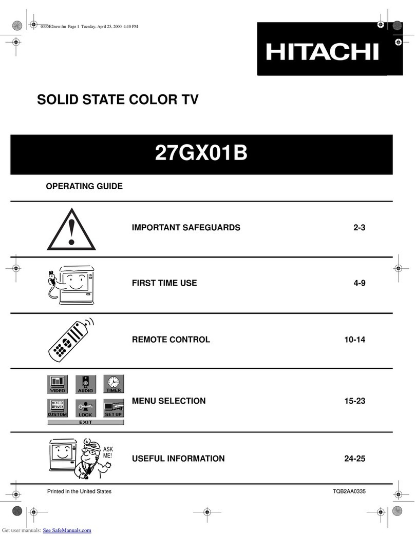
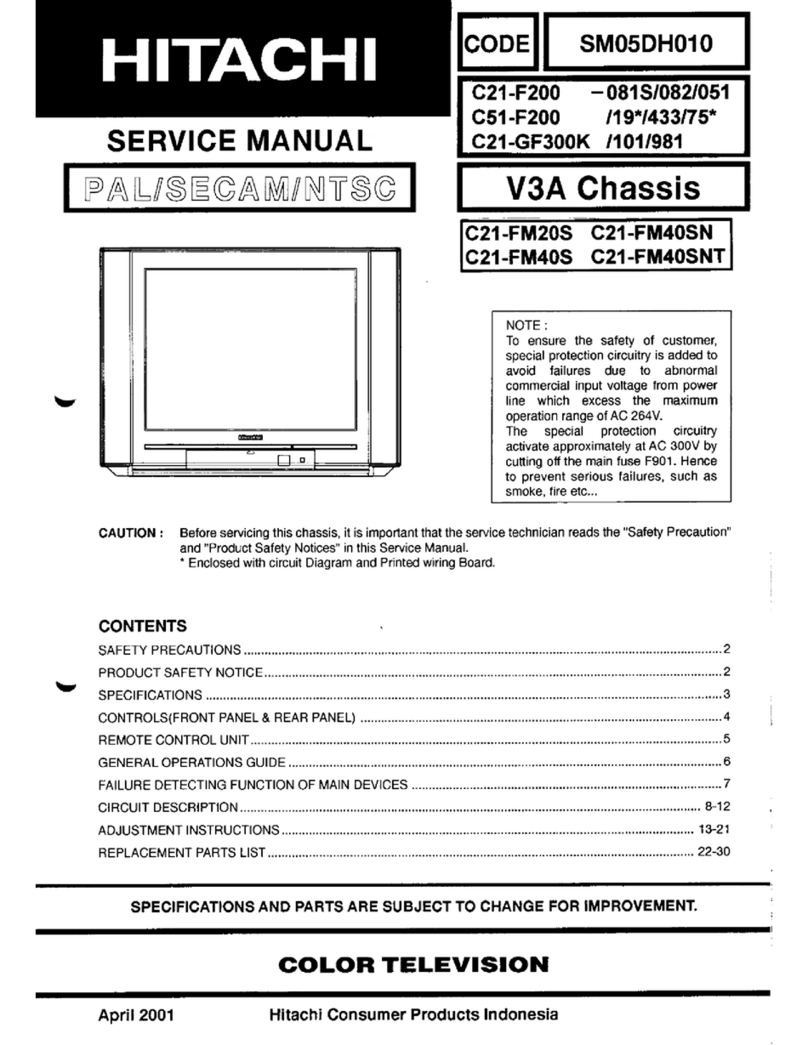
Hitachi CMT2979 User manual

C
ns
(
CAUTION:
June
1996
7
SERVICE
MANUAL
SE:
FORE
ALUULASLIA,
BEA
RUS
Be
Ke
RS
LAER
AT,
Before
servicing
this
chassis,
it
is
important
that
the
service
technician
reads
the
“Safety
IAM
EL
IT
BARREL
GH
Precaution”
and
“Product
Safety
Notices”
in
this
Service
Manual.
HR
AK
AO
TUG
BE
occ
ceseeneresessessseseserennens
4
Ay
EA
A
Ee
EE
RTI
cece
ecessesssseesenssvssens
4
PAE
sseslenadesstontearuhiteasonbaveehinihwhiausel
eae
AE
AUTRE
STA
AGE
cocccsscesccsseessesvcsvessesseesescssesessenteess
TT
ean
res
a
eas
elas
date
nae
eat
abies
JOO1
SPIT
BETA
.scessessesssossessosssssesisvcnessosssasavseseves
P2015
ROU
Be
ae
Bisse
tus
feteca
yeescehievcacesansebavedends
PLE
AAS
ccccvethecsolindaekisedadiaatian
cutee
SRE
EE
HRW
VAIS
oes
ssesss
estes
sssssonesssenssssossssvessenses
Ae
HR
Sait
scrnonosant
asoatbarnvedtere
tararaanineirie:
COLOR
TELEVISION
CONTENTS
SAFELY
PREGAUTIONS
si
dussssrivensestssruccarssiaeouaass
2
PRODUCT.
SAFELY
NOTICES
scccassscsssnivveinnnrsratsnaize
2
Se
ECIFICATIOINS
-saiceta
tat
stessay
sfetaze
eeaeacantavavtnaneinoeds
6
CONTROLS
2c
tivcasteiats
sadn
paclineienternnnitaanniiee
7
REMOTE
CONTROL
UNIT.
:csssnsssoniscssutvaressousssarivenrts
8
ODI
PIN
DESCRIPTIONS
ssssscnstnttcsssitasasiate
sonasndisieens
9
IZOLAIN-DESCRIPTIONS
issicsiscnsniaperniecnasieneieess
10
PLP
SADJUS
[MENT
cs.cpieariiaicdunnnannacnn
1]
VC.OU-ADJUSTMENT
ssssvessenttnss
ittiaiatisxtenadcdeeisaiies
12
AGC
ADJUSTMENT
cccssicscocsocneussistessansssisanianessenaes
13
HORIZONTAL
CENTER
POSITION
ADJUSTMENT....13
VERTICAL
AMPLITUDE
ADJUSTMENT
....ssssseesees
14
ADJUSTMENT:
POINTS
sisssicssesssssorsatisessinncrsessnssonsiee
14
WIRING
DIAGRAM
cis
sscssssnstsaspanecssntmanataiosusnansensdenvs
15
WAVEFORMS
sissdeseitovosiiesiataotuanaiaaiiesed
corks
16
BASIC
CIRCUIT
DIAGRAM
.....sessesesseeees
18,19,21,22
PRINTED:WIRING
BOARD
cisssastssniasesissisevceaveenienss
19
REPLACEMENT
PARTS
LIST
-csiesssssnscsreanaeess
23-36
HITACHI
CONSUMER
PRODUCTS
(S)
cee
eccrine
ON
IZ
[¥s||_No.
o046c-E
|
192S,
041,
051,
981,
0815S,
751
as
spe
RAG
a
HRS
NE
Oh
ore
ce
aH,
Bie
elec
ait
vie
ahs
CMT2979
ee
TECHNICAL
CAUTIONS
SAFETY
PRECAUTIONS
WARNING:
Since
the
chassis
of
this
receiver
is
connected
to
one
side
of
the
Mains
Supply
during
operation,
service
should
not
be
attempted
by
anyone
unfamiliar
with
the
precautions
necessary
when
working
on
this
type
of
equipment.
The
folfowing
precautions
should
be
observed.
1.
Do
not
install,
remove,
or
handle
the
picture
tube
in
any
manner
unless
shatter-proof
goggles
are
worn.
People
not
so
equipped
should
be
kept
away
while
picture
tubes
are
handled.
Keep
picture
tube
away
from
the
body
while
handing.
.
When
replacing
chassis
in
the
cabinet,
all
the
protective
devices
are
put
back
in
place,
such
as;
barriers,
non-
metallic
knobs,
adjustment
and
compartment
cover
or
shields,
isolation
resistors-capacitors,
etc..
3.
When
service
is
required,
observe
the
original
lead
dress,
Extra
care
should
be
taken
to
assure
correct
lead
dress
in
the
high
voltage
circuitry
area.
.
Always
use
the
manufacturer's
replacement
component.
Especially
critical
components
as
indicated
on
the
circuit
diagram
should
not
be
replaced
by
other
makes.
Furthermore
where.a
short
circuit
has
occurred,
replace
those
components
that
indicate
evidence
of
overheating.
5,
Before
returning
a
serviced
receiver
to
the
customer,
the
service
technician
must
thoroughtly
test
the
unit
to
be
certain
that
it
is
completely
safe
to
operate
without
danger
of
electrical
shock,
and
be
sure
that
no
protective
device
built
into
the
instrument
by
the
manufacturer
has
became
defective,
or
inadvertenly
defeated
during
servicing.
Therefore,
the
following
checks
are
recommended
for
the
continued
protection
of
the
customers
and
service
technicians,
INSULATION
Insulation
resistance
between
the
mains
poles
and
any
accessible
metal
parts
should
not
be
less
than
7MQ
at
500V
DC.
Also,
no
flashover
or
breakdown
should
occur
during
the
dielectric
strength
test,
to
apply
4KV
AC
for
one
minute
between
the
mains
poles
and
any
accessible
metal
parts.
bo
>
X-RADIATION
TUBES:
Tie
primary
source
of
X
radiation
in
this
receiver
is
the
picture
tube.
The
tube
utilized
in
this
chassis
is
specially
constructed
to
limit
X
radiation,
For
continued
X
radiation
protection,
the
replacement
tube
must
be
the
same
type
as
the
original,
HITACHI
approved
type.
High
Voltage
This
receiver
is
provided
with
a
hold
down
circuit
for
clearly
indicating
that
voltage
has
increased
in
excess
of
a
predetermined
value,
Comply
with
al!
notes
described
in
this
Service
Manual
regarding
this
hold
down
circuit
when
servicing,
so
that
this
hold
down
circuit
is
operated
correctly.
Serviceman
Warning
With
minimum
Black
Level
and
Picture,
the
operating
high
voltage
in
this
receiver
is
lower
than
31.0K.
In
case
any
component
having
influence
on
the
high
voltage
is
replaced,
confirm
that
high
voltage
with
minimum
Brightness
and
contrast
is
lower
than
33.0kV.
To
measure
H.
V.
use
a
high
impedance
H.
V.,
meter.
Connect
(-)
to
chassis
earth
and
(+)
to
the
CRT
anode
.
button.
(See
the
following
connection
diagram).
NOTE:
Turn
the
power
switch
off
without
fail
before
the
connection
to
the
Anode
button
is
made,
CRT
ANODE
HIGH
IMPEDANCE
H.V,
METER
CHASSIS
GROUND
PRODUCT
SAFETY
NOTICE
Many
electrical
and
mechanica!
parts
in
HITACHI
television
receiver
have
special
safety
related
characteristics.
These
characteristics
are
often
not
evident
from
visual
inspection
nor
can
be
protection
afforded
by
them
necessarily
be
obtained
by
using
replacement
components
rated
for
higher
vol
tage,
wattage,
etc.
Replacement
parts
which
have
these
specia!
safety
characteristics
are
identified
in
this
Service
Manual.
Electrical
components
having
such
features
are
identified
by
marking
with
a
A
mark
in
the
schematics
and
on
the
replacement
parts
list
in
this
Service
Manual.
The
use
of
a
substitute
replacement.
component.
which
does
not
have
the
same
safety
characteristics
as
the
HITACHI
recommended
replacement
one
shown
in
the
parts
list
in
this
Service
Manual,
may
create
electrical
shock,
fire,
X
radiation,
or
other
hazards.
Product
Safety
is
continuously
under
review
and
new
instrictions
are
issued
from
time
to
time.
For
the
latest
information,
al’
ays
consult
the
current
HITACHT
Service
Manual.
A
subscription
to,
or
additional
copies
of,
HITACHI
Service
Manual
may
be
obtained
at
a
nomina!
charge
from
your
HITACHI
sales
offices,
.
D4
iJ
Rosset.
CMT2979
TECHNICAL
CAUTIONS
High
voltage
limiter
circuit
operation
check
1,
Connect
the
high
voltage
voltmeter
between
the CPT
anode
(anode
cap)
and GND
(CPT
grounding
Jead).
2,
Receive
the
broadcast
signal
and
set
the
brightness
and
contrast
VRs
to
max.
Set
the
beam
current
to
1.5mA+10%..
(After
cut-off
adjustment)
3,
Set
the
AC
input
voltage
to
220-43V,
4,
Check
that
the
constant
high
voltage
is
28,0
+1.0kV
at
this
time.
5,
Turn
the
switch
of
the
set
to
off
and
connect
the
jig
shown
in
Fig.3
at
both ends
of
R956
as
shown
in
Fig.
1.
6.
With
the
brightness
and
contrast
VRs
left
as
set
in
item
2
and
with
the
AC
input
voltage
stabilized
at
220V,
turn
the
picture
disappears
with
a
high
voltage
of
32.5kV
or
less.
7.
Turn
the
switch
of
the
set
to
off
immediately
after
the
check
is
completed.
8.
Remove
the
adjust
jigs
and
high
voltage
voltmeter,
NOTE
:
When
connecting
disconnecting
the
high
voltage
volt-
meter
to
from
the
anode
cap,
be
sure
to
turn
the
switch
of
the
set
off and
do
it
after
the
residual
high
voltage
is
discharged
to
the
chassis
because
the
high
voltage
may
remain
at
the
anode
cap.
CPT
Anode
CPT
Earth
Wire
Fig.
2
D.C
Voltage
Divide
15K
Q
5OKQ-B
Digital
Voltmeter
Fig.
3
CMT2979
|
AXRELHMNSH
fea:
AXED,
RAR
RESS
UR
EA)
—
Sn
EL
AGE
He,
TA
AY
A
A
SS
HY
YL
fie
OT
Uo
Hl
AY
ESL
Tes
AP
RANA,
ARB
aE
EEL
ar.
SERB
AMEE
PSUR
BG
SEH,
1
BA,
UREA
mt,
aL
PERE
SMR
Et,
78
HRP
ARMA
RABE,
GRE
MICE
BFE
APRA
ABA
2
ERR
AR
RE
RM,
SAM
PHE
@,
WAR,
EERHHRH,
NERF
aS,
A,
PAS,
th
MYER,
3.
FMR
ZH,
TE
OR
AY
a
Fe
J
EE DA
BB
op
ts
EH
il
Ly,
Ze
Tif
TE
HB
5
[2
ELF,
4.
Bie,
i
eR
AME
OTe
eA
TROL
TE.
SCR
CE
EEL
al
RENO
OLR,
Bea eae
LOL
PH
ay
ie
A
{kA
AV,
SER
AA
RI,
Ala
Fl
iL
FAI
AY
LE
AB
ts
BEE
PACA,
5.
PBR
AV
ALLA
EH,
MB
A
WAC
ML
tt
UA
RAE
E
SEE
Be
HE
PBC
ALF,
cE
BAY
fae,
HA
Shae
A
AL
A
A)
SARTRE,
PRE
EE
bok
MAR,
FF
Em,
MBA
ERT
UPS
Tie,
DRAM
CNR,
HBB
FEL
UR
EL
Ne
AE
iT AY
fk
Be)
a
JR
NY
ZT]
AY
HBB
AS
AT
F796
BE
CH
EE
Dit
S00
1K
He
UY),
EL,
HL
RH
A
A
AA
sth
Oe
ce
ANSP
ZB]
I
ESF
AR
AYR
iE
(1)
Tak
JS
Hit
Se
HR
BEY,
AN
Ye
AE
TA
Bey
Be
lt
Be
ohh
BF
WMA.
X
He
TRE:
AVAL
PAX,
ERA
KGADAE
Br
aR
LLG
BY
BAM
AN
Met,
XH
ED,
YT
RESET
EXEL,
BORER
EM,
i
we
St
FATA
A
S
AV
en
alk
RPL
UL
ASA
—
TT
PBI
HB,
YY
AE
Se
AN
BAY
aC
at
BE
ETA
EMR
SA,
TES
AR DR AB AE AB
BP
AB
Aa
A
a
7a
TE AR
te,
sR
il
AE
TD
TE
SARE,
#4
A
AMES
3B
ULE
Bi
68
A
SD
TY
FEEZLOKVUE
IN.
FERTSAUIM
RN
BYE
AS,
—
ce
ACE
Se
EAT
LL
BER
OL
P
AY
AS,
A
ft
AMR
TF
33.
0kV.
iis
(Fs
ML
RT,
OR
C-
)
BEBE
He
BEM,
S
(+
)
RECRT
(
RHA
)
PAAR
GH,
AMAR
CHV.)
,
(BaF
MARA)
.
ie:
4
REPRE
AAA
GAD
A,
—
ee
AE
TARA,
CRT
5B
th
AXGlmRELHEREM
ACL
MASUR
AA
RRS
HY
fe
TERE.
DCA
Che
TE
HE
Ee
LEER
A
DR,
Ti
EL
BU
(6
(oF
Be
LF
BO
OK
A
At
SRAM,
HR
ey
Be
a
IEA
RP
ERE.
RAE
So
Ee
Bis
Shee
(
BAAR
St
8
EF)
AA
he
a
EAE
AY
LED,
AER
AK
fe
F
AL
AY
OT
SL
A
A
Fe
EB
a
AM
ANULAE,
BRBe
aN
Fk
AP
HA
HE,
UNAS
AB
BE
FI
AS
AB
EAL
A
HITACHI
THE
Ae
BB
GFL
MF
Ud
ERR
HE
AY
LER
AUL
EI,
BEAT
AB
SS
EG,
K,
Xt
BeSe
eB
HITACHIXG
tillan
REA
DHE,
A
BRAS.
Ute
NRA
ES
a
HITACHIM@EF
it,
BY
HITACHIG)
AMRIT
RTH
“AWMBFH
,
AWA
DSA.
RALMEBSMH
Fey
EDR
Gs
oa
A
Pe
1,
JURA
ER
AECPTIAR
(
PARE
)
AIGND
(CPTAYBEHLER
)
ZIAD.
2,
I
-SEROGH
Has,
LRA
MTL
BEAVVRs
(
RIAA
RAS
)
TE
K,
EH
TRA LIA
A
1.SmMA+10%
(
AE
ZS
fa)
CMT2979
3.
#EACHEL
AS
SA
FA
A
922033,
4,
VERY,
Be
ATtE
ce
ey
EH
B28 041
OKY,
5.
FORE
HKKE,
ARUN
KA
PETE
LAR
AR
AYR956
AY
6.
ASAT
EA
AMT
EL
REVRs,
ACH
Tit
Ae
A
FB,
FB
IPR
PRE
AY
220VIR
OL
PA
SOKO.
Fy
25 FE BA aS
DL
tee
SR
ete,
ERAS
WY
Hrt32.5kV,
7,
FeFESCHEIR,
WILE,
Ee
8.
AUP
RA
Fel
ARE
TP
He:
SRA
HERS
AR
PI,
BIG
ARU
HE
FH
I
AL
SG
BF
FE
HEE
I
HMB
se
8
Zia,
ATRL.
AA
SLEXMRE
AL,
DURA
ABE
ii
MAINE
Ril
BaAR
9564
CPT
$i
A
2
15KQ
SOK
Q-B
BRERA
BB
3
wis
RAK
CMT2979
:
|
CMT2979
SPECIFICATIONS
1
CONTROLS
5-H
7
:
P
i
i
a
625-lines
ah
eae
Antenna
input
75
1
COAXIAL
IEC
TYPE
(
ANS
)
Tene
751:
A68AEG25X
Pan
,
NTSC5O
Color
picture
tube
;
ced:
Fs
Reception
system
525-lines
M/NTSC
SE
pe
Niet
Others
:
AG8KSA30X/AG8AEG25X
gob
AL
NTSC3,58-5.5/6,0/6.5
Speaker
JOomax2
7
NTSC4,43-5.5/6,0/6.5
PAL
60
Sound
output
7Wx2
[
081S
:;
AC
200~240V
50/60Hz
041
=:
AC
200/220V.
=
S0Hz
751
=:
AC
240V
50Hz
Power
supply
191
:
A
127V
50/60Hz
(Usable
Range:
100V~280V)
Others
:
AC
110~240V
50/60Hz
(Usable
Range:
100V~280V)
CCIR_
:
E2~12,
E21~69,
S01~3,
$1~10,
$11~20,
$21~41
OIRT.
:
Ri~12,
R21~69
(re
re
JAPAN
:
J1~12,
J13~62
Frequency
range
U.S.A.
:
US2~13,
J~W,
US14~69
Power
consumption
ee
:
anes
eM)
44MHz~863MHz
Hong
Kong,
U.K.
:
UK21~69
Weight
(kg)
40
eee
Te
2
Dimensions
China
:
C1~12,
C13~57
WxHXD
(em)
67.9X56.6X48.4
POWER
ON/OFF
SWITCH
BFK
POWER
STANDBY
INDICATOR
A/S
IT
TIMER
INDICATOR
3
|
aemtagaRty
FE
i
FRSC
REMOTE
CONTROL
RECEIVER
S|
ides
Healy
2p
g
|
INPUT
3
INPUT
TERMINAL
Specifications
are
subject
to
change
without
notice
to
improve
performance.
RRS
TSE
AIMECHD
ij
Sth:
A68KSA30X/A68AEG25X
.
fonhculi
025i
B.G/V/D.K/H
PAL
f
-
|
|
HEADPHONE
JACK
NISD
jth
ORK)
7x2
ee
tab
I
3k
5254
M/NTSC
081S:
39200
~
240
50/60FIz
INPUT
SELECT
NTSC3.58~5,5/6.0/6.5
041:
3Ei#,200/220V
SOHz
8
|
fi
A
tet
NTSC4.43-5.5/6.0/6.5
751:
38Hi240V
SOHz
PAL60
191:
48#£127V.
50/60Hz
(ii
JASE
EE:
100V
~
280V)
HUB:
BEHE110
~
240V
50/60Hz
{ii
FALE
EE|:100V
~
280V)
VOLUME
UP/DOWN
9
|
EHS
/
Me
;
PROGRAMME
UP/DOWN
tst—~<CtstCS~™S
:
|
10
|
Ari
ARIAL
TERMINAL
CCIR
:E2~12,
E21~69,
Sol~3
|
MARE
041:
87
(ECW
13570)
“
ae
,
S1~10,
S11~20,
S21~41
Je(lb:
40K,
Sp
-—
Be
iP)
ewe
wattle
OIRT
:R1~12,
R21
~69
Le
ie
KET
en
BS
ar
re
AV
IN/OUT
TERMINALS
4426
~
86336%
=|
SIRT:
US2~13,
J-W,
USI4~69
|
gi
pest
(BLK)
67.9%
56.6%
48.4
12
|
AV
Si)
A$
LL
a
fii,
JS:
UK21~
69
ae
HpiR):
Cl~12,
C13
~$7
(58%
ih
x
HE)
KR
S
EAT
LA
RI,
MR
ATE,
'
(MT2979
:
_owrz979
|
REMOTE
CONTROL
UNIT
CMT2979
(EAH
L
ISH
E
)
POWER
ON/OFF
PIN
DESCRIPTIONS
OF
[001
(M37221M6-065SP)
1)
igsr/®
|
9
ad
mic
PIN
NO.
;
DESCRIPTION
mp
OE
i
A]
;
;
3
Al
ws
|
al
This
is
the
horizontal
synchronous
signal
input
pin
for
On-screen
display.
r
FEL
Ee
ill
,
in
a
:
ee
ee
a
put
This
is
the
vertical
synchornous
signal
input
pin
for
On-screen
display,
{
|
2
|
INPUT
SELECTION
:
mae
lea
——-
~
POWER
Ay
be
A
EHR
3
TV/S/VIDEO
Output
Selection
of
“TV”
or
“S-VIDEO
in”
or
“VIDEO
in”
signal,
H:
TV
M:
S-VIDEO
L:
VIDEO
REGALL
TVVIDEO
5
tae
SELECTOR
:
ee
Bright
Output
Output
of
the
different
DC
levels
to
control
each
function.
Bs
eure
i
[4
|
g
EROGRAINE
DOWN
7
Output
|
e.g,
COLOR
UP/DOWN,
BRIGHT
UP/DOWN
etc...
a
@
@!
—
|
ee
ee
7)
WEI
_
|
in
utpu
©
a
THEE
_
a
thy
ah
!
;
f
7 .
GAME
|
9
|
4.5
tow
|
Output
|
Contro!
Output
for
SAW
fiter,
L:
4.5tMhz,
H:
Other
EK
R/C
Remote
con.
serial
data
input
from
R/C
receiving
unit
(X0O1)
@
(8)
10
cH
Ve
Oren
aa
1]
Power
Output
Power
on/off
contol.
H:
On,
L:
Stand
by
S
(¥)
TV/TEXT
(Fig
JIF-081S
45
PX-981
1
)
12
Output
for
front
control
matrix
to
control
vol.,
programme.
y
ee
cy
13
Return]
Input
Return
of
front
control
matrix
|
SURROUND
(not
operation
even
if
it
is
pressed).
—
:
a
p
.
(1)
(2%)
Ll
|
spe
(ARYL
AONE)
aa
Return
of
front
control
matrix.
a
as
15
Return3
Input
Return
of
front
control
matrix,
e
4
El
16
Scanl
Output
Output
for
front
contro!
matrix
to
control
vol.,
programme.
RE
in
MUTE
NOISE
REDUCTION
15
|
ai
ysizpe
sae
area
Beep
Output
Beep
sound
output,
L:
Off,
Beep:
irin
50%
Duty
Cycle
4
MHZ
Clock
In
4
MHZ
Clock
Out
_
2.
—_
=
lela)
Jel
16)
rite
2
af
aN
=
[15]
18
ae
23
S-DET
Input
To
identify
the
voltage
of
S-VIDEO
signal.
MENU
Sync-ldent
Input
A/D
terminal
served
to
detect
the
present
of
H
sync
signal.
y
25
Reset
Input
Resets
1004
initiated
by
Power
(Pin
11)
z
Dee
en
eee
oe
iM
Output
|
Selects
the
sound
system
4.5MHZ
5.5MHZ
6.0MHZ
6,5MHZ
[17]
|
v
VIR
OPERATING
REVS
BG/DK
Output
MoH
H
L
L
|
21)
REHLGINA
GNF
IOUS)
BG.DK
H
L
H
L
CH
I/CH
Il
a
Input
Color
identification
of
PAL
DECAM
or
NTSC
Sess
AFC
Input
AFS
voltage
input.
After
A/D
conversion,
this
pin
also
serve
to
detect
the
present
of
RF
signal
Dimmer
Input
A/D
terminal
served
to
detect
the
present
of
Q004
SW
Output
|
NC
SDAI
In/Out
|
IC
data
select
50/60
Force
|
Output
|
Ident
by
pin
2
and
controls
output
from
this
pin.
L:
60HZ,
H:
50HZ
34
SCLI
lIC
clock
select
35
ON/OFF
Mute
Output
Mute
control
output
36
S-Low
SVIDEO
contro!
output
37
SDA2
In/Out
IIC
data
select
{for
EEPROM)
38
SCL2
Output
|
IIC
clock
select
(for
EEPROM)
OSD-Bik
Output
On-Screen-Display
blankig
output
|
Output
|
Blue
output
for
On-Screen-Display
Output
Green
output
for
On-Screen-Display
Output
Red
output
for
On-Screen-Display
39
a
—
>
ro
|
Vv
|
0B1S
&
:
OTHERS
PX-981
ONLY
i
CMT2979
CMT2979
PIN
DESCRIPTION
FOR
1201
-
TDA
8362
P.
|.
F.
Carrier
Filter
Adjustment
(P.
|.
F.
i232)
pan
cape
rt
NO
ARTS
RE
EAE
AM
INST
me
fel
>
Wir
COym~)
OV
Slo}
Tr
Decoupling
digital
supply
Ground
10
Positive
supply
(8V)
Ground
Decoupling
filter
tuning
Internal
CVBS
input
GENERATOR
>
FP=38,
SMHz
opqop
mz
802
}
BS
|
4.3
SIGNAL
LEVEL:
~10~QdBm
DESCRIPTION
F
: 7
rks/Waveform
Audio
deemphasis
and
+/~
mod.
switch
|
Audio
output
ol
nonvolume
controlled
and
fave
lo
be
bullered.
:
Preparations
for
Adjustment
Adjustment
Procedure
IFcemodulator
tuned
circuit
SAC
BAN
MEE
oF
SSH
AMER
NAY
=
(1)
|
Apply
the
following
signal
across
IF
(1)
|
Adjust
L202
until
a
“Fast
rate
of
IF-demodulator
tuned
circuit
out
and
GND
of
tuner,
charge”
is
seen
on
voltmeter.
Video
identification
output
~
N.C.
‘
Then
adjust
L202
to
obtain
reading
on
Sound
IF in
plus
volume
control
i
veltmeter
as
below.
—
>
:
VIDEO
SIGNAL
External
audio
intput
-
N.C.
GENERATOR
Video
output
ie
FP
SIGNAL
y
Sars
Derived
from
internal
RF
video
output
(Pin
7)
and
supplied
to
the
synchronization,
luminance
and
chrominance
processing
(level
=
2Vpk-pk)
by
selection.
Peaking
control
input
15
External
CVBS
input
Derived
from
external
video
source
and
supplied
to
the
synchronization,
luminance
and
chrominance
processing
f
(level
=
LVpkpk)
by
selection.
SIGNAL
LEVEL:
PHILIPS
PATERN
0
FP
16
Chroma
+
A/V
switch
input
DC
voltage
control
the
selection
of
internal/external
CVBS
(Pin
13
or
15)
and
audio,
: .
,
ie.
<0.5V
:
Internal
signals
(2)
|
Connect
the
oscilloscope
to
the
pin
44)
V
=
4:3+0.2V
>7.5V
:
External
signals
of
1201
7
Brightness
contro!
input
18
B-output
19
G-output
20
R-output
21
RGB-insertion
and
blanking
input
2
R-input
for
insertion
NO
ine)
w
G-input
for
insertion
B-input
for
insertion
Contrast
control
input
Saturation
cou.
ee
tg
ee
ee
27
Hue
contro!
input
Color
decoder
selection
between
NTSC
or
PAL/SECAM.
ie,
O~5Y
:
NTSC
decoder
activated
>6V_
:
PAL/SECAM
decoder
applied
no
>
nN
won
nh
ao
B-Y
input
signal
29
R-Y
input
signal
R-Y
output
signal
BY
output
signal
SECAM
Reference/Communication
Loop
filter
burst
phase
detector
3,58
MHz
X-tal
connection
4,43
MHz
X-tal
connection
Start
horizontal
oscillator
Start
supply
pin.
If
the
start
voltage
is
below
5.8V,
the
horizontal
output
will
be
disabled,
(Normal
—
7,2V~8.8V)
w
Oo
GW}
Wi
Go
WERT
w
>
w
an
Wiw
Wiw
oymi
o
Horizontal
output
Flyback
input/sandcastle
output
%-2
loop
filter
ive}
>
Oo
-1
loop
filter
41
Vertical
feedback
input
Vertical
ramp
generator
Generates
a
linear
sawtooth
output
for
the
vertical
output
stage.
43
Vertical
drive
output
This
pin
is
the
current
output
of
the
vertical
preamplifier
and
drives
the
vertical
deflection
stage.
The
amplifier
has
a
feedback
output,
Pin
41,
in
order
to
sense
the
current
in
the
vertical
D.Y.
AFC
output
5
IF-input
IF
input
from
Tuner
and
Saw
Filter,
>
>
=>
a
hr
> ~
Tuner
AGC
output
Voltage
to
change
the
Tuner
gain
when
RF
input
signal
amplitude
becoems
too
strong.
AGC
decoupling
capacitor
The
Tuner
AGC
control
takes
over
when
IF
input
reaches
a
certain
input
level,
the
take
over
point
is
adjusted
af
this
point,
=
fee)
Tuner
take-over
adjustment
Audio
output
Decoupling
sound
demodulator
Decoupling
bandgap
supply
on
ise)
=
-10-
-li-
CMT2979
VCO
Adjusment
(For
0818,
751,
051
&
PX-981
Only)
VCO
ia
Preparations
for
Adjustment
(1)
Connect
frequency
counter
between
19
pin
of
[E01
and
GND
via
Amp
(Gain=4-dB)
19
pin
of
IEQ1
(2)
|
Put
E0113)
pin
to
GND
via
1000,
(3)
Apply
9V
to
EL14.
(Another
Method)
(1)
Connect
spectrumanalyzer
between
19
pin
of
IEOL
and
GND.
Spectru.
19
pin
of
IEO1
Analyzer.
(2)
Put
SG
(38.9MHz+5kHz
without
modulation}
signal
to
GND.
And
increase
output
level
till
spectrum
analyzer
detect
that
level.
19
pin
of
IEO1
fe
(3)
Connects
IEO1
pin
3
to
GND
via
1000,
SG
(38.9MHz+5kHz)
(4)
Apply
9V
to
LE14,
Adjustment
Procedure
Remarks/Waveform
Amp.
should
be
amplify
only
38.9MHz,
To
prevent
VCO
frequency
drift,
make
heat
run
more
than
10
minutes
before
adjustment.
Adjust
LEQ2
as
frequency
counter
shows
38.9MHz+300kHz
Adjust
LEO2
til
the
frequency
difference
between
VCO
and
SG
signal
within
+
300kHz.
~12-
Fe
Sal
mea
Ree
LALA
Ye
te
an
gee
NT
LD
RET
ESET
ewes
neeund
ee
AGC
ADJUSTMENT
(AGC
i)
Preparations
for
Adjustment
.
Adjustment
Procedure
Received
following
channel
and
strength.
(1)
With
the
signai
received,
apply
heat
run
for
more
than
two
minutes
to
avoid
the
influence
of
circuit
temperature
drift.
(2)
Connect
the
voltmeter
of
at
least
1002
internal
impedance
to
the
AGC
terminal
of
the
tuner.
(1)
CHANNEL
STRENGTH
:
-47dBm
CMT2979
Remarks/Waveform
CCIR
5
Adjust
R222
until
the
following
voltage
is
reached,
V1+0,5v+0,2v)
V1:
the
voltage
without
signal
HORIZONTAL
CENTER
POSITION
ADJUSTMENT
(7k-F
(teva)
Preparations
for
Adjustment
Receive
the
circle
pattern
signal.
(2)
Set
the
brightness
and
contrast
VRs
to
maximum.
Adjustment
Procedure
Remarks/Waveform
Picture
information
amount
The
amount
of
information
means
the
amount
of
the
transmitted
picture
that
can
be
displayed
on
the
CPT
screen.
It
is
necessary
to
increase
this
amount
of
information
as
much
as
possible
and
also
decrease
the
lack
of
raster
as
far
as
possible.
Turn
R702
(H.
Phase)
and
adjust
so
that size
scales
on
the
left
and
right
are
equal.
within
1.5~2
(recommended
scale)
Size
scale
-13-
CMT2979
CMT2979
VERTICAL
AMPLITUDE
ADJUSTMENT
(2H
(2
515%)
WIRING
DIAGRAM
Preparations
for
Adjustment
Adjustment
Procedure
Remarks/Waveform
tin
(
ie
3
4
re
cea
ee
Start
adjustment
5
minutes
or
more
Select
V.
CENT
select
chip
"U”,
“N"
ad
y
after
the
power
switch
is
turned
on.
and
“D"
so
that
the
center
of
the
|
picture
is
closest
to
the
geometrical
Receive
the
PAL
circle
pattern
signal.
center
of
the
CPT.
Set
the
brightness
and
contrast
VRs
Adjust
R620
to
obtain
the
following
to
maximum.
conditions.
|
Place
the
set
facing
north
or
south,
Receive
the
NTSC.circle
pattern
signal
and
check
that
the
picture
is
the
same
as
that
when
a
PAL
signal
is
received.
Top
shrinked,
Standard
Top
expanded,
,
bottom
expanded
condition
bottom
shrinked
|
Picture
condition
sao
i
i}
()
,
|
oe
|
Adjustment
Center
of
inner
and
outer
circles
Center
of
inner
circle
|
method
Picture
bottom
Inner
circle
Center
of
inner
and
outer
circles
|
ADJUSTMENT
POINT
(8822
(iz)
s
ae
Elo
WE
|
MAKE
2
:
MO
TALL
wi
|
Me
LEO2
L202
TO
AVOID
TUNER
|
=31;
TOUCHING
BETWE
ps
}
oo,
12
HATS
7
f
E108
18
me
:
j
DIRECTION
SHOWN
R222
f
FOCUS
ADJ.
SCREEN
ADJ.
2%
Be
ih
T/TEXT
P.W.B.
(AFA¥F081S-5PX-981)
T/Text
P.W.B.
(for
081S,
PX-981
only)
wad,
-15-
CMT2979
WAVEFORMS
(6)
1201
(5
pin
1001
PIN_NO.
VOLTAGE
PIN_NO.
Liz}
is
|
19
|
a
fai]
a
2
[5.2
[52
|
ac
[0
|
p23 123
97
@)
1201
@
201
©
pin
@
pin
34
36
et
38
fag
ao
fa
fae
i.
Sy
Drotince
a
a
[ee
po2rt
of oy
oy
ak
av)
ard
wae
1002
aim
ioe,
a)
ee
eo
[vourace
“oot
oo
|
sep
se
[oper]
1004
2.
-
p
1,
3Vp-p
[enna
|
33)
lEO1
Pi
NO.
i
Beart
C7[
se
sToln]
elusive]
a]
VOLTAGE
15.7]
74
|
meets
oe
ees
is
a
a
ee
ee
ee
ae
ee
FIN
NO.
pane
Patent
eee}
IEO2
Tenn.
[1]
7.3
[vourace
a
so
a3
1EO3
K—
1H
—>|
k-———
1H
——_
1201
@9
pin
de
Parana
aa
a
14
15
6
17
4.1
4
4.1
4.
(6)
1901
@:V-DY
TOLTAGE
Pa
hee
s+
rt
tet
L
PIN
NO,
Saw
ieTee
ra
—
2
fT
—m
3.
|
32
|
33]
[34
|
=a
re
|
37
|
38
|
39
|
28
C25
[26
[25]
2]
aa.
FIN
NO.
|
|
41
|
ae
a
rae
ana
|
volTAGE
2
|
|
of
2
1402
:
PIN
AO,
2
[vourase
ae
an
ai
[ae
[ae
ae
|
eo
as
[as
peo se]
op
ae
fae
ae
[ae
1301
3{[
4]
5]
Pfs
eae)
13
rn
ee
ee
ee
20
Lvourace
2
of
a9
62
ae
[a2
[5.2
|
49
15.2
15.2
52
52
[49
[39
[ao Tas
|
oo
13s
VOLTAGE
4.9
T
ts
51Vp-p
650Vp—p
Vp-p
Le
me
|
;
A
rears
cera
kK-14uS4
kK
1H
——>}
51
id
Tewno
i
ita]
sa,
a]
se,
e[ 7]
8] e]
plu
2]
[vorace
ae
oee
o
oye
ae
eo
pepe
e
|
(801
<
Pewno
a
se
sp
et
a
@)
1201
BD
pin
®
Q708
Collector
Q)
120162
pin
PAL
ih
vourace
ere]
128
Ae
1601
1901
pnno
[i
[2]
aja[s]«
pwno,[itels]
«|
s[s]7]
s]
2]
VOLTAGE
0
12
26.8
1.3
26.2
VOLTAGE
300
1,6
2
‘a
p
:
Vp-p
Fo.
25¥p-p
ace
o
[
te
[eee]
Oo
fo
|
13
|
eee
|
Poppa
re
poy
o
pee
aa)
1902 19C3
pune]
1]
2]s[a]
se)
z[3
VOLTAGE
|e]
5
[OL
OPTS]
e
[vous
|
eo
[3
ii
ya
oes
[eT
ey
€)
Poser
[ae]
Tose
[aye]
]
=
|
kK—
1H
—
ER
EEL
(8
CREE:
RE
Toss_[
[eT]
[oesa
[a
Te]
|
3
vouace
|
5.2
Os
|
ea
os
(8)
1201)
pin
Q2
1201
@
»j
|
in
SECAM
a
[erase]
]
[ems
[a
Te
TF]
A
[vournee
|
hoo
Fo
[vourrce
[oo
[
oJ
orp
wot
oO]
[ono
[Te]
8
E
qua
Ja]
el.)
i
ra
VOLTAGE
730
[
0]
ir
9901
8
=.
2).
|go30
|
a|{
cle
a
6
OV
1,
Vp-p
es
ie
250]
0
[230
[
VourAGe
|
“74
|
10.0]
Bs
|
_
OVp-p
v
pee
ee
Poss
ee
a
a
|
VOLTAGE
[770.0
[55.0
|
70.0
voltage
[0
|
700
[
0
|
ine
[12.0
[120
|
BL
ee]
a
a
7
A
5
a
[worrase[0.5-[
oo
VOLTAGE
k-——-
1V
———>
te—
1¥
—>|
[esse
|
es
[
cl
|
[oss
Te
[oT
=]
36a
5
7.0-|
20]
35.0
[voutase
[~a8"[
0
|
a8
|
vOUAGE
|
55
[50
|
50]
i
volTaGe
[
7.8
[0
[
4.9
-~
16-
17
:
a
2
Joa
utaet
te
tia
trope
iene
Breytsurea
ge
SA
eT
ATOM
Taree
weeny
antes
seins
secrete
Ateceiites
teat
Stee
aotet
htt
teen
east
Rear
Pepe
agate
ran
ameter
ett
AINE
NAME
OY
ATARI
NES
TENORS
MMAR
S.
aR
EEE
AMES
ey
9
A
terasmmntnan
ey
AM
RW
WE
MSR
oe
tn
ng
airecrianeat
SS
SEPT
AOE
asa
ea
a
ease
eRe
TET
18
{AINO
186-Xd
8
S180
HO4)
WVYOVIG
LINDHIO
DISVE
LXALIISL
SISSVHD
vs
CNMT2979
REAR
{ouTl
£393
7
A
XN
©
FRONT
tins)
FRONT
AV
P.W.
B.
R320
paper
Boe
By
Ip
C312
109K
F
ESF
HES
BSt
ast
s0/16
oe
i
bj
e313
2ycais
A307
109
1/sw0
PSaiaao
A309
t/D
)
150
A310
Ss
a/en
190
*
soo/10
}*
30/48
9314
HzS9Cc3
R544
470
C103
9.904
R502
4so
A570
100
azo:
2SC13906
R204
R264
27
R216
100
051.
-983
~751 ONLY
(R244)
tnd
by
oO
_
LS
SOl5
<3
io
so
io"
a
3
8
43
Q
R222
R219a
=
oo.4
10K-B
4.
7K
g
ba
~~“
“xz
on.
3s
BR
32
R734
40
z
Ray
=
aa
g|
|
R702
sOR-B
2
rere
oO
5
H.
PHASE.
a
&
DHO
1
HZ5:
ae:
2
o
a
tat
+
2se34ia
rE
=
<
e
S
x
x
x
S
EY
a
oy
x
n>
a
o.
3
ra
Rose
3316
R421
100
1/8"
R422
100
s/BW
A904
g9G2
2804413
90012
188270
pois
SUH-SBVC3F
STAND~BY
SCOOFSPT
STS
ays
Ross
cs
1K
eo
Nu
z
'
A140
40K
ROBO
iSK
470/316
Y
C439
470736
=
% =
R441
AK
A
ET
=
40/36
5
:
4
cais a404
az
C905
uao2
©-<
oe
0.4
2803433
~f
100710
£402
z
Raos
R404
(}
4
i
2.2
i/an
s7au
vy
A434
3.5K
PRODUCT
SAFETY
NOTE
:
Components
marked
with
a
A\
and
shaded
have
special
characteristics
important
to
safety.
TO
COME
PL
a.8.
Before
replacing
any
of
these
components,
read
carefully
the
PRODUCT
SAFETY NOTICE
of
this
Service
Manuai.
Don’
t
degrade
the
safety
of
the
receiver
through
improper
servicing.
AEAR
-
-
(xIN3)
7
£301
—N,
oe
CPT
P.W.B.
2
=.
7X
ASS3
199%
i/aa
v
a
Lu
v
ae
ge
Sih
a
RSGD
ASSS
100K
1/<W
©
©
WA
470
:
cas:
wf
ase
27P
AB
15891
Tpa6i03
8
Bx. ex,
Bab
Sop
a8
13a8
T/T:
2
ow.
ge
ape
oo}
FS
R303
100
i/8W
2
ee
en
De ee
&
i
ee
eel
eT
‘
{|
2
1
SS
PS
ET
eee
oe
Eres
8
5
aa
Eanes
Ee
eee
2
He
Bes
Dae
ey
&
(lc
eee
ees
eee
et
x
aa
ey
oe
Peemeens
See
2)
}¥|
|x
S
Se
DOC
Ge
ee
EE
7
al
oF
ee
eee
Bae
ee
ae)
aes
Trloh
fe
a
aes
eee
en
Ree
ell]
=
BSc
ee
=
Par
eae
oe
:
casa
15e
{ise
T/T)
is
25
Rage
C397
180
|
S50P
(120°
T/T]
wo
EN
se
rye
aa
27K
A387
cs60
2200p
A833
470K
1/2
TO
vM
P.
4.8.
TG
TELETEXT
©.
4.5.
4
G3
ow
4
"
#8
8
ra
se
z
~
£2
»
By,
o
~
=
<
=
4
H302
|
ot
a
n
Go
>
e
3.
2
Et)
© ©
©
©
&
S&S
O
iP
vee
o
n
7
FROM
FST
CIACUIT DIAGRAM
2/3
*Ag21
(580)
rm
°
ry
re
»
fe
rv
w
pcos
Hzssc3
ASIGBS
18K
{044,954
ONLY]
T/T
LS
echalal
2sv
>
430¥
>
.
PULSED
-
DRIVE)
GND
mats
¢
av
vs
vwvwvy
sv
DHO2
cv7aa
Hzsaci
eg
4000P
ON/OFF
>
s0/60
>
Vv.
GAMP
>
——H.
SAIVE
GND
>
HEATER)
200v
>
TO
CIACUIT
DIAGRAM
2/3
H.BLK
>
:
V.FB
>
Bev
>
i—
{
aAcL
>
————<
A.
SUT
>
L.ouT
>
4.SLO")
Ir
>
seli
>
SDAI
>
AF.
IN
>
sv
>
TO
CIACUIT
DIAGRAM
3/3
sv
>
{
4.5H
>
AF2IN
>
cES7
100/10
470/40
SIGNAL
CURRENT
core
ao
COMPOSITE
Yte
VIBES
SIGNAL
Coi4
0-04
cos3
2803433
NS
4901
CY
2803413
fh
{ON/OFF
orhaorf—
Rosa
=
ae
aoa?
TL
cgas
AUDIO
SIGNAL
:
rt
ROIS
22K
+
a
:
=
a
|
pescak:
=
AQHA
40K
Sea
ae
yd
=a
CMT2979
BASIC
CIRCUIT
DIAGRAM
1/3
!
‘
‘
7
:,
;
soo3
©
Since
this
is
a
basic
circuit
diagram,
the
value
of
the
parts
is
subject
to
be
altered
for
improvement.
:
e
Ali
DC
voltage
to
be
measured
with
a
tester
(100k
/V).
Valtage
taken
on
a
complex
color
bar
signal
including
a
standard
color
bar
signal.
my
CMT2979
MCL
437
FEX
1.6t
1/@
GRAIN
oy
metres
20
OS
Dre
gn
ona
RE
items
Se
at
LUA
CCE
AUN
EAM
meee
tn
aetna
nates
Geese
te
ae
.
:
<--
44
QQ
'O2E
=
A
—->
i
a&
w@
the
tw
Loe]
w
wo
~~
r
,
qa
ey)
pm]
-—--—>
‘96
<O/S)
X
=
396.
00
mm
>
@9
JAN
N
DIRECTION
—C
CMT2979-
CMT2979
BASIC
CIRCUIT
DIAGRAM
2/3
‘
'
'
“6
i)
os
Fr
all
t
Pula
!
seu
is
et
ia
01
fs
pea,
1
1h
ae
°
i
4
Red-a3te
'
ran
es
ei
|
'
2210
ac
Ava
ADE
’
ara
rranat
Se
i
oe
i
.
fuer
w.
>
premnsanye
:
rae
ree
:
t—
4a)
.
a
oz
T?
kd
x
pea
ron
g
cw
8/400
——
;
it
a
24/99
pure
ey
ae
oN
° "
nn
—-:
.
a
ty
ue
wea
HOt
498
alan
ans
ree
|
ae)
930
RE
—
{4
asraasg
meth
ane
faa
FI
RS
nese
wT
as
R945
RIS
onge
avart
ee
atte
i
Drains
.
9
i)
20K
™
hee
af
Fo
rite
iw
ato
(
|
94
1908
ape
)
gece
d
.
(eaoat
+f
y
an
¥e
iy
pniseas
pss
Pei
Wie
4
——+}
if
Ns
asasz
MI
re
et
case
povs
Ra
,
Paes
CO
Ges)
2200P/900
HES
70
“ss
ve
7
on
cede
$c4190L
ease
ee
Myon
—i
9)
oe
a
3a0R/309
OBIT
oe
0.017409
iy
icnya:
I
vara
un
Sy
7
Nise
as
aH
Cy
ome
EUS
oot
By,
vey
L
|
eserora
f
‘|
palo
>
ama
a
mss.
&
Rasy
sx
Hy
E
ay:
OKO
eet
ne
ae
8B
1048:
=
i
Po
tly
z
=
Be
ara
see
a)
x
cao9
ta
i
Yi
34087800
a
i
ura
uate
100716
——-{
«
}
é
ree)
eee
ey
opt
pai
seer
A
Fu-o1a8
cosy
Rat
a
—
i
|
axons
$
har
i
cas)
$nN2e
[ener
{49/89
ory
Py
Pars
is
)
ifs
0
la
a
a)
,
Lome.
ween.
A902
pars
oss
(9)
(
aacszi3a
CP
479
sa8ery
eH
NE
:
.
Age
bio
CWO
pay
4.4%.
491
Gog
8
s800P/im
asaiz
E
—
cece
|
ee
a!
ME
ATER,
T
ma
ase
R060
Reso
aie
a
:
tas
BOK
2.9K
19%
8790/99
I/ne
en
.
CHa
{commeumeene
SCLALA)
4708/2%
aa
036s
L
ary
ae.
ee
a
—enrrnnnefonaemncwenend
He
BLK)
Aw
0.15
a
=
$
oid
case
pase
ae)
Ra
109/38
109
ar)
*
—
{
v.96
)
0939
estrone
on
ris
Migiety
nc
ome
TL
>
aa
i/ae
ry
——
(lao
ifn
9
ee
SLi
i
olan
we
lel
ein
See
SiN
SlalS
eee
oe
wee
amin
de aa
Sew
eae
ba
ain
aan
eas
ans
ons
Pyoury
ies
Hrsi203
|
100K
4/40
Ra
10%
ah
cre
Ries
BH
oz
1m
ATG
D
O42
traszea
axvew
[an
eaa778
aK
D107
DARIN
Sy
cra8
45/689
5
Dr4p
p73
T
HEEL
sa%e70
$
r
|}
———-
>}
ooo
>
|
nea
=|
«
ANCOE
)
ot
woe
400%
a
i
aargaly
«recut
)
|*
4
B
a)
ile
merens
sare)
da
tas
mk
Tan
e
b
ra)
rh
ies
a
ons
Rho
ane
Al
AGao
AND
ee
=
AN
aa
Cha9
to
—_
96387433
Py
pieve
iil)
3)
“
ie
2099
ures
|
te
"
in?
co
rer
beset
pals
eve
7
bet
ee
ae
Wen
ans
,
2.0ae7eto
ae
Ene
———
=
1
we
anne
3
biec
RUcs
A
een
TH
S48
109997500
40%
“
P/Y
!
(erie
nent
:
rer)
rhea
one
a
ene
|
orem
nade
be
Faroyee
Taso,
Ta.
8
652
seareae
i
othe
te
cen,
es
t
ewrasis
OX
Owe
acre
©
eae
Ria
Nag
ie
cree
ene
an
ae
S30P/d00
T2200
/809
whoa
fae
Nias
ca
pcninaiins
WAN
A738
0.
OK
ven
te
ws
rE:
5
21
CMT2979
x€02
5.
74MHz
SIF“Aa/NICAM
0.94
br
Grol
2961900
REOG
¢
céO4
ae
0.99
g
EOL
Ko2s34
REOB
480
RE15
27K
E
Seen
CEi4
0.91
CMT2979
BASIC
CIRCUIT
DIAGRAM
3/3
Loa
vco
(£04
hi
|
LAi00
Cei2
CEia
bg
0.05
il
Len
OF06
AGS
2841390
Si
c/o
09
(C)
O€oG
H28443
i
E40
ee
crs)
Ett
DEO7
we
6.8
840se
xE07
(it
ate
RESS
cea?
ean
iH
400P
—
{00P
hese
aak
J
;
I
wise
Tar/is
SFS5
sate
CETBA
G4
{oS
MODE
ONLI
t—-——
pt
Ses
pp
Se
es
DEO)
E08
AHO
12
LaLog
7
DE10
wages
f°
DEOR
Mzssc3
CE33
Wm
Ce34
10/46
+
*
40/36
oFoR
eseaaia
LAY
REQ
820
NICAK*ONLY
aeoa
ascaasa
\_AJ
RE2a
HONO“ONLY
100
4
saa
jew
100740
KEQ?
'
e
i
KEO8
(
t
"
NeZ6
Of
Ce34
820
22
RS0-458
c/p
GFOH
OTC1
4488
RFS
A6K
RF
38
400
E39
AESG
40/16
18k
Ceaa
10/48
KEGB
|
z
S
u
v
be
ee
ey
TO
CIACUIT
OLAGAAM
1/3
a
CMT2979
REPLACEMENT
PARTS
LIST
a»
PRODUCT
SAFETY
NOTE:
Components
marked
with
a
A\
have
special
characteristics
important
to
safety.
4,
Before
replacing
any
of
these
components,
read
carefully
the
PRODUCT
SAFETY
NOTICE
of
this
Service
Manual.
Don't
degrade
the
safety
of
the
receiver
through
improper
servicing,
-
Sate
SRR
EL
ETRE
coe
Pie
mene
en
ds
ABBREVIATIONS
Capacitors
.......6.
CD:
Ceramic
Disk,
PF:
Polyester
Film,
EL:
Electrolytic,
PP:
Polypropylene,
PR:
Paper,
TA:
Tantalum,
TM:
Trimer.
ReSIStOrS
....scecverees
CF:
Carbon
film,
WW:
Wire
Wound,
FR:
Fuse
Resistor,
MG:
Metal
Glazed,
CAs
a
aad
Ne
ER
WON
VR:
Variable
Resistor,
CC:
Carbon
Composition,
MF:
Metal
Oxide
Film.
Semiconductors
.....
TR:
Transistor,
Di:
Diode,
ZD:
Zener
Diode,
VA:
Varistor,
TH:
Thermistor.
SYMBOL
|
NO.
|
PART
NO.
DESCRIPTION
C112
O800003R
|
EL
IMF
SOV
O880009R
|
PF
O.0IMF
+10%
50V
(FOR
0818,
PX-981)
C201
0890087R
|
CD
LO00PF
+10%
SOV
¢204
O880016R
|
PF
0.IMF
+10%
50V
(205
0800003R
|
EL
IMF
S0V
C206
0800057R
|
EL
220MF
10V
C208
O8800]6R
|
PF
O.IMF
+10%
50V
0880009R
|
PF
O.0IMF
+10%
50V
(FOR
051,
0818,
751,
PX-981)
DESCRIPTION
CHAS
MTG
METAL
A4Y
R
CHAS
MTG
METAL
A4Y
L
IR
HOLDER
A4Y
LED
HOLDER
A3
G9
EE
HOLDER
(S)
3*12
B-T
SCREW
WITH
WASHER
4X16
B
TAPPING
SCREW
V
HEAT
SINK
M3LXU
HEAT
SINK
S2
(H)
A1LOOP-H14
PART
NO.
NA02493
NA02501
NJO0921
3874636
3816162
4319361
4519512
3446864
MA00141
SYMBOL
NO.
3442421
|
HEAT
SINK
C212
O880009R
|
PF
0.01MF
+10%
50V
FI
3445843
|
POWER
HEAT
SINK
AIPN C213
0800273R
|
EL
0.22MF
50V
3446473
|
HEAT
SINK
H30
P10
C215
0880016R
|
PF
O.IMF
+10%
50V
i
PF
O.01MF
+10%
SOV
CD
22PF
+5%
SOV
PF
0,047MF
+10%
SOV
C220
0880009R
(250
0890065R
(302
0880014R
HEAT
SINK
H50
P10
BS
POWER
HEAT
SINK
GO
$4
CPT
QUT
HEAT
SINK
3446475
3445841
MA00661
4520883
|
3*12
SCREW
WITH
WASHER
304
0880016R
|
PF
0.IMF
+10%
SOV
4
4520881
|
M3X8
SCREW
WITH
WASHER
0305
0880016R
|
PF
O.IMF
+10%
50V
:
8821114
|
NUT,
3
C306
0880016R
|
PF
O.IMF
+10%
50V
‘
4519504
|
3*8
B
TAPPING
SCREW
C310
0800015R
|
EL
1OMF
16V
2
1ME2004
|
PVC
SHIELD
PLATE
0312
0800015R
|
EL
1OMF
16V
e
3746071
|
IEC
CORD
HOLDER
(313
0800048R
|
EL
1OOMF
10V
2
JKO2411
|
MAIN
PWB
C315
O800015R
|
EL
1OMF
16V
3
0880012R
|
PF
0.022MF
+10%
SOV
C316
0800015R
|
EL
1OMF
16V
.
0800003R
|
EL
IMF
SOV
(317
0800015R
|
EL
1OMF
16V
a
EL
10MF
16V
EL
1OMF
16V
EL
10MF
16V
EL
1OMF
16V
EL
1OMF
16V
EL
10MF
16V
EL
LOMF
16V
EL
1OMF
16V
EL
1OMF
16V
EL
10MF
16V
(330
0800015R
(341
0800015R
(342
0800015R
(343
0800015R
0344
0800015R
0345
0800015R
C346
0800015R
(347
0800015R
(348
0800015R
(349
0800015
EL
100MF
10V
PF
O.IMF
+10%
50V
CD
O.0015MF
+10%
SOV
CD
120PF
5%
50V
CD
120PF
+5%
SOV
CD
120PF
+5%
50V
EL
470MF
10V
PF
O.0IMF
+10%
SOV
CD
100PF
+5%
SOV
PF
O.01IMF
+10%
50V
0800048R
0880016R
0890089R
0890075R
0890075R
0890075R
0800352R
0880009R
0890074R
0880009R
0800003R
|
EL
IMF
SOV
(350
0800353R
;
EL
470MF
16V
0800003R
|
EL
IMF
50V
(351
0800032R
|
EL
33MF
16V
0800003R
|
EL
IMF
50V
(352
0800353R
|
EL
470MF
16V
0800003R
|
EL
IMF
SOV
(353
0800015R
|
EL
LOMF
16V
0800003R
|
EL
IMF
SOV
(354
Q800015R
|
EL
LOMF
16V
0800015R
|
EL
10MF
16V
(355
0880009R
|
PF
O.OJMF
+10%
SOV
PF
O.O1MF
+10%
SOV
EL
10MF
L6V
CD
20PF
50V
PF
O.O1MF
+10%
SOV
EL
1OMF
16V
FL
1OMF
16V
C356
0880009R
(361
0800015R
0248667R
0880009R
0800015R
0800015R
CD
100PF
5%
50V
PF
O.0IMF
+10%
SOV
EL
4.7MF
50V
EL
100MF
10V
PF
O.0IMF
+10%
SOV
EL
LOMF
16V
0890074R
0880009R
0800012R
0800048R
0880009R
0800015R
309%
CMT2979
@MT2979
|
HmRELES:
CPRAPAMENAA
SHANE,
Be
Me
ela
HED
ATA
DBE
AREF
UPR
“il
ee
EATER
HB,
DU
eS
8
4
Ti
A
LL
ESE,
PRODUCT
SAFETY
NOTE:
Components
marked
with
a
/\
have
special
characteristics
important
to
safety.
Before
replacing
any
of
these
components,
read
carefully
the
PRODUCT
SAFETY
NOTICE
of
this
Service
Manual.
Od
=
Don't
degrade
the
safety
of
the
receiver
through
improper
servicing.
No.
|
PART
NO.
DESCRIPTION
NO.
|
PART
NO,
DESCRIPTION
|
NO.
[PART
KO.
DESCRIPTION
NO,
[PART
NO.
DESCRIPTION
| 7
¢737
|
0288442
|
EL
2200MF
+20%
35V
c954
|
0251703
|
EL
390MF
+20%
160v
C384
|
O800353R
|
EL
47OMF
16V
C512
|
0800326R
|
EL
LO0MF
16
C738
|
0243510R
|
CD
S60PF
+10%
S00V
0284478R
|
EL
1OMF
+20%
100V
385
|
0800015R
|
EL
LMF
16V
C513
|
0880016R
|
PF
O.IME
10%
Sov
fag
«GEM
ae
Meleinn
|
eoM
C386
|
O890068R
|
CD
39PF
+5%
SOV
C514
|
0880018R
|
PF
0.22MF
++10%
SOV
ye
Ocaate
Ea
aor
EC
TQOME
ai
¢387
|
0890076R
|
CD
150PF
+10%
50V
(515
|
O880016R
|
PF
O.IMF
+10%
SOV
me“
qenapin
eer
ine
ity
fsa
en
pomp
sib
aiby
¢387
|
0890075R
|
CD
120PF
+10%
50V
C516
|
0284634R
|
EL
4.7ME
SOV
ia
Nonna
myenaye
|
PEOTIME
IG
(FOR
O81S,
PX-981
ONLY)
C516A
|
0284634R
|
EL
4.7MF
50V
(BP)
(FOR
O41,
051
ONLY)
sag
Nidsonnrnsl
Go
ease
ce
oessorn
Key
saiPe
te
NN
ean
|
(wR
OBIS,
PX-981
ONLY)
C520
|
0890116R
|
CD
1SPF
+5%
50V
A
C782
|
O249491F
|
CD
470PF
+10%
2.5KV
0g0005R
|
EL
2.2NF
SOV
cal
|
0890069R
|
CD
47PF
+5%
SOV
0525
|
0284646R
|
EL
22ME
10V
man
(agnor
nt
ced
earey
naosser
(EL
iia
1a)
c402
|
og80009R
|
PF
0,01MF
10%
Sov
531
|
0800353R
|
EL
470MF
16V
oe
Panu
eae
ona
ERNE
Cai
c4os
|
O800015R
|
EL
1OMF
16V
0552
|
0880016R
|
PE
O.IME
+10%
50V
sage
anna
ean
MOR
VESTN
SI
te
ait
OME
ae
aa
et
cra
gee
C787
|
0800326R
|
EL
100MF
16V
0244202F
‘|
CD
470RF
=-10%
2KV
(NOT
FOR
041)
TMF
10%
~
c791
|
o890068R
|
CD
39PF
=:5%
Sov
O244211F
|
CD
LOOOPF
++10%
2KV
(FOR
041)
cai!
—
|
og00326R
|
EL
LOOMF
16V
C602
|
OBB0009R
|
PF
O.OIMF
+10%
50V
cy
anit
Vssase
ben
epee
on
ratoneay
ec
eane
ee
C412
|
0800326R
|
EL
LOOMF
16V
C610
|
GB80015R
|
PF
O.06@MF
=10%
SOV
:
eel
tape
Gy
pe
TaRIOLIR
|
BE
ATR
Sap
c413
|
ogoo3z6
|
EL
100MF
16V
C611
|
0244501R
|
cD
1000PF
=10%
S0oV
Fonte
oan
oa
io
inonais.
Feaaeee
ee
C415
|
o8g0016R
|
PF
O.IMF
+10%
SOV
Cél1A
|
0243509R
|
CD
470PF
10%
SooV
caso
|
oagoasae
|
cp
Ispr
5%
say
C971
|
0243509R
|
CD
470°
+
10%
500V
C416
O880016R
|
PF
O.IMF
+10%
50V
C612
0800052R
|
EL
1OOMF
35V
C85
ogsooss
|
cD
29PE
“+50
OV
0980
ogooagr
|
EL
1OONF
10V
_
C417
|
0800041R
|
EL
47MF
16V
C613
|
O800015R
|
EL
10MF
16V
TORUS
oe
On
aa
enema
Eee
Wy
Cais
|
0g00353R
|
EL
470MF
16V
C614
|
O880011R
|
PF
O.OLSMF
+10%
SOV
sue.
|
Wiis
ce
tee
ay
ae
RNR
Pe
nite
sth
C419
|
og00353R
|
EL
470MF
16V
C615
|
O880009R
|
PF
O.OIMF
+10%
50V
prea
(nuance
ben
itee
Ste
on
a
Coa
alate
Vee
ink
ly
C421
—
|
ogg0009R
|
PF
O.01MF
+10%
Sov
C616
|
0880017R
|
PF
OLSMF
+10%
SOV
TOR
THiS
HEH
OAS
remo
ne
C422
|
oggo069R
|
CD
47PF
+5%
50V
C617
|
0800368N
|
EL
2200MF
25V
-
iNest
sais
leavin
‘eaRtUEL
Gel
751;
AC
C23
|
OBROUOSR
|
PF
O.OLMF
10%
SOv
C618
|
OBOOOIZR
|
EL
4.7MF
SOV
t}
\
40855
|
0880018R
|
PF
O.22MF
+10%
50V
ceo2
|
o8go009R
|
PF
O.0IMF
+10%
50V
ca2s
|
0284623R
|
EL
IME
50V
C619
|
0279693R
|
PF
O.IMF
10%
100y
pee
(Kioaara
CIM
ORE
on
Ok
is
EP
Raat
ton:
ARIE
WEES
See
ear
ere
c860
|
o24agsar
|
cD
2200PF
2kV
+10%
2KV
CE03
|
OB80009R
|
PF
O.OINF
+10%
50V
coe,
Olga
eae
Fe
ae
rote
ea
eget
A
C901
|
0262773
|
PF
O.1MF
+20%
250V
(FOR
041,
751)
(FOR
051,
081S,
751,
PX-981)
ior.
wl
mannan
ee
aie
Tee
Bere
naan
eta
eeic
A
C901
|
0262774
|
PF
O.22MF
+20%
250V
(NOT
FOR
041)
0880009R
|
PF
O.OLNF
+10%
SOV
:
redcas
F
sean
CEE
GME
A
C902
|
0262773
|
PF
O.IMF
+20%
250V
(FOR
041,
751)
(FOR
051,
0818,
751,
PX-981)
at
pene
:
nid
ia
ee
ee
neue
OTE
Ine
a
A
C903
|
0262773
|
PF
O.JMF
+20%
250
(FOR
O41.
751)
0800001R
|
EL
0.47MF
50V
Sam
ea
a
vee
ee)
MENA
C903
|
0248594F
|
CD
0.01MF
+80%-20%
250V
(FOR
051,
0818,
751,
PX-981)
C432
|
08800048
|
PF
O.OOISMF
10%
Sov
C659
|
OBBO016R
|
PF
O.IMF
10%
50V
ane
eee
at
esucrisie
eal
ere
gate
NPR
le
a
Sea.
|
SuROUlee
FEC
Wine
SIR
be
C903
|
0262773
|
PF
O.IMF
+20%
250V
(FOR
981,
1925)
(FOR
051,
O81S,
751,
PX981)
1
DOI,
Pie
IMF
£10%
a
904
|
0248593F
|
CD
A700PF
+80%-20%
250V
0800277R
|
EL
O.47ME
50V
fae
Wana
Nee
a
Tae
ii
Oa
C906
|
0248594F
|
CD
O.0IMF
+80%-20%
250V
0890076R
|
CD
150PF
+10%
50V
+10%
‘OOIMF
=+10%
50V
(FOR
81S,
P¥-981)
Re
sR
amma
eA
c907
|
0251886
|
EL
330MF
+20%
400V
(NOT
FOR
041)
(FOR
051,
O81,
751,
PX-981)
sha
es
,
751,
Pk-
ame
c907
|
aLooogs
|
EL
330MF
450V
(FOR
041)
08g0009R
|
PF
O.0IME
+10%
SOV
84623R
|
EL
IMF
50V
C703
|
O880005R
|
PF
0.0022MF
10%
S0V
|
C908
|
O800063N
|
EL
220ME
63V
(FOR
051,
O81,
751,
PX-981)
C435
|
o800005R
|
EL
2.2MF
Sov
C705
|
0800334
|
EL
220MF
10V
;
c909
|
o284436R
|
EL
LOOME
35V
0880009R
|
PF
O.0IMF
+10%
SOV
C437
|
0800353R
|
EL
470MF
16V
C710
|
O880016R
|
PF
O.IMF
+10%
Sov
;
3
C910
|
0890087R
|
CD
LO0OPF
++10%
SOV
(FOR
051,
O81S,
751,
PX-981)
C438
|
o880045R
|
PF
O.012MF
+10%
SOV
C711
|
0890087
|
cD
LO0OPF
10%
Sov
cat}
(onan
t
Eom
one
reer
a
agitre
C439
|
O880016R
|
PE
OLMF
+10%
Sov
C715
|
0287850R
|
CD
68PF
+5%
SO0V
acho
:
C912
|
0244213
|
CD
1S00PF
-+10%
2KV
(FOR
051,
751)
(FOR
051,
0818,
751,
PX-981)
C440
|
0800048R
|
EL
100ME
1oV
6716
|
0243507R
|
CD
330PE
+10%
500V
:
,
;
C912
|
028a202F
|
CD
470PF
+10%
2KV
0880009R
|
PF
O.0IMF
+10%
SOV
c445
|
og0036aNn
|
EL
2200MF
25V
C717
|
0284505R
|
CD
2200PF
10%
500V
digs
-'llcgaeniogn
omar
nape
Te
shi
FOR
O8IS,
751,
PY-981)
c450
|
oggoo09r
|
PF
O.0IME
+10%
SOV
C718
|
0299918F
|
PF
0.022MF
+10%
200V
ae
a
Tso!
PMR
Gatbine
oe
ig:
TIlE
on
C915
|
o880044R
|
PF
O.01MF
+10%
Sov
O880016R
|
PF
O.1MF
10%
SOV
(FOR
O81S,
PX-981)
nr
+10%
+10%
916
|
0243507R
|
CD
330PF
+10%
SOOV
0880009R
|
PF
O.01MF
=+10%
SOV
(FOR
O81S,
P¥-981)
O890116R
|
CD
15PF
+5%
50V
C721
|
O880016R
|
PF
O.1MF
+10%
S0V
fee
C930
|
0800043R
|
EL
47ME
35V
0880016R
|
PF
O.IMF
+10%
SOV
c502
|
ogg0007R
|
PF
0.0047MF
10%
SOV
A
6723
|
0262416
|
PF
0.0039MF
L.8KV
:
|
C931
|
0800326R
|
EL
LO0ME
16V
(FOR
051,
O81S,
PX-981)
C503
|
0880016
|
PE
OLIMF
+10%
50V
A
C725
|
O262801F
|
PF
OSGMF
5%
250V
:
:
C932
|
O800074N
|
EL
470MF
16V
0890061R
|
CD
1OPF
05%
SOV
(504
|
0800015R
|
EL
LOMF
16V
(726
|
0244501R
|
CD
1000PF
+10%
S00V
Blois
<'
|
Goetahore
PEL
Soe
ee
NeatbON
Poet
ELE
Gal
C506
|
O800015R
|
EL
1OMF
16V
A
C727
|
0262429F
|
PF
0.012MF
+5%
1.SKV
See
a
ee
sata
|
nemipae|
Cine
ok
Poe
pore
|
se
nren
cae
C951
|
0244202F
|
cD
470PF
10%
2KV
0800326R
|
EL
1OOMF
16V
(FOR
OBIS,
751,
PX-981)
,
0952
|
0243607R
|
cD
330PF
+10%
S00V
0880016R
|
PF
O.IMF
10%
SOV
510
|
0890087R
|
CD
LOOOPF
+10%
SOV
(729
|
0299720F
|
PF
O.O1L5MF
630V
age
e@aore
eb.
caine
ee
an
(FOR
0815,
751,
Px-98))
e511
|
oggoos7R
|
cD
1000F
+10%
SOV
¢730
|
0259474
|
EL
6.8MF
25V
=
ENS
-—
25
-
CMT2979
“
MT2979
|
HARE
LAES:
PEMA
MICHA
GE
IM
REE,
BH
HLL
DL
TEA
WEARER
ITP
“tli
Re
LAER”
—B,
Dike
AE
RAL
A
ee
HE,
PRODUCT
SAFETY
NOTE:
Components
marked
with
a
/\
have
special
characteristics
important
to
safety.
Before
replacing
any
of
these
components,
read
carefully
the
PRODUCT
SAFETY
NOTICE
of
this
Service
Manual.
Don't
degrade
the
safety
of
the
receiver
through
improper
servicing.
SYMBOL
SYMBOL
NO.
|
PART
NO.
NO.
|
PART
NO.
DESCRIPTION
O880009R
|
PF
O.01MF
+10%
50V
CE65
|
O800041R
|
EL
47MF
16V
(FOR
051,
0815,
PX-981)
2339869M
|
2D
HZSSC3
2344041M
|
DI
1$$254/18S270
(FOR
081S,
751,
PX-981)
CE66
|
O880016R
|
PF
O.1MF
+10%
50V
(FOR
051)
2339869M
|
ZD
HZS9C3
2339491M
|
DI
AMO1Z
200V
(FOR
O81S,
751,
PX-981)
0880041R
|
PF
0.0056MF
+10%
50V
CE66
|
O880016R
|
PF
O.1MF
+10%
SOV
(FOR
081S,
PX-981)
2339869M
|
ZD
HZS9C3
2339869M
|
ZD
HZS9C3
(FOR
O81S,
751,
PX-981)
(FOR
081S,
751,
PX-981)
CE67
|
0880003R
|
PF
O.001MF
+10%
50V
2339491M
|
DI
AMOIZ
200V
2339823M
|
ZD
HZS4-A3
(FOR
051,
0815,
PX-981)
0800015R
|
EL
10MF
16V
(FOR
0818,
751,
PX-981)
(FOR
051,
0818,
PX-981)
2339231M
|
ZD
HZS30-1L
2343901M
|
DI
BB405B
(FOR
051,
0818,
PX-981)
CE26
|
O880009R
|
PF
0.0IMF
+10%
50V
CE68
|
0800041R
|
EL
47MF
16V
(FOR
051,
081S,
PX-981)
2339231M
|
ZD
HZS30-1L
2339869M
|
ZD
HZS9C3
(FOR
051,
081S,
PX-981)
(FOR
081S,
751,
PX-981)
CE69
|
0880062R
|
PF
0.22MF
+10%
50V
2344041M
|
DI
18S254/1$8270
2339869M
|
ZD
HZS9C3
(FOR
051,
081S,
PX-981)
CE27
|
O880009R
|
PF
0.01MF
+10%
50V
(FOR
051,
0818,
PX-981)
2343962M
|
DI
MPGO6G
2339869M
|
ZD
HZS9C3
(FOR
0815,
751,
PX-981)
(FOR
081S,
751,
PX-981)
CE70
|
O8B0016R
|
PF
O.IMF
+10%
50V
2344041M
|
DI
18S254/1$8270
2339869M
|
ZD
HZS9C3
(FOR
O81S,
751,
PX-981)
CE28
|
0800058R
|
EL
220MF
16V
(FOR
08iS,
751,
PX-981)
(FOR
051,
0818,
PX-981)
2348511
|
DI
RS3FS
2339857M
|
ZD
HZS7C1
CE29
|
0880037R
|
PF
0.0033MF
+10%
50V
CE71
|
0800041
|
EL
47MF
L6V
(FOR
052,
0818,
PX-981)
2344041M
|
Di
18S254/188270
2339827M
|
2D
HZS4C1
(FOR
081S,
751,
PX-981)
CE76
|
O880009R
|
PF
O.01MF
+10%
50V
2344071
|
DI
ERC20M-04
2122652M
|
FERRITE
CORE
WITH
LEAD
CE30
|
0890069R
|
CD
47PF
+5%
50V"
(FOR
051,081S,751,PX-981)
ee
2338902M
|
DI
DFMISA4
2693863)
TERMINAL
JPJ1989
(FOR
081S,
751,
PX-981)
CE77
|
0800048R
|
EL
1OOMF
10V
(FOR
051,
081S,
PX-981)
{
&
2339481M
|
DI
ASO1Z
200V
2693851
|
TERMINAL
JXT1043
CE31
—
|
O800005R
|
EL
2.2MF
SOV
(FOR
O81S,
751,
PX-981)
|
CE80
|
O880006R
|
PF
3300PF
+10%
50V
i
2338902M
|
DI
DFMISA4
2673601
|
US
13PIN
JACK
CE32
|
0800002R
|
EL
0.47MF
100V
(FOR
081S,
751,
PX-981)
(FOR
051,081S,
PX-981)
2348511
|
DI
RS3FS
2902267
|
8P
SUB
MINI
PLUG
PIN
CE33
|
O800015R
|
EL
1OMF
16V
(FOR
081S,
751,
PX-981)
CE80
|
0880007R
|
PF
0.0047MF
+10%
SOV
(FOR
751)
2344041M
|
DI
18S254/1$8270
2902264
|
SP
MINI
PLUG
PIN
WITH
BASE
CE34
|
O800015R
|
EL
1OMF
16V
(FOR
081S,
751,
PX-981)
CE82
|
0800326R
|
EL
100MF
16V
2339481M
|
DI
ASOIZ
200V
ee
A
ie
PIN
W/BASE
ZD
H2S1203
ZD
HZS12C1L
Di
ASO1Z
200V
2339889M
2339151M
2339481M
CE35
0800048R
|
EL
100MF
10V
(FOR
051,
081S,
PX-981)
CE36
Q800015R
|
EL
1OMF
16V
(FOR
051,
081S,
PX-981)
CE37
O800015R
|
EL
10MF
16V
(FOR
051,
0818,
PX-981)
(FOR
051,
0815,
751,
PX-981)
CE86
O880016R
|
PF
O.IMF
+10%
50V
(FOR
081S,
PX-981)
CE87
0800048R
|
EL
100MF
10V
2611361
|
SWITCH
2122652M
|
FERRITE
CORE
WITH
LEAD
CE39
O800015R
|
EL
10MF
16V
D001
2344041M
|
DI
18S254/1S8270
2339889M
|
ZD
HZS12C3
2665272
|
4P
PLUG
PIN
W/BASE
(UL)
HAS
CE40
0800048R
|
EL
100MF
10V
D002
2339837M
|
ZD
HZS5C1
2339212M
|
ZD
HZS24-2L
2956783
|
2P
CONNECTOR
WITH
WIRE
(UL3239)
CE4]
O800015R
|
EL
10MF
16V
D003
2339819M
|
2D
HZS3C3
e
2335991M
j
2D
H2T33-02
E80]
EF03941
|
7P
CONNECTOR
W/WIRE
Cecnaet
E802
2661751
|
2P
PLUG
PIN
WITH
BASE
£880
2698673
|
SQE-HPS1401-019690
£880
2953344
|
CRT
SOCKET
(FOR
751
ONLY)
E902
2661753
|
4P
PLUG
PIN
WITH
BASE
E903
2995909
|
25
PROCESSED
WIRE
WITH
AMPIN
A
E904
|
EVOOO01
|
SAA
POWER
CORD
(FOR
751)
A
E904
|
EVO0O71
|;
POWER
CORD
(FOR
051)
A
E904
|
2972581
|
POWER
CORD
(FOR
041)
A
E904
|
2972582
|
POWER
CORD
(HEWTECH)
(FOR
191,
192)
A
E904
|
2972591
|
POWER
CORD
~
(FOR
O81S,
PX-981,
1928,
981)
E906
2729252AR)
FUSE
HOLDER
(TAPE)
2D
HZS12C1L
DI
18$254/188270
DI
AMO1Z
200V
DI
18$254/1$8270
DI
18$254/1$8270
DI
RBV-406M(LF-A)
DI
ASO1Z
200V
DI
ASO1Z
200V
Di
ASO1Z
200V
DI
ASO1Z
200V
DI
ASO12
200V
DI
ASO1Z
200V
2339151M
2344041M
2339491M
2344041M
2344041M
2338314
2339481M
2339481M
2339481M
2339481M
2339481M
2339481M
a
D004
2344041M
|
DI
18$254/1$8270
D005
2344041M
|
DI
18$254/18S270
D006
2344041M
|
DI
18$254/1$S270
D007
2344041M
|
DI
18S254/1$S270
D008
2339839M
|
ZD
HZS5C3
D015
CHOO231A
|
LED
SLH-56VC3F
D016
CH00232
|
LED
SLH-56MC
D031
2344041M
|
DI
18$254/18S270
D101
2339869M
|
ZD
HZS9C3
D102
2339869M
|
ZD
HZS9C3
4,
D201
2344041M
|
DI
18$254/18S270
Lp
D202
2339889M
|
ZD
HZS12C3
CE42
0800015R
|
EL
10MF
16V
CE46
O880009R
|
PF
O.0IMF
+10%
50V
(FOR
051,
0818,
PxX-981)
CE47
0890074R
|
CD
100PF
+5%
50V
(FOR
081S,
PX-981)
CE48
0890074R
|
CD
100PF
+5%
50V
(FOR
051,
0815,
PX-981)
CE49
0880019R
|
PF
O.33MF
+10%
S0V
(FOR
081S,
PX-981)
CE5O
0880048R
|
PF
0.022MF
+10%
50V
(FOR
0818,
PX-981)
CES]
0880016R
|
PF
O.IMF
+10%
SOV
(FOR
0815,
PX-981)
CES2
Q800003R
|
EL
LMF
SOV
(FOR
0815,
PX-981)
CES3
0890082R
|
CD
390PF
10%
SOV
(FOR
051,
0815,
PX-981)
D301
2339869M
|
ZD
HZS9C3
2339482M
|
Di
ASO1 400V
E907
3763752
|
SK
BINDER
200
CES4
0890061R
|
CD
10PF
+0.5%
50V
D302
2339869M
|
ZD
HZS9C3
2339481M
|
DI
ASO1Z
200V
A
F901
|
2720402
|
FUSE
3.15A
(FOR
051,
0818,
PxX-981)
D305
2344041M
|
DI
18S254/1$S270
2339884M
|
2D
H2512B1
FB118
=|
2123468M
|
FERRITE
BEADS
CORE
0.8MH
CE55
0880016R
|
PF
O.IMF
+10%
50V
D306
2344041M
|
Di
188254/1SS270
2339053M
|
ZD
HZS7B3L
FB956A
|
2123462M
|
FERRITE
BEADS
CORE
2.3
MICRO
H
(FOR
051,
0818,
PX-981)
D307
2344041M
|
DI
18$254/18S270
2330843M
|
ZD
HZS6A3
G80!
CJO0071R
|
SPARK
GAP
CE56
0800018R
|
EL
LOMF
SOV
(FOR
051,
0818,
PX-981)
D308
2344041M
|
DI
18S254/1SS270
2338931
|
DI
FMG-G26S
G802
(J00071R
|
SPARK
GAP
0880016R
|
PF
O.IMF
+10%
50V
D309
2339869M
|
ZD
HZS9C3
2338902
|
DI
DFMISA4
G803
CJO0071R
|
SPARK
GAP
D310
2339869M
|
ZD
HZS9C3
2349851
|
DI
FM8-G16L
G90]
CJ00071R
|
SPARK
GAP
(FOR
051,
0818,
PX-981)
EL
LOMF
SOV
(FOR
051,
0818,
PX-981)
CD
220PF
+10%
50V
(FOR
051,
0818,
PX-981)
EL
LOMF
SOV
(FOR
051,
0818,
PX-981)
EL
1OMF
SOV
(FOR
051,
0818,
PX-981)
PF
0.047MF
+10%
SOV
(FOR
‘051,
0818,
PxX-981)
H30)
HP00151
|
Y/C
COMB
FILTER
H302
2902269
|
10P
MINI
PLUG
PIN
WITH
BASE
(FOR
0815,
PX-981)
A
1001
|
CP01882
|
IC
M37221M6-065SP
A
1002
|
CP00822
|
IC
M6M80042P
A
1004
|
2003522R
|
IC
PST572D-2
2004411
|
IC
TDA8362/N3
2339481M
2339481M
2338944
2339481M
2339481M
2344041M
2339481M
DI
ASO1Z
200V
DI
ASO1Z
200V
DI
FML-G12S(F)
DI
ASO1Z
200V
DI
ASO1Z
200V
DI
188254/18S270
DI
ASO12
200V
D311
2339869M
|
ZD
HZS9C3
D403
2339885M
|
ZD
HZS12B2
D404
2339885M
|
ZD
HZS12B2
D405
2344041M
;
DI
188254/18S270
D406
2339481M
|
DI
ASO1Z
200V
D410
2333001M
|
DI
RU2M
D501
2344041M
|
DI
188254/188270
se
CE58
0800018R
0890078R
CE60
0800018R
CEG]
0800018R
CE62
0880053R
0880062R
|
PF
0.22MF
+10%
50V
D502
2344041M
|
DI
18S254/1$8270
Ue
2339022M
|
2D
H2S6B2L
(or
P#2004415
IC
TDA
8362/N5)
(FOR
051,
0818,
PX-981)
D503
2344041M
|
DI
188254/1$8270
2339051M
|
2D
HZS7B1L
A
1301
|
2004652
|
IC
1A8777BN
0880003R
|
PF
0.001MF
+10%
50V
D504
2339835M
|
2D
HZS5B2
2339888M
|
2D
HZS12C2
A
1401
|
2020601
|
IC
MM1053xS
ZD
HZ85C1
CP01831
|
IC
M62420SP
D505
2339869M
|
2D
HZS9C3
2339837M
(FOR
051,
0815,
PxX-981)
~
26
-
OF
us
"
e@MT2979
ims
EC
AEE:
CT
RA
ICH
ULAR
ees
PISA
FM lh
ee
EER
PART
NO.
2004022
SYMBOL
NO.
SYMBOL
NO.
DESCRIPTION
IC
AN7147N
CP02611
|
IC
TDA
4665
2004431
|
IC
TDA8395
2913981
|
IC
AN5521
A
1801
|
CPO1931
|
IC
TDAG103
A
1901
|
2373382
|
IC
STR-S6709
A
1902
|
2004761
|
IC
TLP631
(BL-LF2)
A
1903
|
2003423
|
IC
UPC7893AHF
A
TEQL
|
2004171
|
IC
LA7577
(NOT
FOR
041,
981,
192,
1925)
A
IE02
|
2004971
|
IC
TDA9840
(FOR
081S,
751,
Px-981)
A
IEQ3
|
CPO1601
|
SAA7283ZP
(FOR
051,
O81S,
PX-981)
J401
2672041
|
HEADPHONE
JACK
K201A
|
9371901
|
UNINSULATED
COPPER
WIRE
K292A
|
9371901
|
UNINSULATED
COPPER
WIRE
KCE37
|
9371901
|
UNINSULATED
COPPER
WIRE
L001
2123461M
|
FERRITE
BEADS
CORE
0.8MH
L002
2123461M
|
FERRITE
BEADS
CORE
0.8MH
L101
2123781R
|
PEAKING
COIL
100
MICRO
H
+10%
L202
2146114
|
HIGH
FREQ.
COIL
38.9MHZ
L205
2122932M
|
LAL
AXIAL
COIL
1.5MH
+
10%
L206
2123781R
|
PEAKING
COIL
100
MICRO
H
+10%
ND901
1380
2123109M
|
LAL
AXIAL
COIL
33MH
+
10%
138]
2123104M
|
LAL
AXIAL
COIL
12MH
+
10%
Q001
1381
2123103M
|
LAL
AXIAL
COIL
1OMH
+10%
Q002
(FOR
081S,
PX-981
ONLY)
0003
L401
2123104M
|
LAL
AXIAL
COIL
12MH
+10%
Q004
L405
2123461M
|
FERRITE
BEADS
CORE
0.8MH
Q005
L501
2123102M
|
LAL
AXIAL
COIL
8.2MH
+10%
Q007
L502
2123105M
|
LAL
AXIAL
COIL
15MH
+
10%
0201
L507
2123103M
|
LAL
AXIAL
COIL
10MH
+10%
0202
L508
2122956M
|
LAL
AXIAL
COIL
100
MICRO
H
+10%
0203
L611
2123461M
|
FERRITE
BEADS
CORE
0.8MH
Q204
L701
2124183
|
CHOKE
COIL
Q205
L702
BZ01351
|
LX
LINEARITY
COIL
27UH
0206
L702
2165404
|
LX
LINEARITY
COIL
27H
(FOR
751
ONLY)
|
Q301
L703
2125763R
|
RADIAL
COIL
Q302
L704
BHOO2O6R
|
FIXED
COIL
27
MICRO
H
+10%
L901
2276071
|
LINE
FILTER
30MH
(FOR
751, 041)
L901
2276072
|
LINE
FILTER
15MHZ
(NOT
FOR
041,
751)
L902
2276072
|
LINE
FILTER
15MH
(FOR
751, 041)
L904
2161152
|
FILTER
COIL
L906
2123461M
|
FERRITE
BEADS
CORE
0.8MH
L951
2123462M
|
FERRITE
BEADS
CORE
2.3MH
L952
2123462M
|
FERRITE
BEADS
CORE
2.3MH
L953
2125804N
|
FILTER
COIL
33
MICRO
H
L956
2125804N
|
FILTER
COIL
33
MICRO
H
L957
2123462M
|
FERRITE
BEADS
CORE
2.3MH
L958
2123462M
|
FERRITE
BEADS
CORE
2.3MH
L959
2123462M
|
FERRITE
BEADS
CORE
2.3MH
L960
2123462M
|
FERRITE
BEADS
CORE
2.3MH
L961
2771892
|
FERRITE
BEADS
CORE
(004)
L962
2771892
2771892
2771892
2125804N
FERRITE
BEADS
CORE
(004)
FERRITE
BEADS
CORE
(004)
FERRITE
BEADS
CORE
(004)
FILTER
COIL
33
MICRO
H
~
28+
YA
Seat
Re
HE,
BERR
He
Ee
HL
ELL
AT
TEAR
i,
PASE
Ss
LAB
7B
4
TA
EAE
FHL
LA
PART
NO.
2123462M
2123462M
2123462M
2122925M
2146116
2122253M
2122253M
2146081
2122941M
2774731R
2122253M
2774731R
3446852
2327773M
2327773M
2327773M
2312995
2327773M
2327773M
2320144
2327773M
2326872R
2326872R
2320144
2327773M
2327753M
2327773M
2327753M
2327773M
2327753M
2327773M
2327753M
2327773M
2327773M
2327773M
2327773M
2327753M
2327753M
2326873R
2321351M
2315933
2323522M
2327753M
2327773M
2327773M
2327773M
2123105M
DESCRIPTION
FERRITE
BEADS
CORE
2.3MH
FERRITE
BEADS
CORE
2.3MH
FERRITE
BEADS
CORE
2.3MH
LAL
AXIAL
COIL
0.47MH
+10%
(FOR
051,
0818,
751,
PX-981)
HIGH
FREQ.
COIL
38.9MHZ
(FOR
051,
0818
,751,
PX-981)
LAL
AXIAL
COIL
15MH
+
10%
(FOR
0818,
751,
PX-981)
LAL
AXIAL
COIL
100MH
+10%
(FOR
051,
0818,
751,
PX-981)
LAL
AXIAL
COIL
100MH
+10%
(FOR
0815,
751,
PX-981)
7MM
IF
COIL
(FOR
0818,
751,
PX-981)
LAL
AXIAL
COIL
6.8MH
+
10%
(FOR
051,
0818,
PX-981)
FERRITE
BEAD
CORE
WITH
LEAD
(FOR
051,
0818,
PX-981)
LAL
AXIAL
COIL
100MH
+
10%
FERRITE
BEAD
CORE
LEAD
HEAT
SINK
(NOT
FOR
041,
081S,
751,
PX-981)
TR
2803413
(C/D)
TR
2803413
(C/D)
TR
2803413
(C/D)
PHOTO
TRS,
RPT-38PT3F(L/M)
TR
2803413
(C/D)
TR
2803413
(C/D)
TR
2801906
TR
2803413
(C/D)
TR
DIC114ES
TR
DIC114ES
TR
2801906
(FOR
051,
0818,
751,
PX-981)
TR
2803413
(C/D)
TR
2SA1390
(C/D)
TR
2803413
(C/D)
TR
2SA1390
(C/0)
TR
2803413
(C/D)
TR
2SA1390
(C/D)
TR
2803413
(C/D)
TR
2SA1390
(C/D)
TR
2803413
(C/D)
TR
2803413
(C/D)
TR
2803413
(C/D)
TR
283413
(C/D)
TR
2SA1390
(C/D)
TR
2SA1390
(C/D)
TR
DTC144ES
TR
2SA836/844
D/E
TR
2$B1548A-P/Q
TR
2SD789E
TR
28A1390
(C/D)
TR
2803413
(C/D)
TR
2803413
(C/D)
TR
2803413
(C/D)
aie
pari
4
he
ee
yee
ap
CMT2979
PRODUCT
SAFETY
NOTE:
Components
marked
with
a
A\
have
special
characteristics
important
to
safety.
Before
replacing
any
of
these
components,
read
carefully
the
PRODUCT
SAFETY
NOTICE
of
this
Service
Manual.
A
0708
A
0709
a740
0741
A
0742
0901
0930
0951
0952
0953
0954
0955
0956
0957
~~]
0958
Q959
Q96]
Q962
Q962
QE01
QE02
QE03
QEO4
QEO5
\_f
QE06
R001
R002
R003
R004
R005
R006
R007
R008
ROO8A
_4
R009
R010
R011
R012
R013
ROM4
R015
ROLE
R017
R018
ROL8A
RO19
R020
R021
R022
R023
eal
R024
)
R025
R026
R027
R030
2315451
2326216
2320663M
2321
112M
2323782R
2312174
2321351M
CF00114R
2315933
CFO0114R
231593]
2320665R
2320647M
2320647M
2315933
2320637M
2327753M
2312171
2312171
2320144M
2327773M
2327773M
2320596M
2326872R
2327753M
0700054M
0700055M
0700051M
0700056M
0700041M
0700054M
0700047M
0700054M
0700041M
0700054M
0700054M
0700067M
0700048M
0700058M
0700063M
0700054M
0700027M
0700027M
0700058M
0700054M
0700058M
0700058M
0700049M
0100117M
0700067M
0700063M
0700067M
0700064M
0700027M
0700051M
TR
BU2508AF
TR
2803116
S/T
TR
2SC1213AC
TR
2SA778AK-02
THYRISTOR
03P2M
TR
2802375
(P)
TR
2SA836/844
D/E
TR
2504490-AN(Q,R)
TR
2SB1548A-P/Q
TR
2804490-AN(Q,R)
TR
2SB1548A-P
TR
2SC1213A
(D
R)
TR
2861213
(C/D)
TR
2801213
(C/D)
TR
2SB1548A-P/Q
TR
2SA673
(C/D)
TR
2SA1390
(C/D)
TR
2503852
(NOT
FOR
051,751)
TR
2803852
(FOR
051,751)
TR
2501906
(FOR
051,
0818,
751,
PX-981)
TR
28€3413
(C/D)
(FORO51,
081S,
PX-981)
TR
2863413
(C/D)
(FORO51,
081S,
PX-981)
TR
250458
(C/D)
TR
DTGLI4ES
TR
2SA1390
(C/D)
(FOR
051,
0818,
PxX-981)
CF
I/L6W
10K
OHM
+5%
CF
I/L6W
12K
OHM
+5%
CF
1/16W
5.6K
OHM
+5%
CF
I/L6W
15K
OHM
+5%
CF
W/16W
1K
OHM
+5%
CF
I/16W
10K
OHM
45%
CF
I/L6W
3.3K
OHM
+5%
CF
I/16W
1OK
OHM
+5%
CF
W/16W
1K
OHM:
+5%
CF
WV/1L6W
LOK
OHM
45%
CF
W/16W
10K
OHM
+5%
CF
I/16W
100K
CHM
+5%
CF
I/L6W
3.9K
OHM
+5%
CF
Y16W
22K
OHM
£5%
CF
I/16W
47K
OHM
+5%
CF
I/16W
10K
OHM
+5%
CF
W/16W
100
OHM
+5%
CF
V/16W
100
OHM
5%
CF
W/L6W
22K
OHM
+5%
CF
U/16W
10K
OHM
45%
CF
A/L6W
22K
OHM
+
5%
CF
W/L6W
22K
OHM
+5%
CF
U/LEW
4.7K
OHM
+5%
CF
1/8W
150K
OHM
+5%
CF
I/L6W
100K
OHM
+5%
CF
I/IGW
47K
OHM
45%
CF
U/LEW
LOOK
OHM
+5%
CF
I/L6W
S6K
OKM
+5%
CF
I/16W
100
OHM
+5%
CF
I/L6W
5.6K
OHM
+5%
,~
Don't
degrade
the
safety
of
the
receiver
through
improper
servicing.
ae
7
er,
:
‘
:
SYMBOL
SYMBOL
4
NO.
|
PART
NO.
DESCRIPTION
NO.
|
PART
NO,
DESCRIPTION
R03]
R031
R032
R036
R037
R038
RO40
R04]
R042
R043
RO44
R045
RO46
R047
R048
|
ROSO
ROS1
R052
R053
R054
R054
ROSS
R055
R056
R056
R057
R058
R059
R062
R066
R067
RO70
R071
R072
R073
R074
R076
R080
R081
R082
R083
R084
R085
R086
=
90u.
CF
1/16W
120K
OHM
+5%
CF
1/8W
680K
OHM
+5%
(FOR
0815
ONLY)
CF
I/16W
10K
OHM
+5%
CF
1/16W
10K
OHM
+5%
CF
1/16W
39K
OHM
+5%
CF
1/16W
33K
OHM
+5%
CF
1/8W
100
OHM
+5%
CF
1/8W
100
OHM
+5%
CF
1/16W
330
OHM
+5%
CF
1/16W
47K
OHM
=5%
CF
1/8W
100
OHM
45%
CF
1/8W
100
OHM
+5%
CF
I/16W
3.9K
OHM
+5%
CF
1/16W
3.9K
OHM
+5%
CF
1/16W
1K
OHM
+5%
CF
I/16W
2.2K
OHM
+5%
CF
1/16W
390
OHM
+5%
CF
I/16W
390
OHM
+5%
CF
1/16W
1K
OHM
+5%
CF
I/16W
2.7K
OHM
+5%
(FOR
081S,PX-981)
CF
1/16W
3.3K
OHM
+5%
(NOT
FOR
081S,PX-981)
CF
I/16W
2.7K
OHM
+5%
(FOR
081S,PX-981)
CF
1/L6W
3.3K
OHM
+5%
(NOT
FOR
081S,PX-981)
CF
I/16W
2.7K
OHM
+5%
(FOR
081S,PX-981)
CF
I/LGW
3.3K
OHM
5%
(NOT
FOR
081S,PX-981)
CF
I/L6W
390
OHM
+5%
CF
1/16W
390
OHM
+5%
CF
U/16W
390
OHM
45%
CF
L/L6W
1K
OHM
+5%
CF
1/8W
100
OHM
+5%
CF
1/8W
100
OHM
+:5%
CF
L/L6W
1.5K
OHM
+5%
CF
1/8W
470K
OHM
+5%
CF
1/8W
330K
OHM
+5%
CF
1/8W
150K
OHM
+5%
CF
1/8W
220K
OHM
+5%
CF
L/16W
1K
OHM
+5%
CF
1/16W
15K
OHM
+5%
CF
I/L6W
8.2K
OHM
+5%
CF
L/16W
3.9K
OHM
+5%
(FOR
0815,
PX-981
ONLY)
CF
1/16W
6.8K
OHM
£5%
CF
i/L6W
10K
OHM
+5%
CF
I/L6W
3.3K
OHM
+5%
CF
I/L6W
1.5K
OHM
+5%
CF
I/I6W
1K
OHM
+5%
CF
I/L6W
22K
OHM
+5%
CF
I/16W
22K
OHM
+5%
CF
I/16W
1K
OHM
+5%
0700068M
0100133M
0700054M
0700054M
0700062M
0700061M
0100041M
0100041M
0700034M
0700063M
0100041M
0100041M
0700048M
0700048M
0700041M
0700045M
0700035M
0700035M
0700041M
0700046M
0700047M
0700046M
0700047M
0700046M
0700047M
0700035M
0700035M
0700035M
0700041M
0100041M
0100041M
0700043M
0100129M
0100125M
0100117M
0100121M
0700041M
0700056M
0700053M
0700048M
0700052M
0700054M
0700047M
0700043M
0700041M
0700058M
0700058M
0700041M

This manual suits for next models

10

Other Hitachi TV manuals

Hitachi 65QLEDSM20 User manual

Hitachi

Hitachi 65QLEDSM20 User manual

Hitachi 32HYJ46U User manual

Hitachi

Hitachi 32HYJ46U User manual

Hitachi 32HDL52 - 32" LCD TV User manual

Hitachi

Hitachi 32HDL52 - 32" LCD TV User manual

Hitachi 32HAK4258 User manual

Hitachi

Hitachi 32HAK4258 User manual

Hitachi 40HXT16U User manual

Hitachi

Hitachi 40HXT16U User manual

Hitachi LE42S606 User manual

Hitachi

Hitachi LE42S606 User manual

Hitachi C1714T User manual

Hitachi

Hitachi C1714T User manual

Hitachi ULTRAVISION LE22S314 Assembly instructions

Hitachi

Hitachi ULTRAVISION LE22S314 Assembly instructions

Hitachi C2117T User manual

Hitachi

Hitachi C2117T User manual

Hitachi UltraVision L46S603 User manual

Hitachi

Hitachi UltraVision L46S603 User manual

Hitachi 55VH User manual

Hitachi

Hitachi 55VH User manual

Hitachi 49HK6T74U User manual

Hitachi

Hitachi 49HK6T74U User manual

Hitachi CP2025T User manual

Hitachi

Hitachi CP2025T User manual

Hitachi 22HYD06U User manual

Hitachi

Hitachi 22HYD06U User manual

Hitachi 50PD960DTA Installation instructions

Hitachi

Hitachi 50PD960DTA Installation instructions

Hitachi LC57 User manual

Hitachi

Hitachi LC57 User manual

Hitachi 42PD8900TA User manual

Hitachi

Hitachi 42PD8900TA User manual

Hitachi 35UX80B User manual

Hitachi

Hitachi 35UX80B User manual

Hitachi CST258PC User manual

Hitachi

Hitachi CST258PC User manual

Hitachi C15F27 User manual

Hitachi

Hitachi C15F27 User manual

Hitachi L32HK04U User manual

Hitachi

Hitachi L32HK04U User manual

Hitachi 31GX31B/CY35 User manual

Hitachi

Hitachi 31GX31B/CY35 User manual

Hitachi 15LD2200 User manual

Hitachi

Hitachi 15LD2200 User manual

Hitachi 32CX33B User manual

Hitachi

Hitachi 32CX33B User manual

Popular TV manuals by other brands

Philips FTP2.4A Service manual

Philips

Philips FTP2.4A Service manual

Emerson EWT19S2 Service manual

Emerson

Emerson EWT19S2 Service manual

IKEA UPPLEVA user manual

IKEA

IKEA UPPLEVA user manual

North State TV2GO user guide

North State

North State TV2GO user guide

JVC AV-32H35SAE instructions

JVC

JVC AV-32H35SAE instructions

Samsung PN51E8000 E- E-manual

Samsung

Samsung PN51E8000 E- E-manual

Sony Trinitron KV-AR21M81 Service manual

Sony

Sony Trinitron KV-AR21M81 Service manual

Philips Matchline 46PP910A user manual

Philips

Philips Matchline 46PP910A user manual

Panasonic TX-29AK10F Service manual

Panasonic

Panasonic TX-29AK10F Service manual

Westinghouse DWN40F1Y1 user manual

Westinghouse

Westinghouse DWN40F1Y1 user manual

Sony Bravia KLV-32S400A operating instructions

Sony

Sony Bravia KLV-32S400A operating instructions

Philips 9507 Series quick start guide

Philips

Philips 9507 Series quick start guide

Sharp DV-7035S Operation manual

Sharp

Sharp DV-7035S Operation manual

LENCO DVL-1662BK instruction manual

LENCO

LENCO DVL-1662BK instruction manual

Naxa NT-4002 instruction manual

Naxa

Naxa NT-4002 instruction manual

Samsung TU43CU7175U C Series user manual

Samsung

Samsung TU43CU7175U C Series user manual

Vizio PX65-G1 user manual

Vizio

Vizio PX65-G1 user manual

Panasonic TX-51PS72Z Service manual

Panasonic

Panasonic TX-51PS72Z Service manual

manuals.online logo
manuals.online logoBrands
  • About & Mission
  • Contact us
  • Privacy Policy
  • Terms and Conditions

Copyright 2025 Manuals.Online. All Rights Reserved.