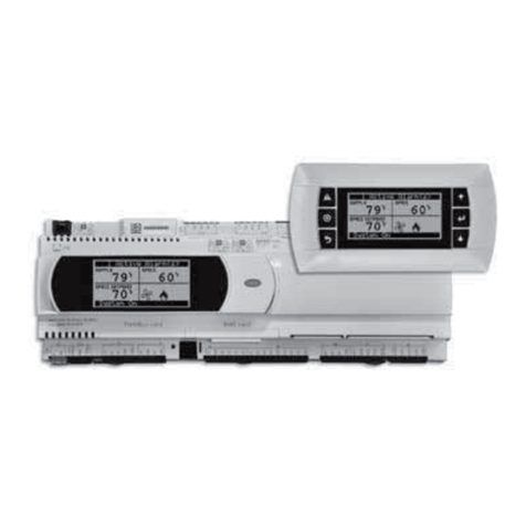
Hitecsa pGD User manual

USM_CONTROL_KRONO 3-MINI KRONO 3_208064_220501_EN
CONTROLLERS
pGD or Mini pGD
USER MANUAL
FOR UNITS: KRONO 3 (Kr3B)
Mini KRONO 3 (µKr3Bi)

2
Thank you for trusting the Hitecsa Products. Our company has been offering the market an extended range of
specialized equipment for air conditioning and cooling installations for over 35 years. Our approach is based on
efficiency, flexibility and practical solutions. This has been the hallmark of our product catalogue.
The versatility of our factory allows us to deliver solutions that can meet any requirement and we endeavour solving any
problem that may arise in designing and implementing air conditioning installations.
From all of us at Hiplus Aire Acondicionado, once again, thank you very much.

3
CONTROLLERS - CHILLERS and y HEAT PUMPS Air-Water
(Krono3; Mini Krono3)
INDEX
GENERAL SPECIFICATIONS...................................................................................................................4
INTERFACE CONNECTION......................................................................................................................5
OPERATION ..............................................................................................................................................6
USER INTERFACE................................................................................................................................................... 6
KEYS......................................................................................................................................................... 6
MAIN DISPLAY ......................................................................................................................................... 6
USER MENUS........................................................................................................................................... 7
MAIN MENU / SERVICE ..........................................................................................................................10
ALARMS ..................................................................................................................................................12

CONTROLLER
CHILLERS and HEAT PUMPS Air-Water
4
USM_CONTROL_KRONO 3-MINI KRONO 3_208064_220501_EN
GENERAL SPECIFICATIONS
The controller (name: W-HiReg) is meant to optimising the water chiller performance (cooling only or heat pump) and
comprises three parts:
1. Input/output board or electronical device, built in the equipment.
2. Control software.
3. User interface terminal or remote thermostat.
The control device of each chiller comprises mainly the above mentioned first two items and the user interface is a serial
terminal or is part of a BMS System. The terminal is a physical device but it may be a virtual device too with a TCP/IP
connection to the internet or an internal network.
The controller works independently from the user interface. The differences depend mainly on the version of the
controller software, the unit’s configuration and the fitted options.
The general specifications of the Air-Water chiller control system are as follows:
Control according to the inlet (or outlet) water temperature.
Time scheduler.
Network connection (master-slave)
Defrost operation control.
Working hours register for maintenance purpose of the compressors and water pumps when the unit is equipped
with that option.
Display of the inlet temperature and the input and output positions.
Compressor start-up scheduler.
Anti-frost protection.
High pressure security protection.
Compressor electronical protection.
Outdoor fan protection.
Protection by water differential switch (water cond. mode).
Remote ON/OFF.
Electronical expansion valves control.
Alarm control.

CONTROLLER
CHILLERS and HEAT PUMPS Air-Water
5
USM_CONTROL_KRONO 3-MINI KRONO 3_208064_220501_EN
INTERFACE CONNECTION
Terminal connection to a board with a 6 wire telephone cable (RJ12) at a max. 50 m distance. Connection between
several boards with a shielded pair.
For distances longer than 50 m and max. 200 m, proceed to interspersing with two TCONN devices.
PGD as
an option

CONTROLLER
CHILLERS and HEAT PUMPS Air-Water
6
USM_CONTROL_KRONO 3-MINI KRONO 3_208064_220501_EN
OPERATION
Access to the parameters, variables, configuration etc. through the keyboard and display of the THERMOSTAT (the user
interface) or through BMS.
USER INTERFACE
KEYS
or
ALARM KEY: Press to display the alarms on the screen. The red illuminated key shows that there
is an active alarm.
or
PROGRAM KEY: Press to enter the programming menu. (Restricted access with a password).
“ESC”KEY: From any sub-menu press to go back one level. From the main menu, access to the
Help function.
UP ARROW KEY: Scrolling through menus or control parameters modification.
“ENTER”KEY: Confirmation of the entered values.
DOWN ARROW KEY: Scrolling through menus or control parameters modification.
MAIN DISPLAY
Regulation
probe
Actual
Setpoint
Unit position
Operation mode
Date and hour
User menu
Modo de funcionamiento
Fecha y hora

CONTROLLER
CHILLERS and HEAT PUMPS Air-Water
7
USM_CONTROL_KRONO 3-MINI KRONO 3_208064_220501_EN
OPERATION
USER MENUS
The symbol that represents one of the available menus is displayed in the lower right corner. Scroll through the various
available menus by pressing the up or down arrow keys. Press “Enter” to access the displayed menu.
If you need to see/modify a value or a parameter, scroll through the menu until you reach the display that includes the
required value. Then press “Enter” until the cursor shows the value (each time you press “Enter”, the pointer will move
alternately between the various values). Modify the selected value by pressing the up or down key, then press “Enter” to
change the cursor position and confirm the modification. Finally press “Esc” to leave.
The available menus are as follows:
SYMBOL
DESCRIPTION
POSSIBLE ACTIONS
STOP/START menu (ON/OFF)
Start or stop the unit
COOL/HEAT menu
Modify the operation mode of the unit.
SETPOINT/set menu
Modify the temperature setpoints.
INFO menu
Display various values and positions.
TIME SCHEDULE menu
Modify the date and hour.
Time scheduler
ON/OFF menu
Select and press “Enter”.
The unit is in the Off position (Stop). Change the position by using the arrow keys. “Esc” to leave.
Cool/heat menu
Select and press “Enter”.
Select alternately one of the two operation modes: Cool or Heat
The unit is working in the cooling mode (left) or heating mode (right). Change the mode by using the arrow keys. “Esc”
to leave.

CONTROLLER
CHILLERS and HEAT PUMPS Air-Water
8
USM_CONTROL_KRONO 3-MINI KRONO 3_208064_220501_EN
OPERATION –User menus
TIME SCHEDULE menu
In addition to the mentioned basic operation modes, other functions are available from the time schedule menu.
Select and press “Enter”.
Follow the previously mentioned steps to complete the changes.
HOUR MODIFICATION
Modify the date and the actual hour.
TIME SCHEDULER
So as to enable time scheduling, proceed to changing from No to Yes. Once the programming function is enabled we
will be able to access the various options of the time Scheduler.
Temperature differential that will be applied depending on the various modes.
It is possible to program up to four events a day, each day of the week and four modes (OFF,
Comfort, Pre-Comfort and Economy) for each of the events. Change No to Yes to save the modifications. The selected
modes will be activated when the actual time matches the programmed hour and they will remain active until the next
scheduled event. The modes will be either Cooling or Heating depending on the selected modes for the hour when the
event starts.
Up to three annual periods may be scheduled. The selected mode for each period prevails over the daily mode that has
been selected.
A period of up to 6 days may be programmed with a single programmation. The selected mode for a special day will
prevail over the annual periods and the normal programmed days.
It is possible to select the “Auto” mode for a special day too.

CONTROLLER
CHILLERS and HEAT PUMPS Air-Water
9
USM_CONTROL_KRONO 3-MINI KRONO 3_208064_220501_EN
OPERATION –User menus
Setpoints menu
Select and press “Enter”.
The temperature setpoints can be modified for both operation modes.
Operation modes:
The main two operation modes are the Cooling mode and the Heating mode. Both modes have three operation levels
that apply a compensation to the values of the temperature setpoints.
Comfort Mode: Standard mode that does not apply any compensation to the Setpoint value.
Pre-Comfort Mode: A differential (Offset) is applied to the temperature setpoints. This differential is positive for the
Cooling mode and negative for the Heating mode.
Economy Mode: Another differential is applied to the temperature values. This differential is positive for the Cooling
mode and negative for the Heating mode.
The Setpoint value that we want to modify and the actual active value will be displayed on the screen. If the time
Scheduler is active, the modified Setpoint value will be displayed too with the applied compensation after adding the
corresponding offset (Comfort, Economy, Pre-comfort).
Modification of the cool and heat setpoints (without compensation). If the scheduler is active, the compensated value of
the setpoint will be displayed acccording to the active mode.
Indication of the target outdoor temperature from Cool to Heat and vice versa.
Values that shall be compensated according to the different modes of the time schedule. The value will be added to the
Cool setpoint or will be deduced from the Heat setpoint depending on whether the cooling mode or the heating mode is
active.
INFO menu
Select and press “Enter”.
Access to various graphical displays including information about the different components of the system:
Water circuit
Circulation pumps
Circuit pressures
Compressors
Fans
Electrical resistances
Defrost operations
Controller

CONTROLLER
CHILLERS and HEAT PUMPS Air-Water
10
USM_CONTROL_KRONO 3-MINI KRONO 3_208064_220501_EN
OPERATION
MAIN MENU / SERVICE
Enter the main menu by pressing the programming key “ ” o “ “. A password will be required to continue. The valid
password (service level) (only for installation) is “1996”.
MASTER-SLAVE CONFIGURATION
For interconnection of 2 to 5 units, the installer will need to configure one of them as the “Master” unit and the remaining
units will be “Slave” units.
Connect the pGD to the board of the chosen Master unit.
Enter the “Regulation” sub-menu. While keeping the “Enter” key pressed, go to “MS Type”.
While maintaining the cursor on “MS Type”, press the up/down arrow keys to change to “Master”.
Confirm and new fields will appear:
By pressing the “Enter” key we move to the field that we want to modify. Use the “up/down arrow” keys to change the
value.
(1) “Num. of units”: enter a number from 2 to 5.
(2) “RegType”: Chose the regulation type among the following options:
oAccording to the return temperature of the Master unit.
oAccording to the supply probe in the collector at the units’ outlet.
oAccording to the return probe of the most restrictive unit.
oAccording to the average data of the return probes of all the units.
Confirm the modifications by moving to “Update Config.?” and click to put the check mark “ ”.
After confirming by pressing “Enter”, we will need to confirm again from the following screen:
……..

CONTROLLER
CHILLERS and HEAT PUMPS Air-Water
11
USM_CONTROL_KRONO 3-MINI KRONO 3_208064_220501_EN
OPERATION - THERMOSTAT AND CONTROL –MASTER / SLAVE
Register the remaining units as Slave units by connecting the pGD in each unit: select Slave in the “MS Type” cell
and allocate a different “ID Slave” number to each unit.
Once the selection is made, proceed to confirming the modifications as you did for the Master unit and go to the next
Slave unit.
… …

CONTROLLER
CHILLERS and HEAT PUMPS Air-Water
12
USM_CONTROL_KRONO 3-MINI KRONO 3_208064_220501_EN
ALARMS
All the alarms displayed on the thermostat except the WARNING type alarms will make the unit stop.
Press the alarm key to access. It will display the active alarms first. Scroll through the various active alarms by using the
arrow keys. Press “Enter” from the last display to access the alarm history.
Alarm reset:
The Alarm key will be illuminated each time an alarm is active. Press that key to stop the sound alarm. By
pressing it again, the alarm will be deleted if the problem has been solved.
Please contact the technical assistance department if the alarm cannot be deleted.
How to reset the alarms:
Press (Alarm or ) to display information.
Press until the following screen appears:
Follow the displayed instructions:
Maintain the key pressed during three seconds to reset the alarms.
Description of the alarm messages:
ALARM MESSAGES
ACTION
Reset Alarms
-
Prb. Error - Water Inlet Temp.
Stops the whole unit
Prb. Error - Water Outlet Temp.
Stops the whole unit
Prb. Error - Water Outlet Temp. Circ.2
Stops the whole unit
Prb. Error - Water Tank Outlet Temp.
Stops the whole unit
Prb. Error - Exterior Temp.
Forces the fan setting to a fixed pressure (Factory).
Disables the defrost function of the fan and the tank resistance if
fitted.
Prb. Error - Flowmeter
Stops the whole unit
Prb. Error - Discharge Temp. Circ.1
Stops Circuit nº1
Prb. Error - Discharge Pressure Circ.1
Stops Circuit nº1
Prb. Error - Liquid Temp. Circ.1
-
Prb. Error - Suction Pressure Circ.1
Stops Circuit nº1
Prb. Error - Suction Temperature Circ.1
Stops Circuit nº1
Prb. Error - Discharge Temp. Circ.2
Stops Circuit nº2
Prb. Error - Discharge Press. Circ.2
Stops Circuit nº2
Prb. Error - Liquid Temp. Circ.2
-
Prb. Error - Suction Press. Circ.2
Stops Circuit nº2
Prb. Error - Suction Temp. Circ.2
Stops Circuit nº2
Prb. Error - Water Circuit Pressure
Stops the whole unit
DIN - Pump 1 Overload
Stops the unit unless there is rotation of the pumps. In that case
does not apply to that pump.
DIN - Pump 2 Overload
Stops the unit unless there is rotation of the pumps. In that case
does not apply to that pump.
DIN - Pump 3 Overload
Stops the unit unless there is rotation of the pumps. In that case
does not apply to that pump.
DIN - Compressor 1 Overload
Does not apply to that compressor
DIN - Compressor 2 Overload
Does not apply to that compressor

CONTROLLER
CHILLERS and HEAT PUMPS Air-Water
13
USM_CONTROL_KRONO 3-MINI KRONO 3_208064_220501_EN
ALARM MESSAGES
ACTION
DIN - Compressor 3 Overload
Does not apply to that compressor
DIN - Compressor 4 Overload
Does not apply to that compressor
DIN - Fans 1 Overload
Stops Circuit nº1
DIN - Fans 2 Overload
Stops Circuit nº2
DIN - FlowSwitch - Pump ON no flow
Stops the whole unit
DIN - FlowSwitch - Pump OFF flow
Does not allow the unit to start.
DIN - High Press. Pressostat Circ.1
Stops Circuit nº1, proceed to resetting the pressure switch physically
DIN - High Press. Pressostat Circ.2
Stops Circuit nº2, proceed to resetting the pressure switch physically
ENV. - High discharge pres. Circ.1
Stops Circuit nº1
ENV. - High discharge temp. Circ.1
Stops Circuit nº1
ENV. - Low discharge pres. Circ.1
Stops Circuit nº1
ENV. - High motor current Circ.1
Stops Circuit nº1
ENV. - High pressure ratio Circ.1
Stops Circuit nº1
ENV. - Low delta pressure Circ.1
Stops Circuit nº1
ENV. - Low pressure ratio Circ.1
Stops Circuit nº1
ENV. - High suction pres. Circ.1
Stops Circuit nº1
ENV. - Low suction pres. Circ.1
Stops Circuit nº1
ENV. - High discharge pres. Circ.2
Stops Circuit nº2
ENV. - High discharge temp. Circ.2
Stops Circuit nº2
ENV. - Low discharge pres. Circ.2
Stops Circuit nº2
ENV. - High motor current Circ.2
Stops Circuit nº2
ENV. - High pressure ratio Circ.2
Stops Circuit nº2
ENV. - Low delta pressure Circ.2
Stops Circuit nº2
ENV. - Low pressure ratio Circ.2
Stops Circuit nº2
ENV. - High suction pres. Circ.2
Stops Circuit nº2
ENV. - Low suction pres. Circ2
Stops Circuit nº2
EVD1 - Battery discharge
Stops the whole unit
EVD1 - EEPROM alarm
Stops the whole unit
EVD1 - Incomplete closing
Stops the whole unit
EVD1 - Emergency closing
Stops the whole unit
EVD1 - Firmware not compatible
Stops the whole unit
EVD1 - Configuration error
Stops the whole unit
EEVA - Low SuperHeat Circ.1
Stops Circuit nº1
EEVA - LOP Circ.1
Stops Circuit nº1
EEVA - MOP Circ.1
Stops Circuit nº1
EEVA - Motor error Circ.1
Stops Circuit nº1
EEVA - Low suction temp. Circ.1
Stops Circuit nº1
EEVA - High condensing temp.
Stops Circuit nº1
EEVB - Low SuperHeat Circ.2
Stops Circuit nº2
EEVB - LOP Circ.2
Stops Circuit nº2
EEVB - MOP Circ.2
Stops Circuit nº2
EEVB - Motor error Circ.2
Stops Circuit nº2
EEVB - Low suction temp. Circ.2
Stops Circuit nº2
EEVA - Ineffective adaptive control
Stops Circuit nº1
EEVA - Emergency closing alarm
Stops Circuit nº1
EEVA - Parameter range error
Stops Circuit nº1
EEVB - High condensing temp.
Stops Circuit nº2
EEVB - Ineffective adaptive control
Stops Circuit nº2
EEVB - Emergency closing alarm
Stops Circuit nº2
EEVB - Parameter range error
Stops Circuit nº2
Antifreeze Alarm
Stops the whole unit, pump is maintained and resistances are
started up
Antifreeze warning
Warning with the unit stopped, start-up of pump and resistances
Antifreeze Alarm Circ.1
Stops Circuit nº1, pump is maintained and resistances are started up
Antifreeze Alarm Circ.2
Stops Circuit nº1, pump is maintained and resistances are started up
High Pres. Alarm Circ.1
Stops Circuit nº1
Low Pres. Alarm Circ.1
Stops Circuit nº1
Minimum Pres. Alarm Circ.1
Stops Circuit nº1

CONTROLLER
CHILLERS and HEAT PUMPS Air-Water
14
USM_CONTROL_KRONO 3-MINI KRONO 3_208064_220501_EN
ALARM MESSAGES
ACTION
Refrigerant Leak Alarm Circ.1
Stops Circuit nº1
High Discharge Pres. Alarm Circ.2
Stops Circuit nº2
Low Suction Pres. Alarm Circ.2
Stops Circuit nº2
Minimum Suction Pres. Alarm Circ.2
Stops Circuit nº2
Refrigerant Leak Alarm Circ.2
Stops Circuit nº2
High Discharge Temp. Alarm Circ.1
Stops Circuit nº1
High Discharge Temp. Alarm Circ.2
Stops Circuit nº2
Water Flow Out of Limits
Stops the whole unit
Water Pressure Out of Limits
Stops the whole unit
Master Unit Offline
-
Slave Board Offline
-
EVD Drive Offline
Stops the whole unit
Energy Meter Offline
-
Fan 1 Offline
-
Fan 2 Offline
-
Fan 3 Offline
-
Fan 4 Offline
-
c.PCOe Offline
-
Slave Unit 1 Offline
-
Slave Unit 2 Offline
-
Slave Unit 3 Offline
-
Slave Unit 4 Offline
-
Maintenance Pump 1
-
Maintenance Pump 2
-
Maintenance Pump 3
-
Maintenance Comp 1
-
Maintenance Comp 2
-
Maintenance Comp 3
-
Maintenance Comp 4
-
Maintenance VE Circ.1
-
Maintenance VE Circ.2
-
Maintenance E.Heater Exchanger Circ.1
-
Maintenance E.Heater Exchanger Circ.2
-
Maintenance E.Heater W.Tank
-
Maintenance E.Heater Crankcase Circ.1
-
Maintenance E.Heater Crankcase Circ.2
-
Severe High Discharge Pres. Alarm Circ.1
Stops Circuit nº1, manual reset
Severe Low Suction Pres. Alarm Circ.1
Stops Circuit nº1, manual reset
Severe Minimum Suction Pres. Alarm Circ.1
Stops Circuit nº1, manual reset
Severe Refrigerant Leak Alarm Circ.1
Stops Circuit nº1, manual reset from factory
Severe High Discharge Pres. Alarm Circ.2
Stops Circuit nº2, manual reset
Severe Low Suction Pres. Alarm Circ.2
Stops Circuit nº2, manual reset
Severe Minimum Suction Pres. Alarm Circ.2
Stops Circuit nº2, manual reset
Severe Refrigerant Leak Alarm Circ.2
Stops Circuit nº2, manual reset from factory
Severe High Discharge Temp. Alarm Circ.1
Stops Circuit nº1, manual reset
Severe High Discharge Temp. Alarm Circ.2
Stops Circuit nº2, manual reset
Severe - FlowSwitch - Pump ON no flow
Stops the whole unit, manual reset
ENV. - Severe Low pressure ratio Circ.1
Stops Circuit nº1, manual reset
ENV. - Severe Low pressure ratio Circ.2
Stops Circuit nº2, manual reset
Severe - Water Flow Out of Limits
Stops the whole unit, manual reset
Severe - Antifreeze Alarm
Stops the whole unit, manual reset
Severe - Antifreeze Alarm Circ.1
Stops Circuit nº1, manual reset
Severe - Antifreeze Alarm Circ.2
Stops Circuit nº2, manual reset
Severe - Water Pressure Out of Limits
Stops the whole unit, manual reset
ZiehlFan MB 1 - Communication Error
Stops fan
ZiehlFan MB 1 - Motor Start Error
Stops fan
ZiehlFan MB 1 - Temperature Error
Stops fan
ZiehlFan MB 1 - Safety Shutdown
Stops fan

CONTROLLER
CHILLERS and HEAT PUMPS Air-Water
15
USM_CONTROL_KRONO 3-MINI KRONO 3_208064_220501_EN
ALARM MESSAGES
ACTION
ZiehlFan MB 1 - Sinefilter
Stops fan
ZiehlFan MB 1 - Peak Current
Stops fan
ZiehlFan MB 1 - Motor Blocked
Stops fan
ZiehlFan MB 1 - Hallsensor Error
Stops fan
ZiehlFan MB 1 - TB Error
Stops fan
ZiehlFan MB 1 - Line Fault
Stops fan
ZiehlFan MB 1 - UIN LO
Stops fan
ZiehlFan MB 1 - UIN HI
Stops fan
ZiehlFan MB 1 - UZK LO
Stops fan
ZiehlFan MB 1 - UZK HI
Stops fan
ZiehlFan MB 1 - Earth to ground fault
Stops fan
ZiehlFan MB 1 - IGBT Fault
Stops fan
ZiehlFan MB 1 - Functional Safety - Full Safe Mode
Stops fan
ZiehlFan MB 1 - Motorcontrol Sys Warning
Stops fan
ZiehlFan MB 1 - User App Sys Failure
Stops fan
ZiehlFan MB 1 - Vibration Error
Stops fan
ZiehlFan MB 1 - Lifetime Error
Stops fan
ZiehlFan MB 1 - Direction Error
Stops fan
ZiehlFan MB 1 - Limitations active
Stops fan
ZiehlFan MB 2 - Communication Error
Stops fan
ZiehlFan MB 2 - Motor Start Error
Stops fan
ZiehlFan MB 2 - Temperature Error
Stops fan
ZiehlFan MB 2 - Safety Shutdown
Stops fan
ZiehlFan MB 2 - Sinefilter
Stops fan
ZiehlFan MB 2 - Peak Current
Stops fan
ZiehlFan MB 2 - Motor Blocked
Stops fan
ZiehlFan MB 2 - Hallsensor Error
Stops fan
ZiehlFan MB 2 - TB Error
Stops fan
ZiehlFan MB 2 - Line Fault
Stops fan
ZiehlFan MB 2 - UIN LO
Stops fan
ZiehlFan MB 2 - UIN HI
Stops fan
ZiehlFan MB 2 - UZK LO
Stops fan
ZiehlFan MB 2 - UZK HI
Stops fan
ZiehlFan MB 2 - Earth to ground fault
Stops fan
ZiehlFan MB 2 - IGBT Fault
Stops fan
ZiehlFan MB 2 - Functional Safety - Full Safe Mode
Stops fan
ZiehlFan MB 2 - Motorcontrol Sys Warning
Stops fan
ZiehlFan MB 2 - User App Sys Failure
Stops fan
ZiehlFan MB 2 - Vibration Error
Stops fan
ZiehlFan MB 2 - Lifetime Error
Stops fan
ZiehlFan MB 2 - Direction Error
Stops fan
ZiehlFan MB 2 - Limitations active
Stops fan
ZiehlFan MB 3 - Communication Error
Stops fan
ZiehlFan MB 3 - Motor Start Error
Stops fan
ZiehlFan MB 3 - Temperature Error
Stops fan
ZiehlFan MB 3 - Safety Shutdown
Stops fan
ZiehlFan MB 3 - Sinefilter
Stops fan
ZiehlFan MB 3 - Peak Current
Stops fan
ZiehlFan MB 3 - Motor Blocked
Stops fan
ZiehlFan MB 3 - Hallsensor Error
Stops fan
ZiehlFan MB 3 - TB Error
Stops fan
ZiehlFan MB 3 - Line Fault
Stops fan
ZiehlFan MB 3 - UIN LO
Stops fan
ZiehlFan MB 3 - UIN HI
Stops fan
ZiehlFan MB 3 - UZK LO
Stops fan
ZiehlFan MB 3 - UZK HI
Stops fan
ZiehlFan MB 3 - Earth to ground fault
Stops fan
ZiehlFan MB 3 - IGBT Fault
Stops fan

CONTROLLER
CHILLERS and HEAT PUMPS Air-Water
16
USM_CONTROL_KRONO 3-MINI KRONO 3_208064_220501_EN
ALARM MESSAGES
ACTION
ZiehlFan MB 3 - Functional Safety - Full Safe Mode
Stops fan
ZiehlFan MB 3 - Motorcontrol Sys Warning
Stops fan
ZiehlFan MB 3 - User App Sys Failure
Stops fan
ZiehlFan MB 3 - Vibration Error
Stops fan
ZiehlFan MB 3 - Lifetime Error
Stops fan
ZiehlFan MB 3 - Direction Error
Stops fan
ZiehlFan MB 3 - Limitations active
Stops fan
ZiehlFan MB 4 - Communication Error
Stops fan
ZiehlFan MB 4 - Motor Start Error
Stops fan
ZiehlFan MB 4 - Temperature Error
Stops fan
ZiehlFan MB 4 - Safety Shutdown
Stops fan
ZiehlFan MB 4 - Sinefilter
Stops fan
ZiehlFan MB 4 - Peak Current
Stops fan
ZiehlFan MB 4 - Motor Blocked
Stops fan
ZiehlFan MB 4 - Hallsensor Error
Stops fan
ZiehlFan MB 4 - TB Error
Stops fan
ZiehlFan MB 4 - Line Fault
Stops fan
ZiehlFan MB 4 - UIN LO
Stops fan
ZiehlFan MB 4 - UIN HI
Stops fan
ZiehlFan MB 4 - UZK LO
Stops fan
ZiehlFan MB 4 - UZK HI
Stops fan
ZiehlFan MB 4 - Earth to ground fault
Stops fan
ZiehlFan MB 4 - IGBT Fault
Stops fan
ZiehlFan MB 4 - Functional Safety - Full Safe Mode
Stops fan
ZiehlFan MB 4 - Motorcontrol Sys Warning
Stops fan
ZiehlFan MB 4 - User App Sys Failure
Stops fan
ZiehlFan MB 4 - Vibration Error
Stops fan
ZiehlFan MB 4 - Lifetime Error
Stops fan
ZiehlFan MB 4 - Direction Error
Stops fan
ZiehlFan MB 4 - Limitations active
Stops fan

Subject to modification without prior notice.
This manual suits for next models
1
Table of contents
Other Hitecsa Controllers manuals
