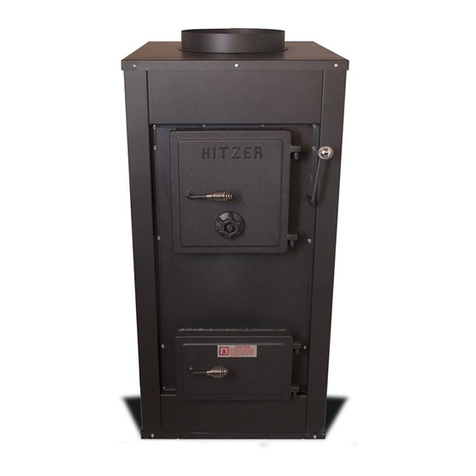
Hitzer Energy Master II 710 User manual

Page 1
Hitzer Energy Master II Stoker Furnace
Model 710
Owner’s Manual
Installation and Operation
Save this Manual
Operating Instructions and Maintenance Enclosed.
Thoroughly Read and Understand Instructions.
Always Leave this Manual with Stove Owner.
Warning
FOLLOW THE INSTRUCTIONS WITHIN THIS MANUAL. IF
INSTRUCTIONS ARE NOT FOLLOWED, A FIRE MAY RESULT CAUSING
PROPERTY DAMAGE, PERSONAL INJURY, OR EVEN DEATH. REFER
TO MARKINGS ON THE FURNACE FOR ADDITIONAL INFORMATION.
CARBON MONOXIDE AND SMOKE DETECTORS/ALARMS MUST BE
INSTALLED IN THE HOME AND WORKING PROPERLY
DANGER –RISK OF FIRE OR EXPLOSION
DO NOT BURN GARBAGE, GASOLINE, DRAIN OIL, OR OTHER
FLAMMABLE LIQUIDS. DO NOT USE CHEMICALS OR FLUIDS TO
START FIRE
BURN RICE SIZE ANTHRACITE COAL ONLY
STOVE SURFACES MAY BE HOT WHILE IN OPERATION. KEEP
CHILDREN AWAY. DO NOT TOUCH DURING OPERATION.
DO NOT CONNECT THIS UNIT TO A CHIMNEY FLUE SERVING
ANOTHER APPLIANCE
DO NOT OPERATE WITH FLUE DRAFT EXCEEDING .06 WC (14.945 Pa)

Page 2
Table of Contents
I. Welcome to Hitzer Family
A. Safety Notice
II. Location of Stove & Installation
A. Pre Installation Information
B. Location
C. Clearances To Combustibles/Floor Protection
D. Requirements In Regards To Installation
E. Connecting Furnace To Chimney
III. Typical Installation
A. Illustrations
B. Supply Duct
C. Return Air
D. Combustion Air
E. Installation In A Confined Space
IV. Flue Systems
A. Masonry System
B. Factory Built Systems
C. Chimney Requirements
D. Flue Size
E. Chimney Height Requirements
F. Power Vent System
V. Basic Regulations for Safe Operations
A. Cautions
B. Local Codes
VI. Stove Start Up & Operation
A. Install Coal-Trol Thermostat
B. Start Up
C. Adjusting Chimney Draft
D. Measuring Furnace Compatibility
VII. MAINTENANCE
A. Daily
B. Weekly
C. Two Months
D. End Of The Season
E. Power Outages
VIII. TROUBLESHOOTING
IX. Further Information

Page 3
I. Welcome to Hitzer Family
Hitzer Inc. welcomes you to a proud and unified team of Hitzer stove owners. Thank You for your recent
purchase of a Hitzer Energy Master II Stoker Furnace. We can assure that your Hitzer furnace has the
finest Swiss Amish Craftsmanship. Your Hitzer Energy Master II Furnace is built with premium quality
materials to ensure safety, durability, and performance. These are all top priorities in the Hitzer line of
products.
We would like to personally thank you again and welcome you into our continually growing Hitzer Family.
We wish you and your family an extended amount of warmth and comfort, provided by your new Hitzer
Furnace. Thanks for choosing Hitzer where our motto is:
“Our Stoves Make Warm Friends.”
Safety Notice
Safety Notice: If this Hitzer Stove is not properly installed a house fire may result. For your safety and to
reduce the risk of fire, follow the installation instructions carefully. Failure to follow these instructions may
result in property damage, bodily injury, or even death. Contact your local building inspector or fire
officials about the need for a permit, restrictions, or installation inspection required in your area. Refer to
makings on your furnace for more information. Save these instructions for future reference.
Safety Notice: Always have working carbon monoxide and smoke detectors installed when using this
equipment. It is recommended to have one on each floor of the house and outside of sleeping rooms.
UL Tested/Label: Follow the information and clearance charts located on each Hitzer Stove Model. This
furnace has been tested to UL 391-2006 & CSA B366.1-M91, approved, and labeled on the rear of each
stove.
It is strongly recommended to have this Hitzer Furnace installed by an educated and certified professional
heating contractor. Please refer to a NFI (National Fireplace Institute) Certified Installer for your
installation needs and questions. Locate an NFI professional at www.nficertified.org.

Page 4
II. Location of Stove & Installation
Pre Installation Information:
Your Energy Master Furnace is intended for use in residential buildings. Do not install in a mobile home.
Do not install in a garage.
IMPORTANT: Always check with local authorities and obtain the necessary permits prior to
installing this furnace. This furnace must be installed in accordance with local, state, and national
codes and regulations.
Before installation some questions must be addressed.
1. Will your Energy Master Furnace be used as a primary (central) furnace, or will it be installed as an
add-on to your existing central heating system?
2. If your Energy Master Furnace is to be installed as an add-on, is it compatible with your existing
furnace? Your Energy Master Furnace is designed to be used with a listed gas-, oil-fired furnace
however not all furnaces will accept add-on applications. Some small furnaces, and especially counter-
flow or down-flow furnaces, can not be used in an add-on installation. The CFM (cubic feet per minute)
capability between the blower on the existing furnace and the add-on furnace must be compatible. If all
these conditions are met then the combined static pressure must not exceed the maximum static
pressure listed on the nameplate on either furnace. Before installing your Energy Master Furnace consult
your Hitzer dealer or heating contractor and your local, state and national building codes and regulations
to determine if your central heating system is compatible with your Hitzer Energy Master Furnace. Once it
is determined your existing furnace will accept an add-on installation a parallel installation with return air
(outlined later in this manual) is recommended.
3. Can the furnace be vented properly?
a. Is the chimney appropriate for this installation? This furnace requires installation in a masonry
chimney with a clay flue liner or a metal all-fuel chimney listed to UL103 (CAN/ULC-S629-M87) Type HT.
Do not connect this furnace to a chimney serving another appliance!
b. Has your chimney been inspected? It is important that your chimney is clean and structurally sound
(free from defect or damage) before installing your Energy Master Furnace.
c. If you are power venting your furnace is there a place to mount the power vent away from
obstacles? Refer to power vent placement chart with power vent instructions.
4. Is there easy access to outside combustion air should your furnace require it?
5. Can the furnace be installed safely?
a. This furnace must not be installed in a location where it could come in contact with walls, carpeting,
curtains/drapes, or other combustible surfaces.
b. The clearances listed in this manual and on the furnace are minimum clearances. Any reduction
must be approved by the regulatory authority and is not recommended by Hitzer Inc.
c. Will this location require floor protection?
d. Furnace must not be installed in a sleeping room.
6. How close is the electrical source and does it conform to requirements listed?
7. Are there any local, state, or national codes or regulations concerning the use and placement of your
furnace?
8. Are there any structural reasons why the furnace cannot be located where you want it?
9. Will the furnace be easily accessible for refueling, cleaning, maintenance, and repair?

Page 5
Location:
The location of the stove is very important for optimum stove performance as well as safety assurance.
When searching for the location of the stove be sure to strictly follow manufactures guidelines,
clearance to combustible material requirements, local building, and fire codes. Failure to follow
manufacture’s instruction and local jurisdiction codes may result in bodily injury, property
damage, fire, or death. Locate the stove where there is sufficient air supply for proper operation to
occur. It is vitally important to locate the stove next to existing forced air furnace as well as next to the
chimney, or exterior wall for power vent systems. The closer placement to these two items the better the
stove will perform, and achieve maximum heat flow. The longer the chimney connector pipe (stovepipe)
and farther away the furnace is from the chimney or power vent the less performance is achieved from
the furnace. Please consider the construction and layout of the home to be heated and make placement
of the Energy Master Furnace to achieve maximum heat benefit it can produce.
Clearances To Combustibles/Floor Protection:
This furnace must be placed on a non-combustible floor. If the floor is a combustible material floor
protection must be placed underneath it and extend at least 8 inches on each side of the fuel or ash door.
It must also extend 16 inches out from the front of the furnace. The floor protection must also be placed
underneath the chimney connector (stove pipe) and extend at least 2 inches on either side of the chimney
connector. This protection is for hot ash and sparks. It is not needed for heat protection. If your furnace is
installed on a concrete basement floor, it is recommended to install on a 2 inch thick nonflammable
material. This will reduce contact with the damp floor that can cause possible rust and corrosion.
Back wall
2”
Minimum Clearance to Combustible Material: Floor Protection:
Unit to Side Wall: 2 inches Front: 16 inches
Unit to Back Wall: 6 inches Side: 8 inches from
Chimney Connecter to Back Wall: 18 inches either side of the
Chimney Connecter to Side Wall: 18 inches fuel and ash door
Rear: 2 inches
Furnace
Floor Protection
16 “
8”
6”
2”

Page 6
CAUTION: It is mandatory to abide by clearance to combustibles regulations provided on the
furnace label and in this instruction manual. Failure to abide by the clearance requirements may
result in a fire.
Requirements In Regards To Installation:
DO NOT connect to a chimney serving another appliance. Only one appliance is to be used per
chimney.
Flue must be the same size as stove flue collar or larger within requirements of flue size
maximums.
Chimney connector pipe (stove pipe) must be made of at least 24 gauge metal and be attached
with crimped ends facing the stove. A minimum of 3 screws is required at each connection point.
Masonry or manufactured thimble must be longer than the thickness of the wall and does not
intrude past the inner face of the chimney liner.
Thimble may be constructed of approved clay liner thimble tested and labeled. With a 12” non-
combustible clearance zone on each side of thimble. Please use NFPA 211 instructions and
requirements in regarding thimble information.
Thimble may be a manufactured thimble or class A chimney pipe. A manufactured component
must be installed with listed components accessories and meet manufacturer’s specifications.
It is required to have thimble clearances to combustible material as required by manufacturer and
NFPA 211.
NFPA 211 codes must be followed and an 18” clearance to combustible material is required for
chimney connectors.
This unit must be installed on a noncombustible floor according to the measurements above.
DO NOT install in a garage.
Connecting Furnace To Chimney:
Connection of your Energy Master Furnace to the chimney should be made as direct as possible. It is not
recommended to use more then 2 elbows for venting. The pipe connecting the furnace to the chimney
should be at least 24 gauge single wall pipe. Thicker gauges and double wall pipe may be used. A ½
inch slope, back toward the furnace, per foot of horizontal run is required. This allows any condensation
forming in the pipe to flow back toward the furnace. The connection pipe should be installed so the upper
pipe fits inside the lower pipe. Horizontal run pipe should have the seam turned up. Note the point at
which the flue passes through a wall to the chimney. This penetration must be made with an approved
through the wall thimble or class A chimney pipe and used with the listed proper accessories according to
manufacturer’s instructions. Chimney connector (stove pipe) CANNOT pass through a ceiling, wall, or any
concealed space. Three screws must be attached at each connection point of the chimney connector.
When the Class A chimney pipe connects to the masonry, it must be cemented to the chimney, or a
thimble must be connected to the chimney and the pipe should be tightly inserted into the thimble without
cementing.
III. Typical Installations
Illustrations:
Below are typical ways of installation formats. Note: these illustrations reflect typical installations and are
for design purposes only. Illustrations and diagrams are for informational purposes only. These diagrams
are not drawn to scale. Actual installation procedures may vary.
NOTE: It is always best to run the supply duct up. The supply duct must be constructed of material with
a minimum 250°temperature rating. With the supply duct up, this will allow gravity heat to still rise into
the system. The plenum on the furnace must be constructed of metal.

Page 7

Page 8
Notice: Installations are drawn with a masonry chimney. Manufactured metal chimney listed to UL 103
(CAN/ULC-S629-M87) Type HT or a Hitzer approved power vent system may also be used. Follow
manufacturer’s instructions/guidelines when using these products.

Page 9
Supply Duct:
In order to achieve maximum performance it is important to have the correct size of duct work that
corresponds with your Hitzer ENERGY MASTER Stoker Furnace. Your furnace is equipped with a 1009
CFM Blower. In order to achieve maximum performance and heat, it is important to make sure the duct
work is sized properly and not too small for the blower assembly. If the duct work is too small your furnace
won’t achieve full potential. Duct sized excessively large will also be detrimental to the operation of your
furnace. NOTE: These calculations are based on a .10 static pressure.
Supply Duct Size Shape Approximate Capacity(CFM)
6” round 120
8”round 240
10” round 420
12” round 680
14” round 1000
8”x12” rectangle 480
8”x16” rectangle 700
8”x 20” rectangle 910
8”x 22” rectangle 1000
8”x 24” rectangle 1200
Return Air:
Return air is very important and MUST BE incorporated into the system. Without adequate return air
supplied to your furnace the warm air distributed into your home will be restricted. This will decrease the
efficiency of your furnace. You could also cause the furnace to overheat because of reduced air flow
causing damage to your unit and voiding your warranty. If your furnace is installed in a basement or utility
room that is fairly air tight the blowers on the furnace could depressurize the room and pull toxic flue
gasses from the furnace or other burning appliance in the area. These toxic fumes could then be
distributed throughout the house causing a very dangerous situation.
The return air can be provided by installing a separate duct system or by tying into the cold air return duct
of the existing furnace. Without a return air system warm air will be drawn into your basement,
unnecessarily heating unused portions of your home. The return duct should be a minimum of 16” x 20”
or equivalent (320sq.in.). The return duct may be attached to the rear of the stoker furnace. Make sure if
you are attaching the duct to the rear of the furnace you do not inhibit the removal and replacement of the
furnace filters. These filters should be checked and cleaned/replaced regularly to maintain the proper air
flow.
Combustion Air:
All fires need air to burn. The incomplete combustion that takes place in an “air starved” situation causes
carbon monoxide (CO) to be produced in quantities that can be dangerous inside a well sealed house.
Having a source of combustion air from outside the home will prevent “air starvation” of the furnace. You
must provide enough fresh air to assure proper combustion. Outside air is required to replace air used to
take the byproducts of combustion out the chimney. Outside air is also required to replace air exhausted
by kitchen/bathroom fans, and any other furnace, or water heater chimneys or fans.
Outside air may be needed if:
The solid-fuel-fired appliance does not draw steadily, smell, experiences smoke roll-out, burns
poorly, or back-drafts whether or not there is combustion present.
Any of the above symptoms are alleviated by opening a window slightly on a calm day.
The house is equipped with a well-sealed vapor barrier and tight fitting windows and/or has any
powered devices which exhaust house air.
There is excessive condensation on windows in the winter.
A ventilation system is installed in the house.
Installation In A Confined Space:
When the furnace is installed in a utility/storage room or other enclosed areas you must install two open
grills. They should be placed in a wall or door opening into the rest of the house. One will supply
combustion air. Locate it near the floor. The other is for ventilation and be located near the ceiling. Each

Page 10
grill must have free area. This open area should not be less than 1 square inch for each 1000 BTU/hr of
the total input rating of all the appliances in the confined space.
CAUTION: ANY FANS/BLOWERS INSTALLED IN THE ROOM WITH YOUR ENERGY MASTER
STOKER FURNACE MUST NOT CREATE A NEGATIVE PRESSURE IN THAT ROOM
Typical Wrong Installation
Do not have supply hot air flow downward as this will not allow the Hitzer Furnace to operate properly.
Do not have the supply air flow back into the blower of existing oil or gas furnace. This could damage the
existing furnace controls and/or void any warranty.
Do not have hot air from gas or oil furnace flow downward into the Hitzer Furnace and flow out the Hitzer
Furnace to existing duct work.
Additional Safety Requirements for Canadian Supplemental (add-on) Furnace Installations:
Do not use duct elbows having an inside radius of less than 6in (150mm) on the (oil, gas,
electric) furnace.
Do not connect to a down flow furnace.
Do not connect ductwork so that a reverse flow is possible.
Operate the (gas, oil, electric) furnace periodically to ensure it will operate satisfactorily when
needed.
Certified for installation with the ductwork configurations shown previously.
Do not relocate or bypass any of the safety controls in the original (gas, oil, electric) furnace
installation.
Do not connect to any furnace that has not been certified initially as complying with CAN/CGA-
2.3
The operation of the gas furnace must be verified for acceptable operation before and after
installation of the add-on appliance by a gas fitter who is recognized by the regulatory
authority.
DO NOT connect to any gas furnace that is not equipped with an air-circulation blower,
DO NOT connect to or a chimney or vent serving a gas furnace or gas appliance.

Page 11
This installation should comply with requirements of CAN/CSA-B365, and changes are made
to the central furnace, changes must comply with CSA B139 (for oil-fired), C22.1 (for electric),
or CAN/CGA-B149.1 or CAN/CGA-B149.2 (for gas-fired).
This add-on furnace must only be installed on a furnace duct system and chimney that are in
good operating condition.
IV. Flue Systems
Masonry Flue System: A good chimney is essential. A masonry chimney must be built with a low heat
masonry material. It is important to make sure that the masonry chimney is structurally sound and on a
solid foundation. The masonry chimney must have a liner installed within the chimney construction. An
unlined chimney is not safe with solid fuel systems, and may result in a house fire. The liner may be a
structurally sound clay liner or a stainless steel liner. If using an existing masonry chimney, be sure to
have the chimney examined and cleaned by a chimney professional. The structural foundation of the
chimney and liner are important. If the existing clay liner is cracked or damaged, it is recommended to re-
line the chimney with a stainless steel liner or other chimney relining system. Be sure the masonry
chimney is compatible with the local building codes and requirements. It is important to note that you can
only have one appliance per chimney, and it is not permissible to connect your Hitzer Energy Master II
furnace to a chimney that is servicing another appliance.
Factory Built System:
A good chimney is essential. The factory built chimney must be a Class A: High Temperature chimney UL
listed to UL 103 (CAN/ULC-S629-M87) Type HT. It is required for this Class A chimney to be listed and
labeled under the UL standards. If using an existing factory built Class A chimney it must be inspected
and cleaned by a certified chimney professional, before use. With Factory Built Chimneys, clearances
and distance requirements are required per chimney style. Be sure to follow the manufacturer’s
clearances and regulations. It is also important to abide by the rules and regulations of local jurisdictions
upon chimney installation. Like masonry chimneys, you can only have one appliance per chimney, and it
is not permissible to connect your Hitzer Energy Master II furnace to a chimney that is servicing another
appliance.
Flue Requirements: It is required to have a chimney that is built according to the chimney
manufacturer’s specifications and meets local building codes. It is also required to have your chimney
inspected and cleaned by a certified chimney professional before your Hitzer Energy Master II furnace
installation, and periodically during the heating season. When wood is burned slowly, it produces tar and
other organic vapors, which combine with expelled moisture to form creosote. The creosote vapors
condense in the relatively cool chimney of a slow-burning fire. As a result, creosote residue accumulates
on the flue lining. When ignited, this creosote makes an extremely hot fire, the results of which can be
tragic. If material has accumulated, it should be removed immediately to reduce the risk of a chimney fire.
An Anthracite coal fire, as a general rule, does not produce creosote so it should not add to a creosote
buildup. It can however get hot enough to ignite an existing buildup thus causing a chimney fire.
IF A CHIMNEY FIRE DOES OCCUR: Notify all the occupants of the house and call the fire department
immediately. Turn the power to the furnace turned off, and any draft controls should be closed. The
barometric damper should be blocked then exit the house at once!
Flue Size: The proper flue size is very important. The proper flue size is essential in order to have the
correct amount of draft required to operate the Hitzer Furnace. The diameter of the flue size including
chimney liner should never be less than the diameter of the flue exhaust collar on the Hitzer Furnace. The
flue size for the Stoker Furnace should be a minimum of 6 inches in diameter
The flue size also has a maximum size of inches in order to sustain the desired draft. For an interior
chimney the flue and chimney liner size cannot be larger than 3 times the square inches of the flue
exhaust collar on the Hitzer stove. For an exterior chimney that has at least one side exposed to the
exterior of the house the flue and chimney liner cannot be more than 2 times the square inches of the
flue exhaust collar of the Hitzer Furnace. Also keep in mind the warmer the chimney is the better the
draft.

Page 12
Model Flue Size (Sq. Inch) Minimum (Sq. inch) Maximum (Sq. Inch)Int/Ext
Stoker 6” 28 sq. in. 6” 28 sq. in. 84 sq. in. interior
Furnace 6” 28 sq. in. 6” 28 sq. in. 56 sq. in. exterior
Chimney Height Requirements: The minimum height of a chimney system for the Hitzer Stove is 15
feet. The chimney must exceed the roof of a house a minimum of 3 feet at any point of exit. In pitched
roof installation the chimney must be at least 2 feet higher than anything within a 10 foot radius of the
chimney. It is important to have a chimney draft of .03 - .06 wc. Never operate your furnace at a flue draft
exceeding .06 wc (14.945 Pa) or less than .03wc (7.473 Pa). It is required to abide by the manufacture’s
instructions on class A chimney’s as well as local building codes.
All of these requirements must be followed to ensure the best chances for good draft. There are however
many environmental factors that can effect your draft. A few of these include wind speed and direction,
obstructions diverting winds, barometric pressure and humidity. This is why it is essential to have a
barometric damper and carbon monoxide detectors/alarms installed and working properly.
Power Vent System:
A Hitzer approved power vent may be used in place of a chimney. BE SURE TO READ YOUR POWER
VENTER INSTALLATION AND OPERATION INSTRUCTION MANUAL BEFORE USING THE POWER
VENTER. Follow the instructions that come with the power venter, for cutting the hole, and mounting the
venter to the wall. Connect your Hitzer Energy Master II Stoker Furnace to the power vent using a 6 inch
stove pipe and a barometric damper. You need to make certain that the pipe joints are tight together and
screwed with a minimum of three sheet metal screws per joint. Once you have the vent system
installed you can then install the wall control thermostat system according to the COAL-TROL
DIGITAL™ instruction manual which is supplied in the thermostat box.
Note:
-Illustrations are not drawn to
scale
-For design purposes only
-Actual Installations may vary

Page 13
IV. Basic Regulations for Safe Operations
Standard Cautions:
CAUTION: ALWAYS HAVE WORKING CARBON MONOXIDE AND SMOKE
DETECTORS/ALARMS INSTALLED WHEN USING THIS APPLIANCE. ONE ON
EACH FLOOR AND BY SLEEPING ROOMS IS RECOMMENDED
CAUTION- Hot Surfaces WARNING-Risk of Fire
-Keep children away Do NOT operate with fuel or ash door open
-Do not touch during operation Do NOT store fuel or other combustible
material within marked installation clearances
DANGER-Risk of Fire/Explosion
- Burn Rice Anthracite Coal Only
-Do NOT burn garbage, gasoline, Do NOT connect this unit to a chimney flue
oil, or any other flammable liquids serving another appliance.
CAUTION WARNING
Use caution when opening loading door. Have chimney inspected. The chimney
Avoid opening loading door rapidly. This is a very important part of your heating
could cause flame to flash out door. This system. It must be the right size,
occurs when there is unburned gas at the properly constructed, and in good
top of the fire box. When the door is condition. Chimney must be at least 15’
opened, oxygen combines with gases high and exceed the roof a minimum of
and ignites. 3 feet, unless using Power Vent System
WARNING-Risk of Fire WARNING-Over Fire Unit
-Comply with all minimum clearances to Do NOT over fire your unit.
combustibles as specified. This will cause warping of fire box parts,
-Failure to comply may cause fire. damage the stove, and void all warranty.
Local Codes:
All local codes should be strictly followed and inspected by local officials. Please follow local building
codes, manufacture codes, and fire codes. Local codes vary depending on location and regulations.
Communication and inspection in accordance with local building and fire officials must be present and
installation must successfully pass the local professional inspection.
VI. Stove Start Up & Operation
Install Coal-Trol Thermostat:
Once appliance is placed in the desired location you can locate your Coal-Trol thermostat so that the
supplied control cable will reach it. The supplied cable is 25 feet long. Longer lengths can be ordered

Page 14
from your Hitzer dealer or directly from Hitzer. The maximum length that will work is 100 feet. The Coal-
Trol control box is located on the top of the blower housing. Connect control cable to thermostat on the
wall and to the control box on the furnace. Once the ductwork has been connected mount hi-temperature
cut out switch (set to 155°) in ductwork approximately 3 inches above the furnace top. Drill 1” hole in duct
and mount switch with sensor inside duct. Follow the instructions and set-up procedure included with the
Coal-Trol Thermostat.
Start Up:
Note: For the first fire in your new Hitzer Furnace, create a small hot fire to allow paint to cure to the
stove. This may create a slight odor as paint cures to the furnace. Let this small fire burn for at least 2
hours before you raise the Coal-Trol temperature setting to maximum heating potential.
CAUTION: NEVER USE GASOLINE, KEROSENE, CHARCOAL LIGHTER FLUID, OR
ANY OTHER TYPE OF FLAMMABLE LIQUID TO START YOUR FIRE.
First make sure you have coal in the hopper and the power vent on if applicable. In the center of the
grate build a fire with broken up self lighting charcoal, a big hand full of wood pellets, a coal stoker igniting
block (coal mouse), or kindling wood. Once the fire is started and established, sprinkle a very thin layer of
coal over it and turn the power on to the COAL-TROL DIGITAL™ control. This starts the combustion
blower and also the feed motor. As you see the coal start to glow sprinkle another layer of coal on. As this
coal starts to glow red the feed motor should now be feeding coal far enough onto the grate that it will
start. Once coal is started you can adjust the thermostat to the desired temperature and the automatic
system will take over from here.
Adjusting Chimney Draft:
With the coal fire burning and stabilized, drill a small hole in the back of the stovepipe a few inches above
your furnace. Attach a manometer to this hole to read the chimney draft. Adjust the barometric damper so
that your manometer reads between .03 and .06 (inches of water column) following the instructions
provided with the damper. Do not run at a draft above .06 (inches of water column) as this could cause
your stoker to over fire. Over firing can cause a dangerous fire hazard. It would be best to set it with a
manometer if available. The settings on the barometric damper are close but not completely accurate.
Measuring Furnace Compatibility:
Follow the instructions with your Coal-Trol to find the fan speed adjustment. Adjust this from automatic to
manual at 99. This is the max speed of the convection fan. At the same time adjust the thermostat on
your central furnace 8 to 10 degrees above the room temperature. This should in a few minutes have it’s
fan running at max. With both fans running at their maximum settings, Drill a small hole in the plenum of
each furnace and measure the static pressure in each with a manometer. The maximum static pressure
must not exceed the pressure listed on the nameplate of the furnaces. If these pressures are exceeded
your installation is incorrect and dangerous. Exceeding these pressures will void your warranties and
possibly damage either one or both of your furnaces. This problem can be easily fixed by enlarging your
duct work or possibly adding another line to your plenum. .
Notice: Always burn your stoker with the ash door, glass door, and hopper lid closed and the door
gaskets and seals in good condition. Failure to keep these doors closed can result in smoke and carbon
monoxide coming into your house creating a very dangerous situation
CAUTION: ALWAYS HAVE A WORKING CARBON MONOXIDE, AND SMOKE
DETECTOR INSTALLED WHENEVER USING THIS APPLIANCE
CARBON MONOXIDE
Actuation of your CO alarm indicated the presence of Carbon Monoxide. Turn off your coal stove
immediately and increase ventilation by opening windows and doors to help move the fresh air
throughout the house. Exit the area at once. Contact your installer or other local authorities to
determine the source of the carbon monoxide and solve the problem.

Page 15
VII. Maintenance
Failure to maintain or properly use this appliance may cause a house fire. At the beginning of each
heating season this appliance, the connector pipe, and chimney should be inspected to see that it is in
good working condition.
Daily:
Check ash pan and remove and dump if full. Failure to remove ashes will result in ashes blocking
up your grate and your fire will not burn correctly. Ash pan will fill within several days depending
on the burn rate. Ashes should be placed in a metal container with a tight fitting lid. The closed
container of ashes should be placed on a noncombustible floor or on the ground, well away from
all combustible materials, pending final disposal. The ashes should be retained in the closed
container until all cinders are out and have thoroughly cooled before final disposal.
Clean glass. Brush fly ash off as it will etch into glass if left on.
CAUTION: THE ASH PAN AND PARTS OF YOUR STOKER WILL BE HOT. ALWAYS
WEAR GLOVES AND PROTECTIVE CLOTHING WHEN EMPTYING ASH PAN OR
WORKING ON A HOT OR BURNING STOVE.
Weekly:
Pull small handle on the back of the flue collar out and push back in vigorously several times.
This will knock the fly ash off of the heat exchanger plates inside your stoker and down to the
bottom of the stoker.
Clean all ash and fly ash from floor inside of the stoker around ash pan.
Two months or after approximately 2 tons of coal: This cleaning time line will differ from other Energy
Master II owners depending on amount of coal burned, ash content of the coal, the burn rate, and draft of
the chimney.
Allow stoker to run out of coal, go out, and cool down.
Remove chimney connector pipes and check and remove any fly ash accumulation. This will
mainly be at the bottom of elbows and horizontal runs.
Remove all fly ash from heat exchanger plates inside and below the flue collar and on the floor of
the stoker around the ash pan.
Carefully remove or raise cast iron grate and vacuum coal fines and fly ash from under the grate.
Clean coal fines and dust from under feeder shovel
Clean glass thoroughly
End Of The Season:
Summertime moisture and high humidity can be absorbed by dust and fly ash and cause rust and
corrosion. A clean stoker helps reduce this.
Do all the 2 month items plus the following.
At the end of your heating season remove all coal from hopper. Letting hopper run out of coal
while burning is best as it will also remove any moisture left in stoker from damp coal.
Remove all ash and dust from inside stoker with vacuum and paint brush.
Carefully raise or remove cast iron grate and vacuum ash and dust from under it.
Disconnect stove pipes from stoker. Thoroughly clean all fly ash, soot, and dust out of pipe.
Especially elbows and horizontal runs.
Check and clean chimney if necessary.
Clean all fly ash and dust from heat exchanger plates through flue collar.
Remove hopper and clean all dust, and coal fines from feeder and under feeder plate. If rust or
corrosion is observed on feeder sand lightly and coat with spray paint or a rust inhibiter like WD-
40.
If using a power vent, it must be disassembled, cleaned, and lubricated according to the
instructions that came with the power vent.

Page 16
VI. Troubleshooting

Page 17
IX. Further Information:
POWER OUTAGES:
In event of a power outage a small generator or 12 volt battery and an inverter with a capacity of at least
550 watts may be used. The length of the burn time using the back-up system will be determined by the
capacity and condition of the battery and the amount of heat needed. Some generators will also work
however the output of either must be a pure sine wave. Other outputs can cause the Coal-Troll Digital™
to not work.
You may also contact your Hitzer dealer or Hitzer Inc., for questions or more information regarding stove
installation and operation.
Hitzer Inc.
269 E Main St.
Berne, IN 46711
(260) 589-8536
hitzer.com
Email: info@hitzer.com
Table of contents
Other Hitzer Furnace manuals
Popular Furnace manuals by other brands
Carrier
Carrier 59SC2D Installation, start-up, operating and service and maintenance instructions

ICP
ICP N9MSB0401410B Service and technical support manual
Whip Mix
Whip Mix Pro Press 100 Operation manual
VERDER
VERDER CARBOLITE GERO CWF 13/36 Installation, operation and maintenance instructions
J. A. Roby
J. A. Roby GRIZZLY owner's manual

Thermo Pride
Thermo Pride OC2-56 Installation and operation manual
