HKS GT Wing User manual

GT Wing
53004-AT013
TOYOTA GR Supra

No. 品名 / Description QT 形状 / Image No. 品名 / Description QT 形状 / Image
1Rear Wing 1 2Wing Stay 1 2
3Wing Stay 2 2 4Gauge
支柱幅出しゲージ 1
5Wing End Plate 2 6
Bracket Wing Assy
L 字ステー、ケーブル
移設ステー一式
1
7
Accessory Kit
Bracket Wing
ウイングステー
取付けビス一式
1GT/W 8Rear Bumper Cover 1
9
Accessory Kit
Rear Bumper Cover
ナンバープレートカバー
取付けビス一式
1N/P 10 Pin
ピン 2
11 Instruction Manual
取扱説明書 112
1
Accessory Kit GT/W
Description / 品名 QT
Bolt M8-25 16
Bolt M8-20 2
Washer M8 36
Nut M8 18
Bolt M6-20 14
Washer M6 16
Nut M6 6
Accessory Kit N/P
Description / 品名 QT
Screw M4-16 8
Bracket Wing Assy
Description / 品名 QT
L Bracket "1"
L 字ステー "1" 2
L Bracket "2"
L 字ステー "2" 2
L Bracket "3"
L 字ステー "3" 2
L Bracket "4"
L 字ステー "4" 2
Back Plate
バックプレート 2
Cable Relocation Bracket
ケーブル移設ステー 1
53004-AT013_3-1.01

2
本書は取付けを行う前に必ずお読みください。
● 本書は本製品を安全に取付けていただき、お客様または第三者への危険や損害を未然に防止するために守っていただきたい
注意事項を記載しています。
● お客様又は第三者が本製品及び付属品を誤使用したことにより受けた損害については、当社では一切その責任を負いかねま
すのであらかじめご了承ください。
● 本製品を使用して生じた損害や、脱着工賃およびそれに付随する費用、また、自動車を使用することができないことによる
損失等につきましては、一切の補償はいたしかねます。
● 本製品はノーマル車輌を基準に製作されております。ノーマル車輌以外に取付けた場合は、本製品の機能・性能及び安全性
について保証いたしかねます。
●装着車輌が適合車であるかどうかの確認を行ってください。
● 装着車輌が事故車であった場合、修理方法によってボディ寸法に狂いが生じ、本製品の取付けが困難な場合があります。
あらかじめ、修理後の確認を行ってください。
●車輌には組付誤差等ばらつきがあります。取付け、塗装前に車輌に本製品の仮合わせをしてください。
加工・塗装後の返品、クレームには一切応じません。
● 本製品は製造の都合上、商品表面に小キズが存在する場合がありますのであらかじめご了承ください。
●本製品の仕様は付属品を含め、改良のため予告なく変更をすることがあります。
●本書は予告なく改版することがありますので本製品と本書の整合をご確認ください。
●消耗部品や紛失部品及び本書のご注文はお買上の販売店までお問い合わせください。
部品を発注する際は、商品名・コード No.・車輌型式・エンジン型式を注文先にお伝えください。
●本製品に係る事故、組付けに係わる事故に関しましては、当社では一切貴任を負いかねますのであらかじめご了承ください。
●公道上での競技専用部品装着車輌の走行は交通諸法規等により制約を受ける場合があります。
●製品の装着及び塗装は、必ず専門ショップで行ってください。
●本製品の装着・塗装は、専門知識と加工技術及び特殊工具が必要です。
● 本製品を装着する際、製品・ボディ加工が必要です。加工の際は、取扱説明書の指示に従い安全に行ってください。
●本製品を装着する際、本製品添付以外の部品は使用しないでください。
●本書内パ一ツリスト以外の部品を使用した為に発生した不具合、事故、破損等については、当社は切責任を負いません。
● この製品装着後、炎天下での駐車等で製品表面温度が 40℃以上となる場合、製品の材質と製造上の理由により、製品表面
に気泡・歪みが発生する場合がありますので、あらかじめご了承ください。
取付けは必ず専門業者に依頼してください。本書はご使用前に必ずお読みください。
●この度は HKS GT ウイングをお買い上げいただき誠にありがとうございます。
取付けは必ず専門業者に依頼し、取付け終了後は本書に記載されている内容を守り安全にご使用ください。
商品名 GTウイング
用 途 自動車部品
コード No. 53004ーAT013
メーカー・車種 トヨタ GR スープラ 3BA-DB42,DB22,DB82
エンジン型式 B58,B48
年 式 2019 年 6 月〜
備 考
○適合車輌の年式は 2019 年 12 月現在までのものです。
2019 年 12 月以降に登録された車輌への適合については、お買上の販売店までお問い合わせください。
取説品番 E76111-T23010-00 2019/12/10 作成 Ver.3-1.01
( 禁無断複写、転載 ) ( 株 ) エッチ・ケー・エス
53004-AT013_3-1.01

3
●電気ショートによる電装部品の破損及び焼損・火災を防止するために、次のことを守ってください。
・バッテリのマイナス端子のターミナルを取外してから作業を行ってください。
・コネクタを外すときは、断線しないようにコネクタを持って外してください。
●キットの構成部品をパーツリストに記載してあります。取付け前に異品、欠品の無いことを確認してください。
● ノーマルパーツの取付け取外しはメーカー発行の整備書をよく読んでから行ってください。整備書がお手元にない場合は、
メーカーにてご購入ください。
● 本製品の取扱いは慎重に行ってください。落としたり、強いショックを与えないでください。取付け不良や故障の原因にな
ります。
● ボルト、ナット類は適切な工具で確実に締付けてください。必要以上に締付けを行うと、ボルトのねじ部が破損します。
● 取付け作業のため、一時的に取外すノーマルパーツは破損又は紛失しないように保管してください。また、ノーマルパーツ
を取付ける際は、間違えて取付けないように取外す部品にはマーキングしてください。
●本製品の誤使用及び分解は絶対に行わないでください。
・誤使用及び分解したことにより、最悪の場合車輌が壊れるおそれがあります。
・本来の性能を損なうおそれがあります。
●本製品は FRP( 繊維強化プラスチック ) 製品です。
・無理な力や衝撃、高熱が加わると変形、破損、変色のおそれがあります。
●塗装面の加工箇所は、錆防止の為ペイントで補修してください。
●製品の塗装終了後の本取付けの際には必ず取付けネジに緩み防止剤を塗布した上で本締めを行ってください。
●本製品装着時は使用条件に応じて、適宜補強をしてください。
●作業時は保護メガネ・マスクを着用してください。
本書では下記のような記号を使用し、お客様及び作業者への危険レベルを示しています。
作業者または使用者が障害を負う危険が想定される場合(人損)
拡大物損の発生が想定される場合
(拡大物損とは、当該製造物が原因で誘発された物的損害[例えば、車輌破損及び焼損])
作業者または使用者が死亡、または重傷を負う可能性がある場合
塗装要領
塗装時には塗装の割れ・ひびを防ぐ為、以下の手順を守ってください。
・ 塗装作業前に車輌への仮付けを行い、無理なく取付くことを確認してください。加工・塗装後の返品、クレームには一切
応じません。
・本塗り前に下地処理(脱脂・足付け・サフェーサー仕上げ等)を行ってください。
1) 本製品表面にはワックス,シリコン成分が残っている場合がありますので、シリコンオフ・アセトン等で十分に脱
脂を行ってください。
2)紙ヤスリ(#240 〜 #400 程度)を使用し、キズ取りを含め表面を確実にサンディングして足付けを行ってください。
3)再度シリコンオフ・アセトン等で脱脂・乾拭きを行ってください。
4)プライマー・サフェーサー処理を行います。
5)プライマー・サフェーサー処理後、紙ヤスリ(#320 〜程度)で再度サンディングを行います。
・表面にピンホール等発生している場合があります。チェックし、必要であれば適宜処理をしてください。
・乾燥は常温乾燥で行ってください。強制乾燥する際は上限 50℃となります。
・塗料その他の資材・用具については各メーカー発行の取扱説明書に従ってください。
●車輌には組付誤差等ばらつきがあります。取付け、塗装前に車輌に本製品の仮合わせをしてください。
加工・塗装後の返品、クレームには一切応じません。
53004-AT013_3-1.01

4
(1) バッテリのマイナス端子(−)からケーブルターミナルを取外してください。
(2) 車輌整備書を参照してリアバンパ ASSY を取外してください。
(3) LH 側の TV アンテナケーブルを取外してください。(図1)
(4) ケーブル移設ステーを使用して TV アンテナケーブルを移設してください。(図2)
TV アンテナケーブル 図1
図2
図3
TV アンテナケーブル(純正)
ナット(純正)
ケーブル移設ステー
ナット M6
ワッシャ M6
支柱幅出しゲージ
ワッシャ M6
ナット M6
ナット M6
ボルト M6-20
(5) 支柱幅出しゲージを図3の向きに取付けてください。(図3)
支柱幅出しゲージ
53004-AT013_3-1.01

図4
図5
5
(6) [Wing Stay 2] に L 字ステーを仮付けしてください。(図4)
L 字ステーには位置指定があります。
(7) 車輌にあてがい、L 字ステーすべてがボディ側とレイン
フォース側両方にきれいに接触することを確認してくだ
さい。(図5)
[Wing Stay 2] の鉛直方向の取付角度、2 本の高さが等し
いかを確認してください。
(8) 位置を確認したら、ボディ側 L 字ステー取付け用ボルト
穴位置をマーキングしてください。
(9) ボディマーキング部にφ 9 取付け穴 4 箇所を開けてくだ
さい。穴開け加工後は防錆処理を行ってください。
支柱幅出しゲージの幅寸法は 534mm です。
[Wing Stay 2] 2 本の間隔が 534mm になるように位置を決め
てください。
A. Wing Stay 2
B. L 字ステー "1"
C. L 字ステー "2"
D. L 字ステー "3"
E. L 字ステー "4"
レインフォース
F. ボルト M8-25
G. ワッシャ M8
H. ナット M8
A A
D
D
G
G
G
G
G
G
G
G
G
G
G
G
B
B
E
E
H
H
H
H
H
H
C
C
F
F
F
F
F
F
53004-AT013_3-1.01

図6
図7
図8
6
(10) ボディに [Wing Stay 2] を取付けてください。その際、車輌内側にはバックプレートをはさんで共締めしてください。
(図6、図7)
A. Wing Stay 2
B. バックプレート
C. ボルト M8-25
D. ボルト M8-20
E. ワッシャ M8
F. ナット M8
ボディ ボディ
レインフォース レインフォース
A A
D
D
C
C
C
CC
C
BB
E
E
E
E
E
E
E
E
E
E
E
E
E
E
E
E
F
F
F
F
F
F
F
F
(11) レインフォースに L 字ステー取付け用ボルト穴位置を
マーキングしてください。
(12) レインフォースマーキング部にφ 9 取付け穴 4 箇所を開
けてください。(図8)
(13) レインフォースの車輌外側面にφ 18 サービスホール 4 箇
所を開けてください。(図8)
バックプレート
レインフォース
レインフォース
53004-AT013_3-1.01

図9
図 11
図 12
図 10
穴開け加工
Wing Stay 1
Wing Stay 2
Wing Stay 1
(14) レインフォースに [Wing Stay 2] を取付けてください。
(図6、図8)
(15) 支柱幅出しゲージを取外してください。
(16) [Wing Stay 2] が通るようにリアバンパ ASSY に穴開け加
工してください。(図9)
(17) リアバンパ ASSY、ナンバープレートを元のように取付け
てください。
(18) 穴開け加工に失敗した等、必要な場合にはリアバンパ
ASSY に [Rear Bumper Cover] を M4 タッピングビスを使
用して取付けてください。
(19) [Wing Stay 1] を取付けてください。(図10)
[Wing Stay 1]は[Wing Stay 2]の車輌外側に取付けます。
位置は目安です。
車輌に仮付けして位置出しを行ってください。
Wing Stay 2
ボルト M8-25
ボルト M8-25
ピン
ワッシャ M8
ワッシャ M8
ワッシャ M8
ワッシャ M8
ナット M8
ナット M8
(20) ボルト M6-20、ワッシャ M6 を使用して [Wing Stay 1]に
[Rear Wing] を取付けてください。(図11)
(21) ボルト M6-20、ワッシャ M6 を使用して [Rear Wing]に[Wing
End Plate] を取付けてください。
(図12)
(22) バッテリのマイナス端子(−)にケーブルターミナルを
取付けてください。
Wing Stay 1
Wing End Plate
Rear Wing
753004-AT013_3-1.01

快適に運転していただくために、お車を運転する前には必ず日常点検を行ってください。
●安全な整備はドライバーの責任です。必ず実施してください。
●ユーザーマニュアルに記載されている事項以外は専門業者に依頼してください。
●故障等の修理はお客様ご自身では絶対に対処せず、必ず専門業者に依頼してください。
●走行中、異音・異臭・振動等の異変があった場合には、ユーザーマニュアルに従って対処してください。
●本製品を譲られる時は、必ず次のオーナーのために取扱説明書をお渡しください。
●本製品をお車から取外す際には、必ず専門業者に依頼してください。
●自動洗車機での洗車は避けてください。
● お手入れは、ボディ面と同様に洗浄、ワックスがけを行ってください。シンナ一(有機溶剤、コンパウンド等含まれている
物)の使用を避けてください。
●定期的にボルト・ナット類に緩みやガタがないかを確認してください。
●事故・接触等で本製品が破損・変形した場合、ただちに修理するか取外してください。
● 本製品装着後、炎天下での駐車等で製品表面が 40℃以上となる場合、製品の材質と製造上の理由により、製品表面に気泡、
歪みが発生する場合がありますのであらかじめご了承ください。
エンジン始動後の確認
確認項目 確認
部品による干渉音はないか.
アイドリング状態に異常はないか.
エンジンを停止し、ボルトが緩んでいないか.
( 再度取付部の締付け確認 )
エンジン始動前の確認
確認項目 確認
パイプ・ホース等の配管が間違っていないか .
バッテリのマイナス端子にケーブルターミナル
が確実に取付けられているか.
ボルト・ナット類の締め忘れはないか.
取付けた部品が他の部品と干渉していないか.
853004-AT013_3-1.01

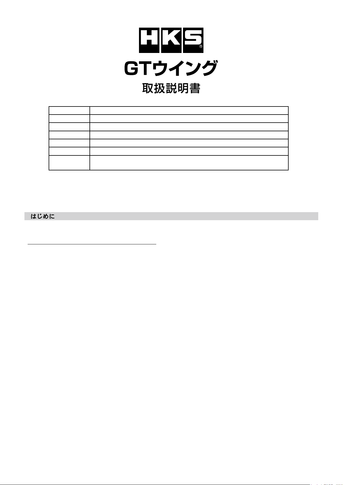
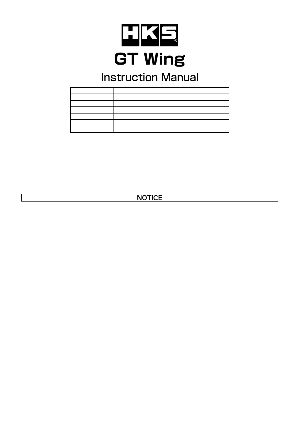
NAME OF PRODUCT GT Wing
PART NUMBER 53004-AT013
APPLICATION TOYOTA GR Supra 3BA-DB42,DB22,DB82
ENGINE B58,B48
YEAR 2019 -
REMARKS
Published in December, 2019 by HKS Co., Ltd.
(Unauthorized reproduction is strictly prohibited.)
E76111-T23010-00
This manual assumes that you have and know how to use the tools and equipment necessary to safely perform service opera-
tions on your vehicle. This manual assumes that you are familiar with typical automotive systems and basic service and repair
procedures. Do not attempt to carry out the operations shown in this manual unless these assumptions are correct. Always
have access to a factory repair manual. To avoid injury, follow the safety precautions contained in the factory service manual.
●
This manual indicates items you need to pay attention to in order to install this product safely and lists precautions to avoid
any possible damage and/or accidents.
●HKS will not be responsible for any damage caused by incorrect installation and/or use of this product.
●HKS will not be responsible for any labor expenses, related fees or losses incurred during vehicle downtime.
●This product was designed based on installing it onto a factory vehicle. The performance and/or safety cannot be guaran-
teed if this product was installed onto other inapplicable vehicles.
●
Check if your vehicle is applicable for this product.
●
If vehicle was repaired after being previously damaged in an accident, body dimensions may have slightly changed and
may cause difculties when installing this product. Check the vehicle conditions before installation.
●
Each vehicle may have a variation in gap between body parts. Temporary t the kit parts before installation and painting to
check. HKS is not responsible for any modied or painted parts and doesn’t accept return.
●
Occasional small, shallow scratches in the product surface are a result of the production process and will not affect product
nish after proper preparation and painting.
● The specications of this product are subject to be changed without notice.
●This manual is subject to be revised without notice.
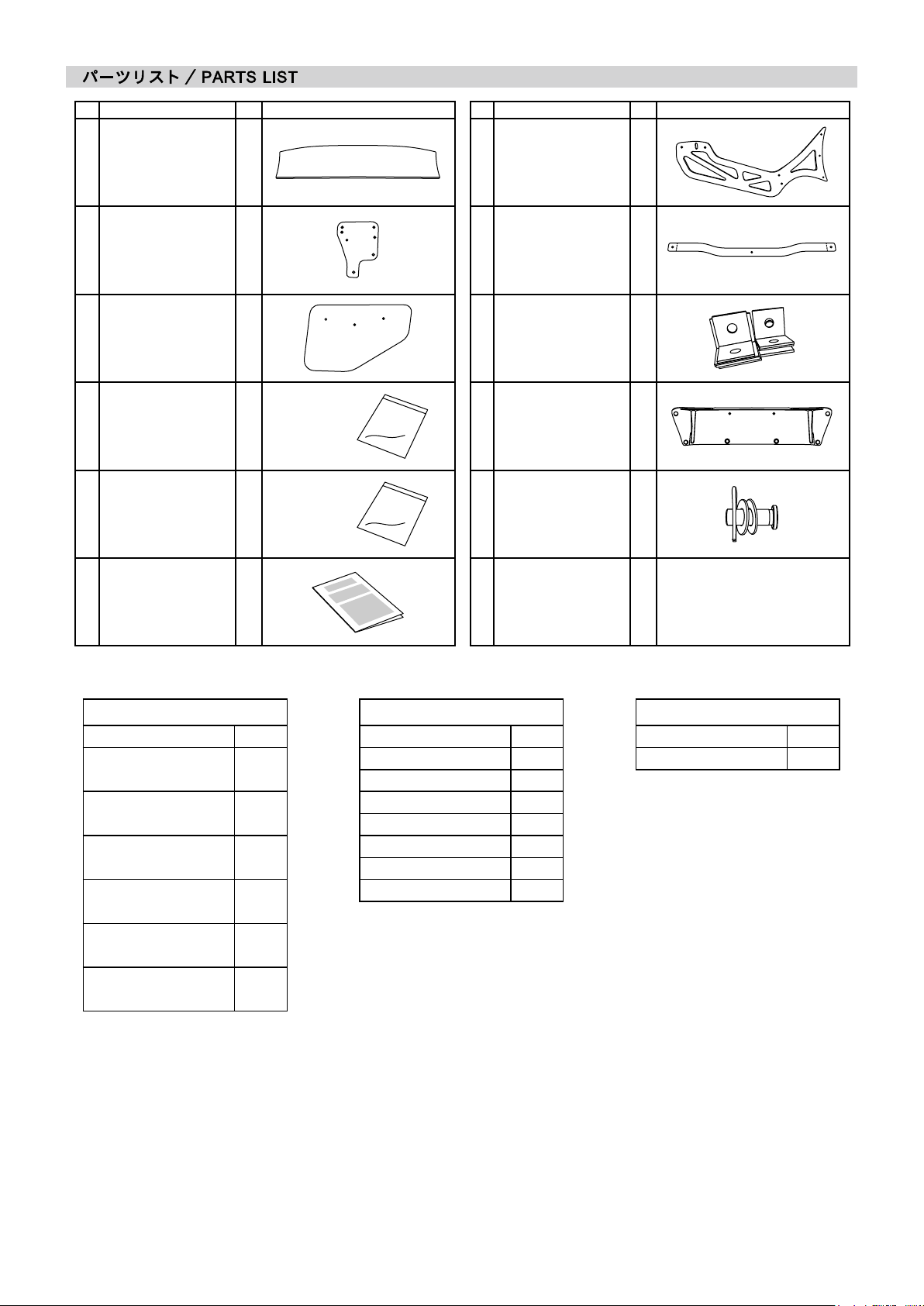
●For any lost parts, consumables or manual, please contact an Authorized HKS Dealer.
9
●HKS is not responsible for any accidents due to installation or use of this product.
●Driving on a public road for modied vehicles may be a subject to regulations.
●Installation and painting of this product should be carried out by a professional workshop.
●Installation and painting of this product requires special tools and knowledge.
●
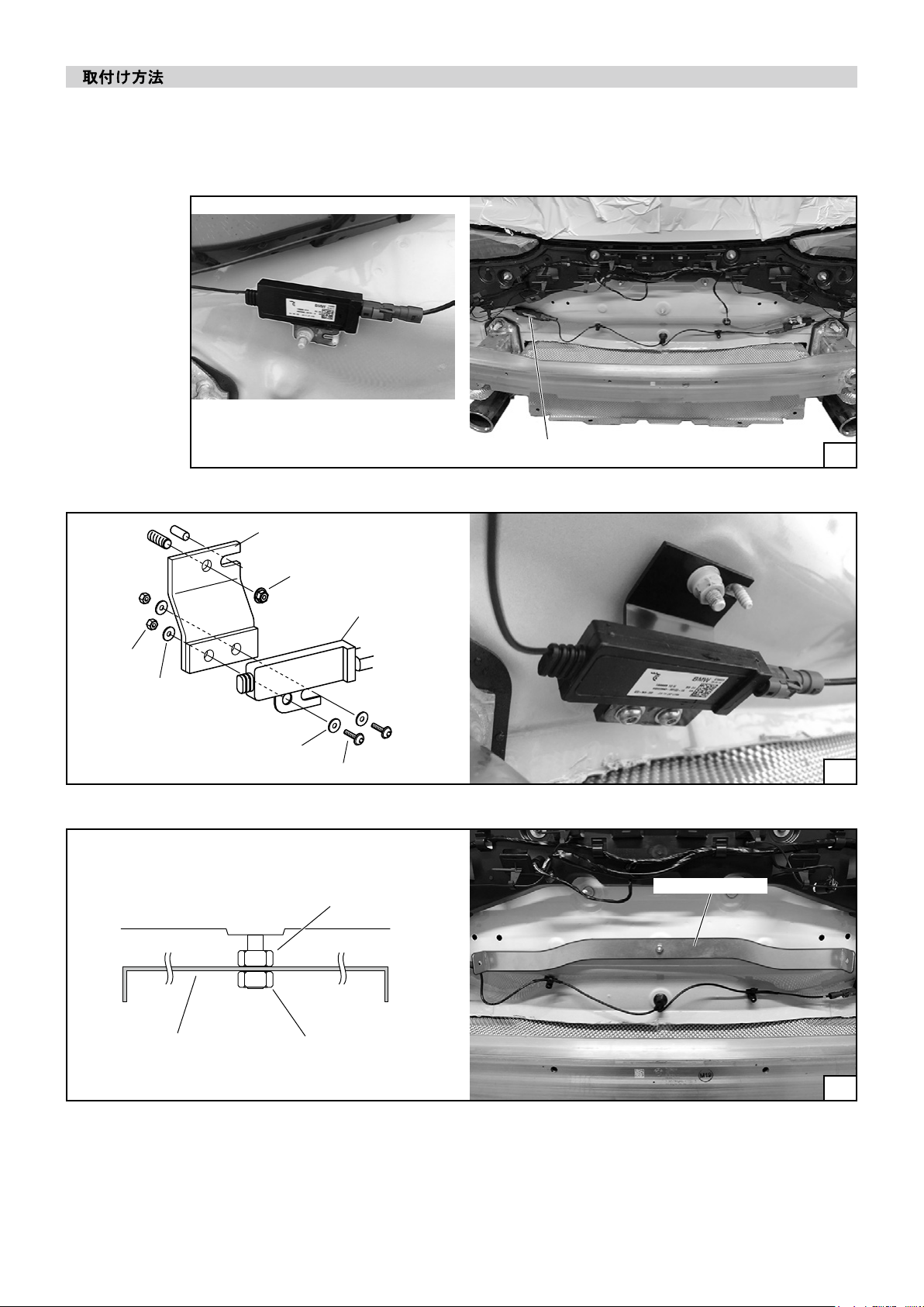
Installation of this product requires modication of vehicle body panels and product parts. Follow the provided installation
manual and perform it safely.
●Do not use any parts that are not included in this product during the installation.
●
HKS is not responsible for any accidents, damage or defect occurred due to use of parts not included in the part list of this
product.
●
Air bubbles or deformation may occur to the surface of the product under direct sunlight at temperature of 40°C/104°F and
higher, due to the product material.
53004-AT013_3-1.01

10 53004-AT013_3-1.01
● To prevent electrical damage/burns/re, always:
- Disconnect the negative terminal of the battery before beginning installation.
- When disconnecting wires/connectors, take extra care to avoid breaking/snapping the connectors.
●Do not misuse this product.
- Misuse of this product may lead to engine damage.
- Misuse of this product may lead to loss of its original function.
● This product is made of FRP. (FRP: Fiber Reinforced Plastics)
- Deformation, damage or discoloration may occur due to excessive force, impact or high heat applied.
● Modied parts of the painted surface need to be painted to prevent corrosion.
●Before securing the bolts after all the painting was done, apply the screw locking agent.
●Reinforcement of the product may be required depending on the usage conditions.
●Always wear the safety goggles and protective mask during your work.
- Make sure that all of the parts listed in the Parts List are included in the kit.
- Reference the factory service manual for the vehicle when removing factory parts.
- Be careful when handling this product; avoid dropping or subjecting it to excessive impact. Failure to do so may result in
product damage or improper installation.
- Use the proper tools when tightening nuts and bolts. If over tightened, the bolts may become damaged.
- Keep the removed factory parts in a safe place for ease of re-installation at a later date (if necessary).
When reinstalling the removed factory parts, make sure to reinstall them correctly.
PAINTING PROCEDURE
During painting follow the below instructions to prevent the cracks or breaks.
- Temporary t the kit parts before installation and painting to check. HKS is not responsible for any modied or painted
parts and doesn’t accept return.
- Prepare surface before painting. (clean and degrease, prime, paint etc.)
1) Using silicone remover or acetone to degrease the product surface from remaining wax or silicone.
2) Sand the surface, remove scratches by sandpaper (#240 to #400).
3) Degrease again by silicone remover or acetone and dry-wipe.
4) Prime.
5) After applying a primer, sand the surface again with sandpaper (#320 or higher)
- Check the pinholes on the surface and treat them if necessary.
- Dry at ambient temperatures. If forcibly drying, the temperature must be below 50°C/122°F.
- For other materials or tools, follow the instructions according to each manufacturer.
●Each vehicle may have a variation in gap between body parts. Temporary t the kit parts before installation and paint-
ing to check. HKS is not responsible for any modied or painted parts and doesn’t accept return.

(1) Disconnect the negative terminal of the vehicle’s battery.
(2) Refer to the vehicle maintenance manual and remove the rear bumper assembly.
(3) Remove the LH TV antenna cable. (Dia. 1)
(4) Relocate the TV antenna cable using the cable relocation bracket. (Dia. 2)
TV Antenna Cable
TV antenna cable (Factory)
Nut (Factory)
Cable Relocation Bracket
Nut M6
Washer M6
Gauge
Washer M6
Nut M6
Nut M6
Bolt M6-20
(5) Install the Gauge in the direction shown in Dia. 3. (Dia.3)
Gauge
Dia.1
Dia.2
Dia.3
11 53004-AT013_3-1.01

(6) Insall L Brackets to the [Wing Stay 2]. (Dia.4)
Each L bracket has a position designation.
(7) Apply to the vehicle and make sure that all L brackets are
in good contact with both the body and the reinforcement
side. (Dia. 5)
Check that the mounting angle in the vertical direction of
[Wing Stay 2] and the height of the two are equal.
ADVICE:
The width dimension of the gauge is 534mm.
Please determine the position so that the distance between
the two [Wing Stay 2] is 534mm.
(8) After conrming the position, mark the bolt hole position for
body side L brackets mounting.
(9) Drill four 9mm mounting holes in the marked part on the
body. Apply rust prevention after drilling.
A. Wing Stay 2
B. L Bracket "1"
C. L Bracket "2"
D. L Bracket "3"
E. L Bracket "4"
Reinforcement
F. Bolt M8-25
G. Washer M8
H. Nut M8
A A
D
D
G
G
G
G
G
G
G
G
G
G
G
G
B
B
E
E
H
H
H
H
H
H
C
C
F
F
F
F
F
F
Dia.4
Dia.5
12 53004-AT013_3-1.01

(10) Install the [Wing Stay 2] on the body. Fasten with the back plate inside the vehicle. (Dia. 6, 7)
A. Wing Stay 2
B. Back Plate
C. Bolt M8-25
D. Bolt M8-20
E. Washer M8
F. Nut M8
Body Body
Reinforcement Reinforcement
A A
D
D
C
C
C
CC
C
BB
E
E
E
E
E
E
E
E
E
E
E
E
E
E
E
E
F
F
F
F
F
F
F
F
Back Plate
Reinforcement
Reinforcement
Dia.6
Dia.7
Dia.8
(11) After conrming the position, mark the bolt hole position
for reinforcement side L brackets mounting.
(12) Drill four 9mm mounting holes in the marked part on the
reinforcement. (Dia. 8)
(13) Drill four 18mm service holes on the outer side of the
Reinforce vehicle. (Dia. 8)
13 53004-AT013_3-1.01

Make holes
Wing Stay 1
Wing Stay 2
Wing Stay 1
(14) Install the [Wing Stay 2] to the reinforcement. (Dia. 6, 8)
(15) Remove the gauge.
(16) Make holes in the rear bumper assembly so that the [Wing
Stay 2] passes. (Dia.9)
(17) Reinstall the rear bumper assembly and the license plate.
(18) If necessary, such as when drilling has failed, attach the
[Rear Bumper Cover] to the rear bumper assembly using
M4 screws.
(19) Install the [Wing Stay 1]. (Dia.10)
Install the [Wing Stay 1] on the outside of the [Wing Stay 2].
This picture shows a typical hole’s position.
Actual position may vary depending on the vehicle.
Wing Stay 2
Bolt M8-25
Bolt M8-25
Pin
Washer M8
Washer M8
Washer M8
Washer M8
Nut M8
Nut M8
(20) Install the [Rear Wing] to [Wing Stay 1] using bolt M6-20
and washer M6. (Dia. 11)
(21) Install two [Wing End Plate] to the [Rear Wing] using bolt
M6-20 and washer M6. (Dia. 12)
(22) Reconnect the negative terminal to the vehicle’s battery.
Wing Stay 1
Wing End Plate
Rear Wing
14 53004-AT013_3-1.01
Dia.9
Dia.10
Dia.11
Dia.12

Proper daily maintenance of this product is necessary in order to maintain the safety, reliability, and function of this product.
Maintenance is the responsibility of the driver/owner.
- If work needs to be performed outside the scope of this manual, consult a professional.
- If the vehicle becomes damaged, have the repairs performed by a professional.
- If you experience abnormal noises, scents, or vibrations from the vehicle while driving, reference the vehicle’s Owner’s Manual.
- If this product is ever sold, please give this Instruction Manual to the new owner.
- When removing this product from the vehicle, please consult a professional.
- Avoid using an automatic car wash.
- For cleaning and care for this product, a wax coating is required same as for the body surface. Do not use a thinner which con-
tains the organic solvent or polishing compound.
- Regularly check if the bolts and nuts are secured rmly.
- Remove this product immediately if the product was damaged or deformed by accident or accidental contact.
- Air bubbles or deformation may occur to the surface of the product under direct sunlight at temperature of 40°C/104°F and
higher, due to the product material.
15 53004-AT013_3-1.01
This manual suits for next models
1
Table of contents