HM Machinery SBM 28B User manual
Industrivej 3-9
9460 Brovst,
Denmark
Tel. + 45 98236088
Fax. + 45 98236144
MANUAL
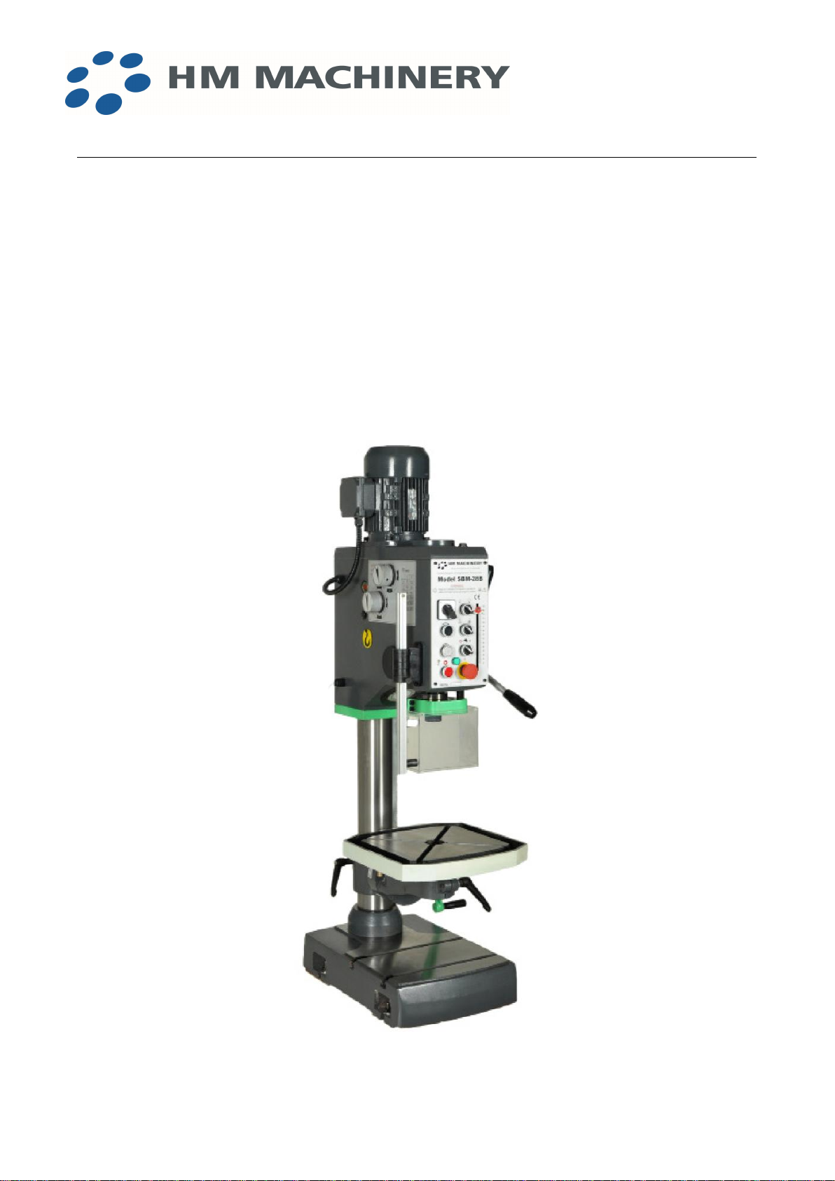
GEARED HEAD DRILLING MACHINE
HM SBM 28B

EU declaration of conformity
HM MACHINERY A/S
Industrivej 3-9
9460 Brovst
DENMARK
Tlf.: + 45 98 23 60 88
Fax.:+ 45 98 23 61 44
hereby declares that
HM SBM-28F are manufactured in accordance with the provisions of the European
Parliament and Council Directive 2006/42 / EC of 17 May 2006
And also in accordance with:
·Low Voltage
·EUROPEAN PARLIAMENTAND COUNCIL DIRECTIVE 2014/35 / EU of 26
February 2014
·EMC
·EUROPEAN PARLIAMENT AND COUNCIL DIRECTIVE 2014/30 / EU of
26 February 2014

Vigtigt
Husk påfyldning af olie inden opstart
Important
Remember to fill oil in the gearbox before use of the machine.
Achtung
Bitte Öl auffüllen bevor die Maschine gestartet wird
Important
S'il vous plaît n'oubliez pas de mettre de l'huile dans
la boîte de vitesses avant d'utiliser la machine.
Importante

Recordar rellenar con aceite la caja de transmision antes de arrancar la maquina.
CONTENTS
1. NOTE
2. PASSPORT DATA
3. LIMITED WARRANTY
4. SAFETY AND GENERAL INFORMATION
ªSAFETY
ªFORESEEN USE OF THE MACHINE
ªCORRECT USE OF THE MACHINE
ªPIECE CLAMPING
ªTOOL FIXING
ªCHIPS DURING MACHINE
5. TEST REPORT
6. MAIN SPECIFICATIONS
7. INSPECTION
8. CLEANING
9. INSTALLATION
10.MACHINE OPERATION INSTRUTION
11.UNLOAD TOOL OPERATION MANUAL
12.SPEED LEVER PANEL
13.WIRING DIAGRAM
14.DRILL PROTECTON GUARD
15.ELECTRIC CONNECTION
16.MACHINE CARE AND MAINTENANCE

NOTE
This manual has been prepared for the owner and operators of this machine. Its purpose,
aside from machine operation, is to promote safety through the use of accepted correct
operation and maintenance procedures. Completely read the safety and maintenance
instructions before operation or servicing the machine. To obtain maximum life and
efficiency form your machine, and to aid in using the machine safety, read this manual.
Since we continually strive to incorporate latest developments in the construction of the
machine, it is quite possible at time, due to printing and shipping requirements, some data
may not correspond to the machine in question.

LIMITED WARRANTY
We make every effort to assure that our products meet high quality and durability
standards and warrants to the original retail consumer/purchaser of our products that each
product be free from defects in materials and workmanship as follow: ONE YEAR LIMITED
WARRANTY ON ALL PRODUCTS UNLESS SPECIFIED OTHERWISE. This warranty
does not apply to defects due directly or indirectly to misuse, abuse ,negligence or
accidents, normal wear and tear or alterations outside our facilities, or to a lack of
maintenance.
We shall in no event be liable for death, injuries to persons orfor incidental, contingent,
special, or consequential damages arising from the use of our products.
To take advantage of this warranty, the product or part must be returned for examination,
postage prepaid. Proof of purchase date and an explanation of the complaint must
accompany the merchandise. If our inspection discloses a defect, we will either replace the
product, or refund the purchase price,if we cannot readily and quickly provide a repair or
replacement. We will return repaired product or replacement at our expense, but if it is
determined there isno defect, or that the defect resulted from causes not within the scope
of our warranty, then the user must bear the cost of storing and returning the product.

SAFETY AND GENERAL INFORMATION
1. SAFETY
A drilling machine, due to its purpose, is considered an “open machine” Therefore, some
safety measures have to be taken to avoid accidents.
Bear in mind the following safety instructions:
FThe machine must always be operated for the purpose for which it was designed.
FDo not ever stand under a hanging machine or nearby, when it is being loaded for
transportation.
FConnect the machine to an exclusive electric connection, which includes differential
switch of protection. First plug in the green-yellow protection wire and then the others.
FThe piece must always be fastened with suitable devices. Do not ever handhold the
workpieces.
FSharpened tools in good condition must always be used.
FAppropriate tools must always be used, Do not ever adapt a tool for a use for which it
was not designed.
FUse the correct speeds and feeds for the material being machined as well as for the
tool being used.
FUse glasses to prevent small chips from getting into the eyes.
FInsert the tools correctly in the tool holder cone.
FFix the work piece fastening devices to the machine table.
FDo not wear baggy clothes, loose gloves, etc, which can be caught by the tool while
drilling.
FKeep the working place clean.
FGather the chips with suitable instruments (brush, gloves, etc.)
Before carrying out any operation which is not strictly drilling,

Ftapping etc. (like lubricating, changing of tools, etc,) turn the main switch to the
“0”position.
FBefore changing speeds, stop the machine and wait until all moving elements are
completely brought to a halt.
FDo not ever leave the machine on without supervision. When leaving the machine,
check that the general switch is in the “0”position and that moving elements are
stopped.
FCheck periodically the correct operating of all security controls and elements of the
machine.
FBefore pressing the starting pushbutton, set the drill protector guard in the working
position.
FConsider work area environment. Don’t use electric power driven tools in damp or wet
locations. Keep work area well lit. Don’t use electric power tools in presence of
flammable liquids or gases.
FKeep children away.
FUse only such accessories and attachments as are recommended in the operating
instructions or the catalogue for the power tool concerned.
2. FORESEEN USE OF THE MACHINE
The drilling machine was designed to be used with specific tools and for certain machining
operations.
The most common machining operation is the drilling of holes with helicoidal drills. The
drilling of holes is carried out by the combination of a drill turning movement and a feed
movement in the turning spindle direction.
Besides the helicoidal drill, other tools can be used to drill holes. There is a great variety of
drill types and shapes in the market,which can be used on this machine, provided that
they are designed for such a purpose and that can be fixed in the spindle

taper. They will usually be the Morse taper or ISO type. The drill shanks should have the
corresponding taper to the spindle in which they are to be fitted, or parallel shank if they
are going to be fitted by means of a tool holder. Contact the tool manufacturer for any
further information. Do not ever use tools which were not designed to be used in a drilling
machine.
A drilling machine can also perform other machining operations apart from the drilling,
such as tapping, reaming, chamfering, punch marking, countersinking, spot facing. To
perform such operations, it is necessary to have appropriate tools, specially designed for
this sort of jobs. In the tapping case, besides using correct tool, the machine has to be
provided with such a device that verses the turning direction of the tool when it reaches the
depth previously fixed.
3. CORRECT USE OF THE MACHINE
FNot exceeding its working capacity.
FOperating the machine by qualified and trained staff,and according to the points
mentioned in the instruction book.
FWorking under the safety systems provided with the machine, checking them and
keeping them.
FWatching the safety measures mentioned in the instruction book and notices on the
machine.
FWearing clothes which provide personal safety as mentioned in the instruction book.
FWatching the safety measures which may affect work on the machine,and that can be
lawfully expected, as well as those demanded in the workshops.
4. PIECE CLAMPING.
Tangential cutting forces and axial forces in the feed direction of the tool are mainly
produced during the drilling process. The tangential forces produce a moment of forces
which make the piece being drilled turn. Therefore, the pieces to be drilled (or to be
machined by one of the operations mentioned above) must be clamped in an appropriate
device, such as a drill chuck, and the drill chuck must be correctly clamped to the machine
table. For this reason the machine tables are provided with “T” slots.
The pieces must be clamped conveniently by some clamping device.

The clamping devices must be clamped to the machine table.
The machine table is provided with “T” slots for such purpose.
5. TOOL FIXING
The tools generally used in this machine will have parallel or taper shanks. Drill holders
are normally used to fix the main spindle of the machine to the parallel shank tools. This
fixing device is used for small drill diameters (max. up to dia.16mm). Bigger diameter drills,
usually have taper shank of Morse taper (the ones of smaller diameters than 16mm can
also have taper shanks).
The housing in the main spindle to insert the tool is of Morse taper type. It is very important
to insert the tool taper correctly in the main spindle taper to avoid the tool falling from its
housing when turning and provoke an accident. The coupling system itself of the tool male
taper in the female taper of the main spindle is auto-locking, but for it to work the surfaces
of the tool taper and spindle taper must be in contact. To get the best possible contact, the
surfaces of the tool taper as well as the spindle taper should be in good conditions.
Therefore, it is advisable to handle the tool as well as the spindle of the machine carefully.
6. CHIPS DURING MACHINE
The machining process removes material from the piece. This material is released in
chips, which can be of different shapes depending on the material itself. The most
common ones are of three types: fragmented chips in small bits, short helicoidal chips and
long helicoidal chips.
The chips fragmented in small bits can be rejected from the machining area and can be
dangerous if they reach the eyes of the operator. To avoid this, it is advisable to wear
safety glasses.
The long helicoidal chips tend to roll up the tool and gain considerable volume before
breaking, which is dangerous if they reach the operator,as they may produce injuries.
The reached volume may also displace the drill protector from its security position,
increasing the risk of an accident. It is advisable to use chip breaking tools to machine
materials which produce such chips. For further information contact the tool manufacturer.

TEST REPORT
No. Checking items Inspection item Tolerance Data
G1 Flatness of table and
base
0.12
G2 Spindle taper run out
a. At the end of
spindle nose
b. At the end of
200mm test bar
a.0.03
b.0.06
G3 Verticality of spindle
center line to table
a. Transverse direction
b. Longitudinal
direction
a.0.10/300
(α≤90°)
b.0.10/300
G4 Verticality of spindle
sleeve vertical travel to
table
a. Transverse direction
b. Longitudinal
direction
a.0.10/150
(α≤90°)
b.0.10/150

MAIN SPECIFICATIONS
Model GB 28 S
Max.drilling capacity mm 28
Spindle taper —MT3
Spindle stroke mm 130
Distance from spindle center to column surface
mm 250
Distance from spindle nose to worktable
mm 125-825
Distance from spindle nose to base mm 1220
Spindle speeds range rpm 75-3200
Number of speeds —12
Diameter of column mm 98
Worktable size mm 380×380
Dimensions of base mm 360×535
Width of T-slot mm 14
Distance of T-slot base mm 160
Main motor(2 speed motor)KW 0.85/1.1
Packing size(L×W×H) mm 2100×400×640
N.W/G.W KG 200/230
20'container Q'ty: sets 42
Transport
Insert an iron bar through the transversal hole in the machine head which with the aid of a
rope, will be used for lifting the machine.

INSPECTION
The machine should be carefully examined on arrival, to check that it is complete and in
good order, so that claims can be made, if necessary.
CLEANING
Remove all anti-rust compounds. Clean and lubricate all movable parts.
INSTALLATION
In order to guarantee the stable working of the machine.
Please tighten the foundation bolts before operating.
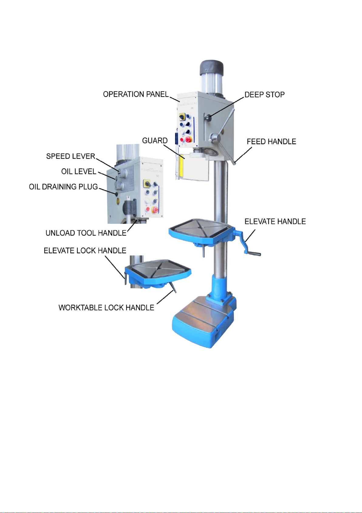
MACHINE OPERATION INSTRUCTION
FIG.1

Table elevation
LoosenLOCK HANDLE, turning TABLE ELEVATE HANDLE, the table elevates vertically.
Fix the LOCK HANDLE when you reach the requested working position.
Table rotation
Loosenthe LOCK HANDLE, pull the table left or right to move around the axis of the
column. Fix the LOCK HANDLE when you reach the requested position.
Table turning
Loosenthe TABLE LOCK BOLT, pull the table up and down, fix the TABLE LOCK BOLT
after turning to the requested angle.
Inclined hole processing can be realized.
Spindle elevation
Press down the FEED HANDLE, spindle going down.
Tools installation and disassembling
Fig.2
OFF
ON

UNLOAD TOOL OPERATION MANUAL
1. According to the Fig.2, please pull out the UNLOAD TOOL HANDLE.
2. First the left hand should hold the tool, then the right hand push upward the FEED
HANDLE.
ATTENTION:
When using should put the handle in “OFF” position.
CAUTION: Tools installation and disassembling should be performed after machine is completely
stop running.
CAUTION: When installing and disassembling the tools, the emergency stop switch should be
pressed down.
Open the safety guard, install the tools in the spindle hole, make sure it is fixed
installing.
NOTE: Close the safety guard, loose the emergency stop switch then running machine.

SPEED LEVER PANEL

WIRING DIAGRAM

ELECTRIC COMPONENTS LIST
Code Name Model Specification Qty
HK Main switch JCH13-20/3
HZ Double speed
switch
3LBB-20 1
KM1-2 Contactor 3TB41-22
Coil voltage 24V
1
TC Transformer JBK5-63 1
SQ1 Microswitch LXW16-16/1C2 1
SQ2 Microswitch LXW16-16/1C2 1
HL SC-108E 24V,35W 1
SL Power indicator light
AD17-16 AC24V
1
SB1 Mushroom button YO90-01M 1
SB2,SB3 Button + pilot lamp
YO90-22 2
SA1 Switch YO90-20XB/3 1
SA2 Switch YO90-20XB/2 1
FU1 Circuit Breaker DZ47-63 D1 1P 1
M1 Main motor YD100L-8/4 0.85/1.5KW 1
Table of contents
Languages:
Other HM Machinery Drill manuals


