Hogtunes NCA 450U Kit-RM User manual

NCA 450U Kit-RM
High Performance Front & Rear Speaker Kit with 200 Watt Amplifier
For Use on 1998-2013 Ultra ClassiCs and tri‐Glides
installation Manual
NCA 450U Kit-RM
High Performance Front & Rear Speaker Kit with 200 Watt Amplifier
For Use on rUshmore platForm models
installation Manual

2
Thank you for choosing the Hogtunes REV 450U KIT-RM speaker and amplifier
kit for “Rushmore” platform Ultra Classics. Since positive word of mouth is the
best way to grow our business, we want your new system to work as well as it
was designed to. If you have any questions or concerns, we are here to help.
The installation will be done in 3 major steps.
Step 1: Changing out the Front speakers
Step 2: Changing out the Rear speakers
Step 3: Installation of the amplifier
Please identify the two pairs of speakers now. Model 362F-RM (with larger
magnets) are for the front and 362R-RM (smaller magnets) are for the rear.
The rear speakers will fit in the front location but the front speakers will NOT
fit in the rear location. If you do not identify the speakers now, there is a
serious chance wrenches and expletives will be flying soon!
Hogtunes Contact Information
Tel: 705-719-6361
A video version of this manual is available at
www.hogtunes.com If you still need
assistance, please consider a professional
installation by your motorcycle dealer.

3
362F-RM FRONT SPEAKER
INSTALLATION INSTRUCTIONS
Step #1: Remove the seat and both wires (+ and -) from the battery. Remove the
outer fairing/headlamp assembly and set aside. Refer to a service
manual if you need help with this. NOTE: Placing a towel on the front
fender can help prevent scratches or “dings” from dropped tools or
fasteners, etc. Expletives will also be kept to a minimum!
Step #2: Speaker Cabinet Removal: On the brake side speaker cabinet,
carefully remove the cable going into the power port/cigarette lighter
assembly. If your bike has the CB module (mounted “sideways” on the
clutch side cabinet) undo the antenna cable and main harness. The
CB Module will stay attached to the clutch side cabinet when removed.
Undo the speaker wire plugs going into each cabinet (pink/pink with
black stripe wires).
The speaker cabinets are vital to the fairing’s structure.
DO NOT operate the bike without the speaker cabinets installed!
NOTE: We STRONGLY suggest completing the speaker swap on one side and
then moving to other side! Figure 1.1 and 1.2 (below) have arrows that point
to the factory fasteners that will be removed to allow the cabinets to come
out of the bike. Although the Brake Side is shown below, fastener locations
are common for both brake and clutch side cabinets.
Figure 1.1
Side view of brake side cabinet
Figure 1.2
Back view of brake side cabinet

4
Step #3: Installing the new speaker: With the cabinet removed from bike,
undo the four screws that hold the factory speaker to the cabinet.
Carefully take off each speaker wire by disconnecting one at a time.
Take a Hogtunes speaker and re-attach the factory speaker wires noting
they will only go on one way. Make sure to use the model 362F-RM
speakers (with larger magnets) for the fronts! The #1 reason for tech
related calls is loose wires at the speaker which is why we designed the
self-locking clips on the speaker frame. Using the factory screws, attach
the Hogtunes speaker to the cabinet noting that there is a locator “peg”
on the cabinet and a hole in the speaker’s frame which needs to line up
so the speaker sits flush to the cabinet. Bass response will be greatly re-
duced if the speaker is not flush to the cabinet! The factory speaker grill
must be removed and replaced with the supplied metal mesh grill using
the three factory screws on the inside of the fairing. On the factory grill,
you will see two round holes and one “keyhole” where the screws go
through and into the fairing. The keyhole on our grill needs to go in
the same spot for proper fitment of the new grill! With the new grills in
place and the speaker properly attached to the speaker cabinet, the
cabinet can be re-installed to the bike. It’s always a good idea to put the
factory fasteners back in to specified torque.
Repeat Step #3 for the second cabinet. Make sure to plug the power
cable back into the power port/cigarette lighter assembly on the brake
side. If your bike has the CB module, make sure to re-install the antenna
cable and main harness.

5
362R-RM REAR SPEAKER
INSTALLATION INSTRUCTIONS
Step #1: Remove the factory speaker grills by undoing the four screws on the front
of the grills. Carefully lift up on each speaker and take the two wires off
by pulling one at a time from the stock speaker. Remove the speakers.
Step #2: Hogtunes 362R-RM rear speakers are a direct replacement for the
OE speakers. The female OE “in-line” connectors mate with the male
connectors on each speaker and only go on one way. The #1 reason
for tech support calls is due to loose connections at the speaker. Please
make sure you have a very good connection to avoid this. Once you
are confident the factory wires are correctly attached to the new speak-
ers, set them in place, install the grills that came with the kit and secure
the speaker by re-installing the four screws per grill. NOTE: The factory
rubber “nutserts” on the rear pod side can be finicky. It’s a good idea to
get all four grill screws “started” and then get each one snug. Gradually
tighten each one down making sure all four screws holding
the grill down are secure!

6
NCA 450-RM AMPLIFIER
INSTALLATION INSTRUCTIONS
Step #1: Over top of the radio, pull up to release each wire harness from the
black plate via the factory “Christmas Tree” fasteners. If your bike has
factory GPS, the small square antenna will need to be relocated just
behind the voltmeter as shown in Fig 1.1 below. Remove the four factory
T-20 “Torx” screws that go through the top of the black plate and into
the top of the radio.
Step #2:
Step #3: The amplifier comes pre-mounted to a silver mounting plate. Locate and
remove the four screws (2 per side) that attach the amp to the silver plate.
Put these screws (just removed) and the amplifier aside for now.
Step #4: Sit the supplied silver plate on top of the radio so it is oriented as shown
in Fig 1.2 on the next page. Locate one of the supplied “star” washers
on each factory screw and re-install the screw/washer through the silver
plate, through the factory black plate and into the top of the radio. Locate
the main power harness and plug it into the matching “pig-tail” on the
side of the amp. The rear wire harness is the longest in your kit. Locate
this harness and plug the one end into the mating 8 pin pigtail coming
out of the amp. Sit the amp on top of the silver plate so when standing
in front of the bike you can read the Hogtunes logo on top of the amp.
On the side of the amp, you will see a switch labeled “fader/no fader.”
Make sure this switch is on “fader.” Re-install the amp to the plate using
the four screws removed earlier.
Figure 1.1 - The white
circle shows the new
location for GPS
Antenna if your bike
came factory equipped
with this feature.

7
Step #4: Figure 1.2
shown here.
Step #5: Also in Fig 1.2 is a white square which shows a smaller black 2 pin
factory plug. The orange wire from the amp has a plug that goes
directly into this factory harness. On the factory plug we are describing,
there maybe a factory plug with no wires already installed into it which
will have to be removed. The factory wire colors going into the plug
are purple/blue stripe and black and can be see under the factory
sheathing. The orange wire is the amplifier’s “turn on” lead and tells the
amp to turn on/off with the bike’s ignition. The amplifier will not turn on
if this wire is not hooked up to this (or any) switched B+ source!
Step #6: On the amp, you will see a wire sheath containing blue/black and
green/black wires with two plugs. The plug with the blue/black wires
will install into the factory plug that goes directly into the brake side
speaker cabinet. The plug with green/black wires will install into the
factory connector that originally plugged directly into the brake side
speaker cabinet (has pink/pink with black stripe wires).
Step #7: On the amp, you will see a second sheath with brown/black and
yellow/black wires and two plugs. The plug with the brown/black wires
will install into the factory plug that goes directly into the clutch side
speaker cabinet. The plug with yellow/black wires will install into the
factory connector that originally plugged directly into the clutch side
speaker cabinet (has pink/pink with black stripe wires).
Figure 1.2 - Amplifier and mounting plate
correctly oriented. The plate with four small
holes is for mounting a popular Harley
accessory. The white circles show tabs which
are there for the “Christmas Tree” fasteners to
re-secure the harnesses lifted earlier.

8
ROUTING THE POWER
AND REAR SPEAKER HARNESS
Step #1: The power/ground harness and rear harness will pass together under the
inner fairing where the main wire harness passes through on the brake
side of the bike. Loosen the tank’s “chrome console” and run wires up
and over the gas tank, but under the tank’s chrome console. There is a
provision on the front of the tank console for wires to pass.
NOTE: Although not necessary, the power and rear harnesses can go
under the gas tank if you choose to remove and re-install the tank.
•Whencorrectlyinstalled,thepowerandgroundwiresaretheright
length to connect to the battery. The supplied rear harness for Ultras is
the right length so that its two ends can sit on the middle of the back
fender just behind the threaded insert for the bolt that holds the back of
your seat in place.
Step #2: Just behind the threaded insert that holds the seat bolt on the back fender,
you will see a large factory wire plug. One side of the plug has wires that
go to each rear speaker pod. Separate this large factory plug. One plug
from the Hogtunes rear harness will plug into each side of the factory
plug just separated. They will only go together one way.
At this point, all audio connections for this system are made. You will
have a left over plug on the amp with four wires (red/black and white/
black) and is what we call the bypass harness. Although this plug is not
used as part of this system, it is there for future expansion of your system
as we release more products for Rushmore platform bikes.
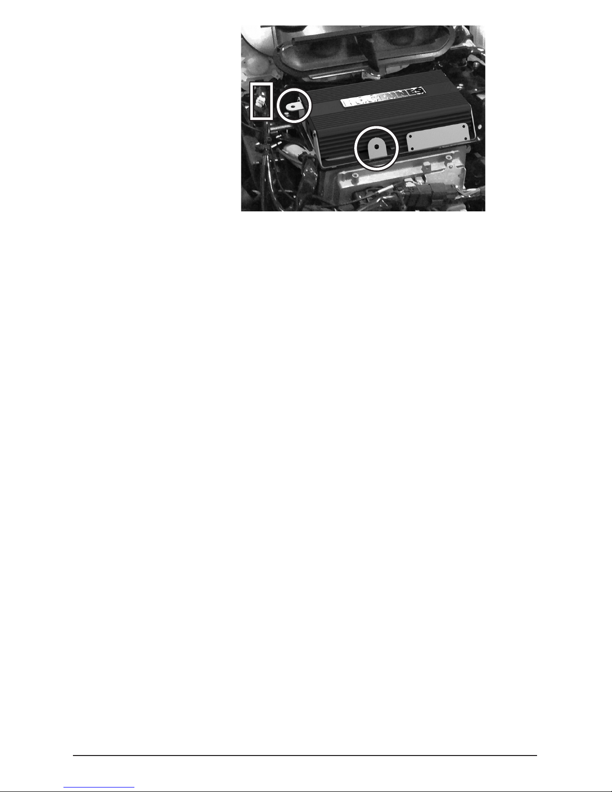
Stock Harness and Amplifier’s
Harnesses Passing From Fairing
To Just In Front Of Tank
(Arrow A) . Cable Tying the
Harnesses To The Main Bike
Harness Just In Front Of The
Tank (Arrow B) Allows The Amp
Harnesses To Go Up Towards
The Tanks Chrome Console
Easier And Makes For a
Cleaner Install.
A
BBA

9
Step #3: Next to the “fader/no fader” switch is a 3 position switch to adjust the
rear channel volume. On Ultra Classics, we use the bike’s built in fader
control to allow you to adjust the front/rear volume from the radio itself.
For best performance, this switch needs to be left in the +3 position.
Step #4: Attach the amp’s red wire to the positive (+) battery terminal and the
amp’s black wire to the negative (-) battery terminal. The factory battery
wires are also re-installed at this point. When attaching the power and
ground wires, it is always a good practice to do the negative first.
When the positive connector touches the battery, some sparking is
normal. This is a function of the capacitors in the amplifier charging up.
Step #5: Turn the stereo on and, at low volume, test to make sure all four
speakers are working. Make sure the radio’s fader control is adjusting
the volume between front and rear speakers. If not, double check the
“Fader/No Fader” switch.
Step #6: Re-install the seat making sure the amplifier’s “+” and “-” connectors are
positioned in such a way so they will not bend or break when the rider’s
weight is on the seat.
This is the best time to take a few minutes to “clean up” the wiring
and secure using supplied zip-ties.
Before re-installing outer fairing, turn front wheel
to each extreme side making sure any wiring is
not impeding the steering of the motorcycle.
Failure to do so can result in serious
injury or death!
Re-install the fairing and your system is now ready to enjoy!

10
adjusting Your sYsteM-Please read!
In order to make your new system perform as good as it was designed,
please take a minute to understand and follow these tips:
1) Set your “Automatic Volume Control” (AVC) to 3 bars. After extensive
on-road testing, we found that this AVC position works and sounds best.
Your new amplifier has been specifically set-up for this radio setting.
2) Your Hogtunes system is designed specifically for a motorcycle at speed.
Exhaust noise and wind noise have been taken into careful consideration
in how your system performs. How your new system sounds in a driveway
or garage is radically different from how it will sound at highway speeds.
Although your system was set-up with a factory radio, with its bass and
treble controls in the middle position, if you feel the need to make
adjustments please do so (carefully) at your normal cruising speed.
technical sPecifications
Hogtunes NCA 450U Kit-RM
Amp’s RMS Power at 2 Ohms: 50 Watts x 4 Channels
Speakers: 125 Watts RMS 200 Peak
Frequency Response: 40hz - 25khz
Fuse at Amp: 30 amp

11
Harley-Davidson, Electra Glide, Road Glide, Street Glide, Ultra Classic, Tri Glide, CVO, Screamin
Eagle and Tour-Pak® are Trademarks, and/or Registered Trademarks of Harley-Davidson, Inc.,
Milwaukee, Wisconsin, USA, and if Used or Implied are for Reference Only. There is No Affiliation
Between Harley-Davidson, Inc., and Hogtunes Inc.
WarrantY inforMation
Please Record Your Amplifier’s Serial # Here_________________________
Hogtunes speakers are warranted for a period of 20 years. The NCA 450-RM
Amplifier is warranted for 3 years from original purchase date. Proof of purchase
is required for all warranty claims. The warranty applies to the original retail
customer and is not transferable. Please contact Hogtunes for all warranty claims.
Products found to be defective during the warranty period will be repaired or
replaced (with a product deemed to be equivalent) at Hogtunes sole discretion.
Hogtunes complete warranty policy is available on our website at:
www.hogtunes.com/warranty.html
What Is Not Covered:
1) Any expense related to the removal or re-installation of Hogtunes products.
2) Repairs to these products performed by anyone other than Hogtunes.
3) Subsequent damage to any other components.
4) Any product purchased from a non-authorized Hogtunes dealer.
5) Damage to Hogtunes products due to an accident or collision.
6) Hogtunes Amplifiers with broken or removed “warranty void” stickers.
7) Damage due to water from custom installations.
8) Damage from incorrect installation, improper use, abuse or modifications.
9) Damage to inbound product due to improper packing.
IMPORTANT: In the event of a warranty claim, please fill out the
form in the Warranty section of our website, or contact us by
email or by phone. Valid claims will have a Return Authorization
Number (RA#) generated which MUST appear on the outside of
the box when it arrives to our office.
Goods Arriving Without an RA# Will Be Refused!

Any audio system can be a
distraction to the rider
and/or passenger. Please
use caution when
playing your stereo,
ESPECIALLY IN TRAFFIC.
www.hogtunes.com
Table of contents
Other Hogtunes Car Speakers manuals