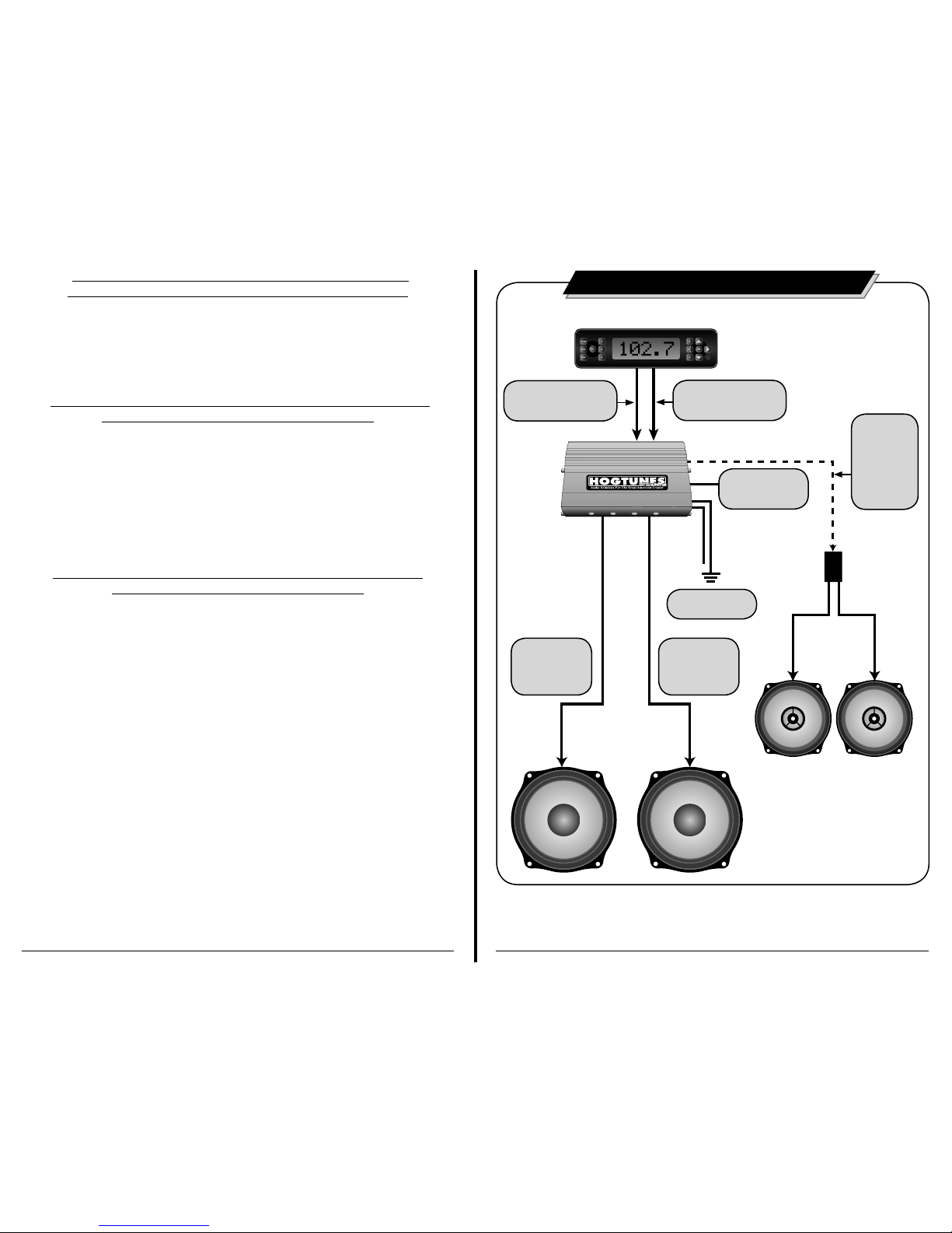
AMPLIFIER WIRE COLOR CODES
YELLOW/BLACK: Clutch Side Amplifier Input From Factory Radio
BROWN/BLACK: Clutch Side Radio Power Output to Front Speaker
GREEN/BLACK: Brake Side Amplifier Input From Factory Radio
RED/BLACK: Brake Side Radio Power Output to Front Speaker
BROWN/BLACK: Amplified Output to Clutch Side Lower Speaker
BLUE/BLACK: Amplified Output to Brake Side Lower Speaker
ORANGE: Remote Turn On Lead
RED: 12v Positive--Attaches Directly to “+” Battery Post
BLACK: 12v Negative--Attaches Directly to “-” Battery Post
WIRING THE AMPLIFIER
Step #1: Plug the 2 connectors of the main wire harness into “Power” and “Audio
Input” on the amplifier. Tighten (snug) the 2 small flathead screws on the
power connector to prevent it from backing out while riding.
Step #2: On the input harness, locate the yellow/black pair of wires with the
male connectors and plug them into the factory speaker wires on the
clutch side of the bike. Also on the input harness, locate the green/
black pair of wires with the male connectors and plug them into the
factory speaker wires on the brake side of the bike. The connectors are
sized correctly, and will only go in one way.
Step #3: Locate the wire harness with the blue plug and white/black, and red
black wires on it, and plug it into the blue plug which is part of the input
harness you just installed into the amp. Take the white/black wires and
connect them directly to the clutch side main fairing speaker. Take the
red/black wires and connect them directly to the brake side speaker.
Step #4: On the opposite side of the amp are 3” (75mm) wires ending with a 4
pin black connector. This plug sends amplified power to your speakers.
Locate the 4 pin black plug wire harness with brown/black and blue/
black wires, and plug it into the amplified output plug. If not already
installed, plug the wires that will go into your lowers marked clutch side
and brake side into the open end of the harness you just plugged into
the amplified output plug.
7
Step #5: The orange wire is the “remote turn on lead” and tells the amp to turn on
whenever it sees +12v (.5 amp min.). Unplug the factory center wire (+)
on the cigarette lighter. Plug the orange lead from the amplifier directly
onto the lighter using the female connector. Plug the factory lighter wire
to the male “take off” connector which is part of the amps orange turn
on lead. Important: If you do not attach the orange wire from the amp
to the center wire at the cigarette lighter, the amplifier will not turn on.
If the factory fuse for your cigarette lighter is blown, and your cigarette
lighter does not work, your amplifier will not turn on.
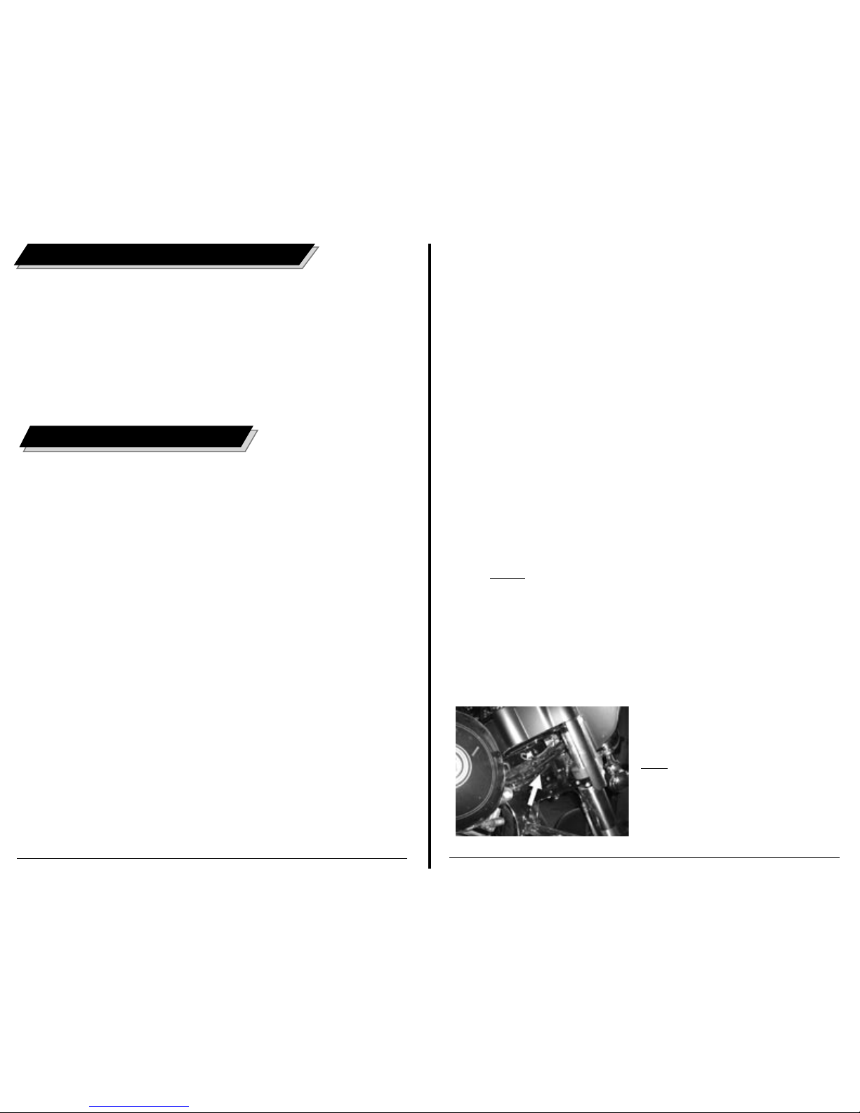
Step #6: The red (B+) and black wires (B-), and the speaker wires marked “Clutch
Side” and “Brake Side” of the main wire harness will pass under the
inner fairing where the throttle and idle and/or bikes main wire harness
pass through on the brake side of the bike. Let the Clutch Side and Brake
Side wires hang on the front side of the crash bar for now. The red and
black wires are designed to be routed under the gas tank and across
the motor mount on the brake side of the bike, and come out just behind
the gas tank. You may need to undo the back bolt of the gas tank and
pivot the tank up to allow the harness to pass through at the back of the
gas tank. Be sure to re-install this bolt and torque to factory specs! When
correctly installed, the power and ground wires are the right length to
connect onto the battery.
NOTE: on ‘07 and newer bikes it is much easier to run
power and ground wires up and over the gas tank,
but under the chrome gas tank console!
Step #7: Attach the red wire to the positive (+) battery terminal, and the black
wire to the negative (-) battery terminal. The factory battery wires are
also re-installed at this point. Secure the FL7 Rev harness to the bikes
factory harness’ along the frame and behind the tank using supplied
zip ties.
8
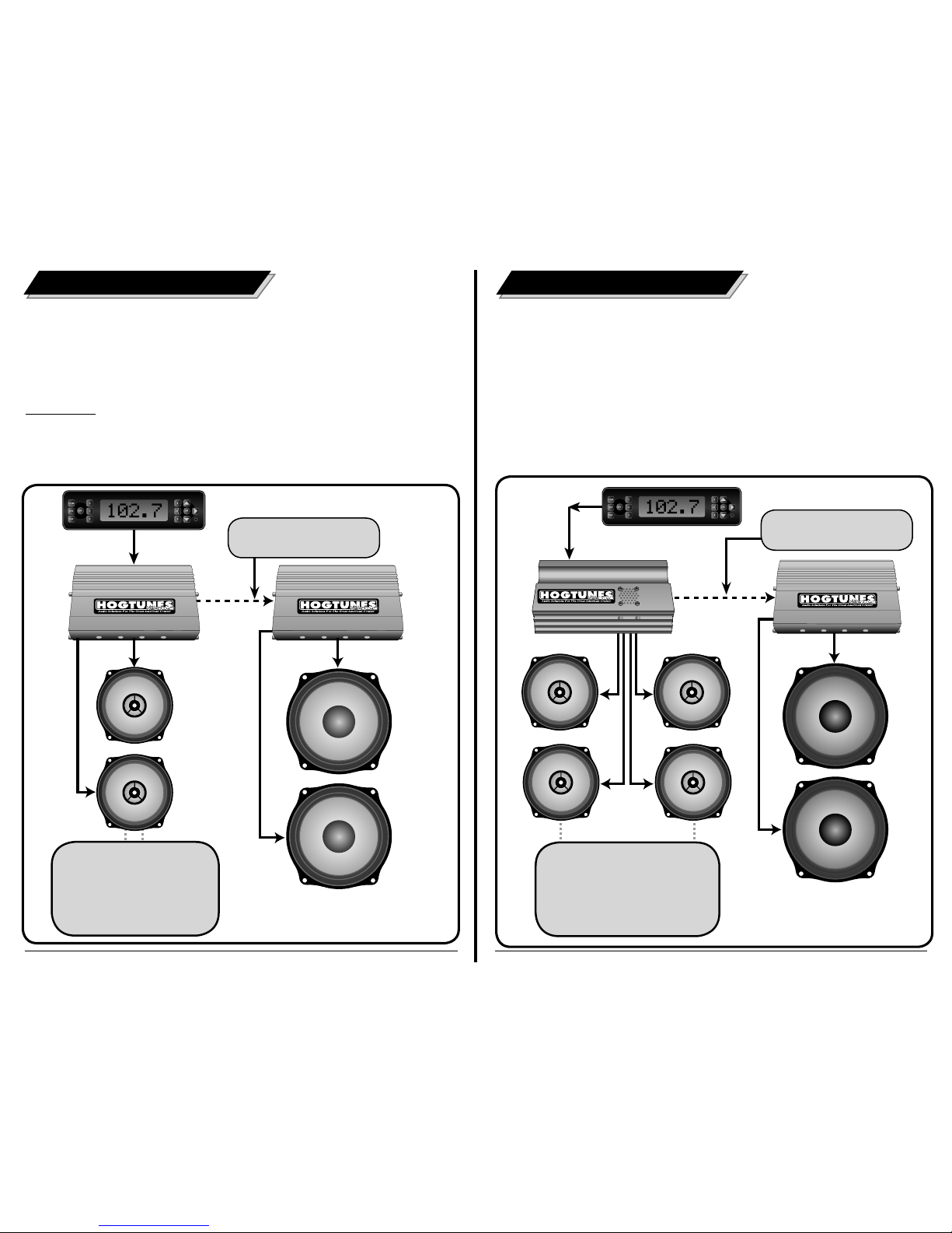
Diagram 1.3
Stock Harness and FL7 Rev Harness
Passing From Fairing To Under Tank.
Note: Harness will pass over front gas
tank mount/bolt. Opening the fuse holder
and removing the fuse will allow the wires
to pass easier. Careful!--The ring terminals
can easily scratch paint!