manuals.online logo
Brands
  1. Home
  2. •
  3. Brands
  4. •
  5. Holiday
  6. •
  7. Stove
  8. •
  9. Holiday 8425 Use and care manual

Holiday 8425 Use and care manual

OPERATING INSTRUCTIONS
AND REPAIR PARTS FOR
holiday.
CAMP STOVE
Model 8425
2BURNER CAMP STOVE
WARRANTY
We warrant all products o£ our manufacture for areasonable period of normal
operation. Such warranty covers defect in material or workmanship, but does I
not cover labor or freight charges incidental to such repair, or transportation
damage claims.
We reserve the right to repair or replace at our option such defects as may be
found, but we will not be responsible for defects caused by abuse, alteration,
misuse or accidental damages as determined by our factory Service Department,
field salesmen, or authorized Service Centers.
No other representative, dealer or distributor, or any other person is authorized
or permitted to make any other warranty or obligate the company to any liability
not strictly in accordance with this policy.
This warranty is in lieu of all other warranties expressed or implied and of all
other obligations or liabilities on our part.
PLEASE READ OPERATING INSTRUCTIONS CAREFULLY
AND FOLLOW CLOSELY
llllllllllllllllMllllllllllllllllllllllllillllllllllllllllllllllllllllllMIIIIIIIIIIIIIIIIIIIIIIIII
THERMOS^IVISION
OF KING-SEELEY /CS7"THERMOS CO.
MACOMB PLANT
MACOMB, ILLINOIS
llllllllllllllllillllllllllllllllllllllllllllllllllllllllllllllllllllltlllllllllllllllllllllllllllllllllllll
^maUea.'* OnlfiMoi <^aa«iim€Ctump^ St—>c
Continuously Manufacturad Sine* 1910
INSTRUCTIONS
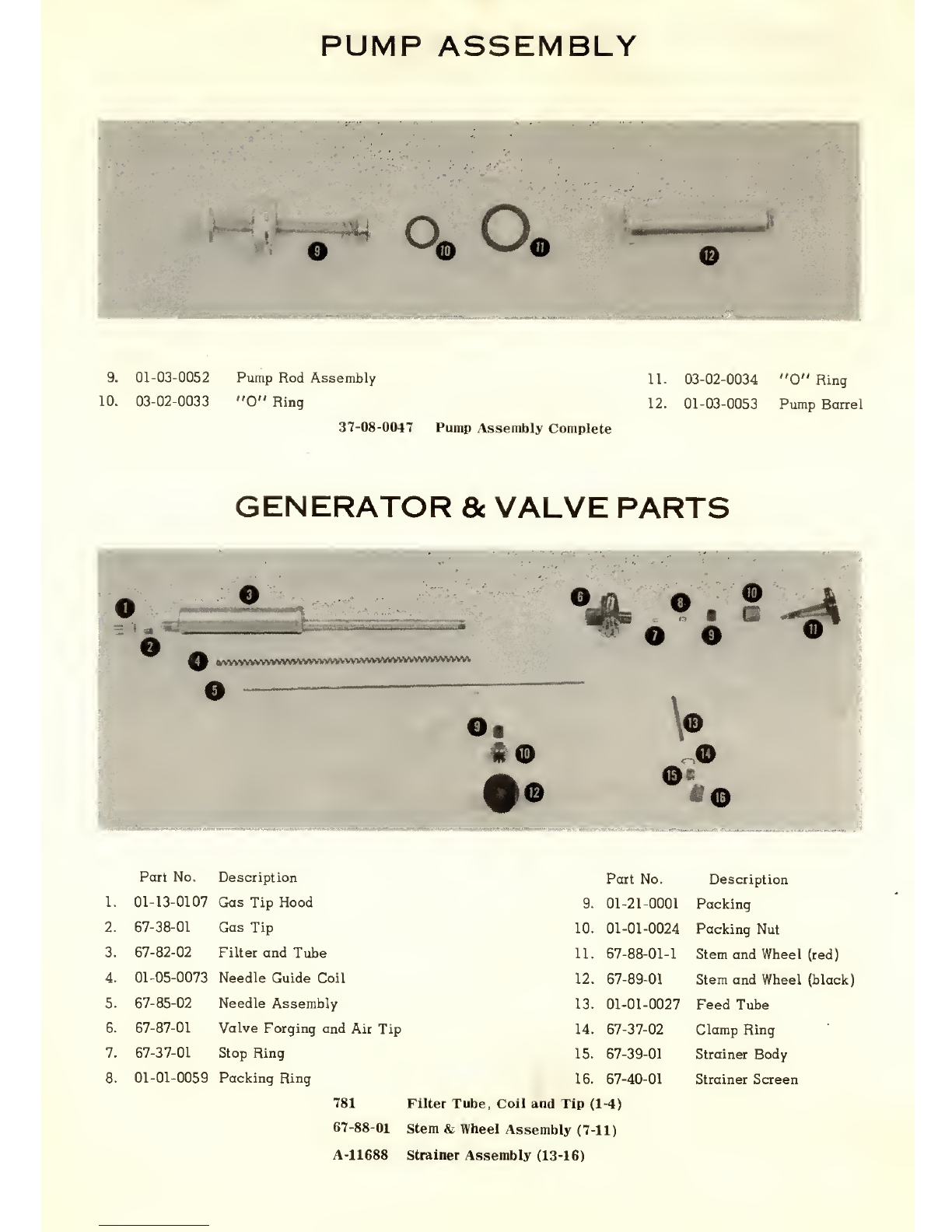
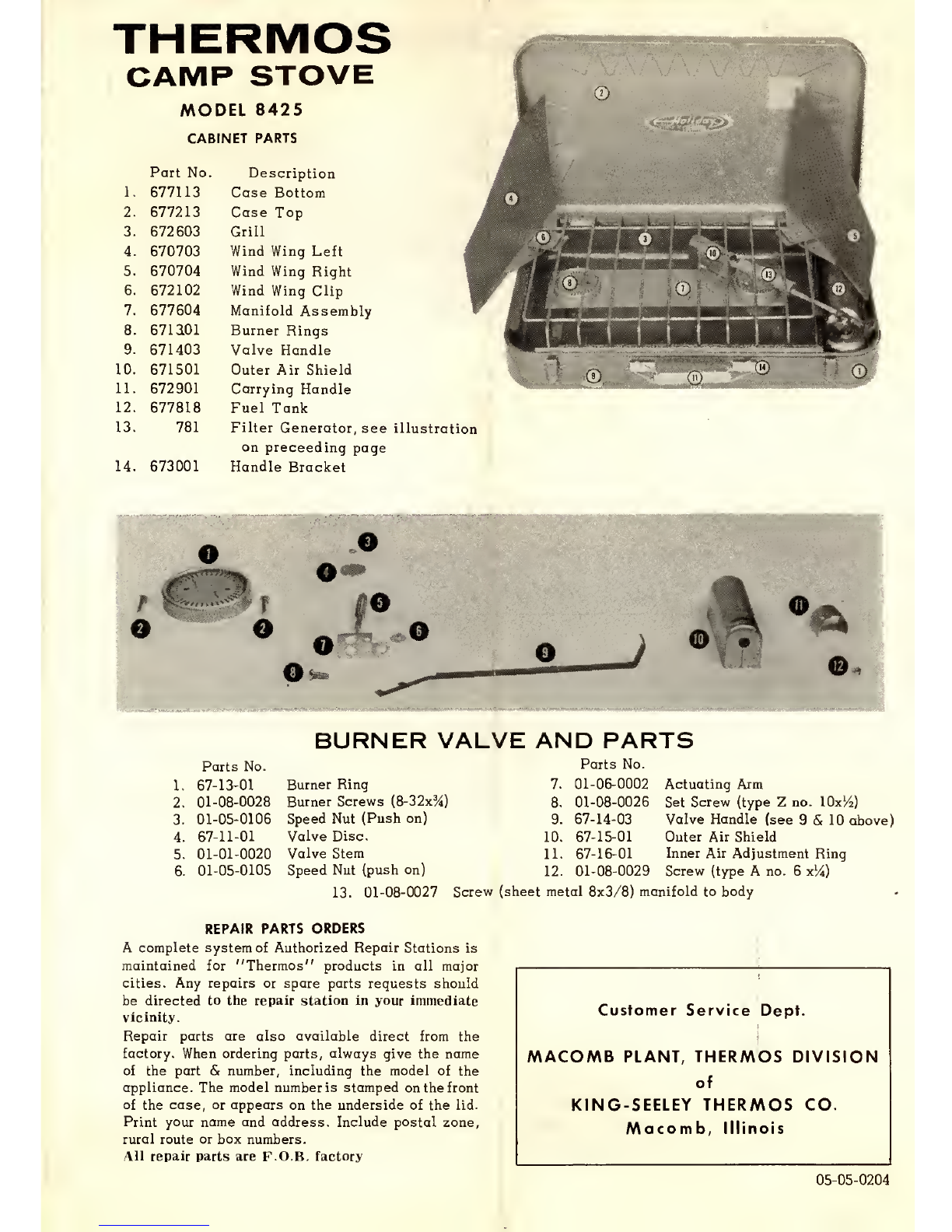
(Refer to the illustrations in the parts list to identify the various parts mentioned below.)
TO FILL
1. Remove tank from case and check both stem and
wheels on the tank valve. The black wheel or air
valve and the red valve or fuel valve must be closed
by turning to the right as far as possible.
2. Remove the pump assembly from the tank and
fill with aGOOD GRADE OF CLEAN, FRESH
FUEL.
3. Replace pump assembly by turning down snuggly
with fingers.
4. Wipe off any gasoline that has been spilled
while filling.
ATTACH TANK
1. Place tank and generator on the stove by insert-
ing the air tip hood of the generator in the hole of
the outer shield on the manifold. This is behind and
above the first or master burner.
2. Hook the tank on the case tank shield and push
down to seat firmly.
AIR PRESSURE
1. Be certain both valves are closed.
2. Pump about 35 strokes.
3. If the gas tip hood fails to seat properly within
the opening in the air shield, it may be necessary
to loosen the screws that hold the manifold in
position, and move the manifold assembly either
forward or backward.
LIGHTING
1. Valve handle for other burners must be pushed
in. Open black valve about one turn. Light match
and open red valve slowly, holding match at burner
under generator until it lights. After burning about
two minutes, slowly close black valve as this sup-
plies air only for starting. In lighting, if the flame
goes down or dies out, pump in more air. IF BLACK
VALVE IS LEFT OPEN AFTER LIGHTING OPER-
ATION, PRESSURE WILL GO DOWN.
IMPORTANT LIGHTING INSTRUCTIONS
Do not rush the lighting operation with this stove
or you will have ahigh, yellow, smoky flame.
TO LIGHT OTHER BURNER
Slide valve handle out from case and light burner.
When two burners are used it is obvious that more
gas must be supplied. The flow of gas is regulated
by opening or closing the red valve.
TO EXTINGUISH
Close red valve tight. Alittle gas will continue to
escape from the generator for amoment or two after
valve is closed. This does not indicate that the
valve leaks. Be sure the red valve is closed tight.
IMPORTANT!
After appliance has been in use, the packing In
the valve stem nuts canshrink and cause aleak.
Tighten nut with wrench to stop leak. Be sure
to empty fuel from tank when appliance is to be
out of use for some time.
GENERAL INFORMATION.
If flame has atendency to go out when closing the
black valve, open red valve wider and then close
the black valve more slowly. Best results are ob-
tained by using alow flame for about two minutes,
until the generator is thoroughly heated. If stove
burns with ayellow flame there may be liquid gas-
oline in the manifold. With instant starting gasoline
pressure stoves some liquid gasoline will pass
into the manifold. As the manifold heats, this gas-
oline will vaporize and the burners will burn with
ablue flame. If flame blows away from burner,
there is too much air pressure in the tank, or black
valve has been left open.
This stove has an air adjustment located on the
top of the outer shield above the end of the gen-
erator. For more air, loosen screw and slide to the
left in the direction of the arrow.
Extreme changes in altitude may require achange
in this shutter from the factory setting.
After the stove has operated for at least ten minutes
and the flame tends to blow away from the burner,
it is an indication that the air adjustment is too
far open. Closing it too much will give ayellow
(rather than blue) flame.
If stove will not burn, or goes out while burning,
this may be due to lack of fuel or air pressure or
the gas tip on the generator may be clogged. To
remedy, close and open red valve quickly or re-
move and clean or replace gas tip. If needle point
is bent, replace. Air or fuel orifice in the tank
valve may be clogged. To remedy, unscrew valve
from tank and clean both orifices.
If stove pops and blows out, this is probably due
to burned out rings on the burners. Replace with
new burner rings.
Should generator leak gas while stove is not burn-
ing, tighten the red valve more. If leakage still
occurs, replace the gas tip, as the orifice may have
become enlarged by the action of the needle point.
CARE OF STOVE
1. Keep cabinet and parts clean.
2. Store in adry place.
3. Clean burner periodically by removing two
screws and lifting them off manifold.
4. Empty and dry out tank before putting in storage.
5. Keep packing nuts on the two valve wheels tight
to avoid gasoline leaks.
6. Replace gas tip on generator and needle valve
occasionally.
Needle points for repair are extra long be-
cause they do not screw into the stem the same
distance. They need to be cut off and trimmed
to atapered point that extends through the tip
about one-sixteenth of an inch.
PUMP ASSEMBLY
9. 01-03-0052
10. 03-02-0033
Pump Rod Assembly
"0" Ring
37-08-0047 Pump Assembly Complete
11.
12.
03-02-0034
01-03-0053
"0" Ring
Pump Barrel
GENERATOR &VALVE PARTS
Part No. Description
1. 01-13-0107 Gas Tip Hood
2. 67-38-01 Gas Tip
3. 67-82-02 Filter and Tube
4. 01-05-0073 Needle Guide Coil
5. 67-85-02 Needle Assembly
6. 67-87-01 Valve Forging and Air Tip
7. 67-37-01 Stop Ring
8. 01-01-0059 Packing Ring
Part No. Description
9. 01-21-0001 Packing
10. 01-01-0024 Packing Nut
11. 67-88-01-1 Stem and Wheel (red)
12. 67-89-01 Stem and Wheel (black)
13. 01-01-0027 Feed Tube
14. 67-37-02 Clamp Ring
15. 67-39-01 Strainer Body
16. 67-40-01 Strainer Screen
781 Filter Tube, Coll and Tip (1-4)
67-88-01 Stem &Wheel Assembly (7-11)
A-11688 Strainer Assembly (13-16)
THERMOS
CAMP STOVE
MODEL 8425
CABINET PARTS
Part No. Description
1. 677113 Case Bottom
2. 677213 Case Top
3. 672603 Grill
4. 670703 Wind Wing Left
5. 670704 Wind Wing Right
6. 672102 Wind Wing Clip
7. 677604 Manifold Assembly
8. 671 aOl Burner Rings
9. 671403 Valve Handle
10. 671501 Outer Air Shield
11. 672901 Carrying Handle
12. 677818 Fuel Tank
13. 781 Filter Generator, see illustration
on preceeding page
14. 673001 Handle Bracket
BURNER VALVE AND PARTS

Popular Stove manuals by other brands

Horus VERTIGO 12.0 Operating, installation and maintenance manual

Horus

Horus VERTIGO 12.0 Operating, installation and maintenance manual

Hearth & Home Quadra-Fire CASTILE-MBK-C owner's manual

Hearth & Home

Hearth & Home Quadra-Fire CASTILE-MBK-C owner's manual

AMI 4E Operating and installation instruction

AMI

AMI 4E Operating and installation instruction

Quadra-Fire SAPPHIRE Sapphire Cast Iron Specifications

Quadra-Fire

Quadra-Fire SAPPHIRE Sapphire Cast Iron Specifications

Texsport 14204 operating manual

Texsport

Texsport 14204 operating manual

RIKA SOL RIKATRONIC4 operating manual

RIKA

RIKA SOL RIKATRONIC4 operating manual

Jøtul Allagash GF 300 DV Installation and operation instructions

Jøtul

Jøtul Allagash GF 300 DV Installation and operation instructions

Clarke MAJESTIC user guide

Clarke

Clarke MAJESTIC user guide

LAMINOX IDRO HYDRO Use and maintenance instructions

LAMINOX

LAMINOX IDRO HYDRO Use and maintenance instructions

Jøtul GF 305 DV IPI Installation and operation instructions

Jøtul

Jøtul GF 305 DV IPI Installation and operation instructions

Valor Inspire L Installer and owner guide

Valor

Valor Inspire L Installer and owner guide

EVA Stampaggi ISOTTA instruction manual

EVA Stampaggi

EVA Stampaggi ISOTTA instruction manual

Brixton KO-6383DU instruction manual

Brixton

Brixton KO-6383DU instruction manual

MCZ DECO' AIR 8 M1 Use and installation  manual

MCZ

MCZ DECO' AIR 8 M1 Use and installation manual

Hussong Kozy Heat CWST-ODK manual

Hussong

Hussong Kozy Heat CWST-ODK manual

TONWERK T-LINE?eco2 operating instructions

TONWERK

TONWERK T-LINE?eco2 operating instructions

Zempire 0150803 manual

Zempire

Zempire 0150803 manual

Regency FG38NG2-BRA Owners & installation manual

Regency

Regency FG38NG2-BRA Owners & installation manual

manuals.online logo
manuals.online logoBrands
  • About & Mission
  • Contact us
  • Privacy Policy
  • Terms and Conditions

Copyright 2025 Manuals.Online. All Rights Reserved.