Specifications
Description
The SAWM60 is a microprocessor controlled
rebroadcast quality, phase locked loop synthesized,
frequency fixed CATV television modulator. The single
conversion and superior SAW filtering provides
adjacent channel compatibility and spurious free
output. The SAWM60 provides 60dB output level from
50 to 860 MHz including STD and HRC offset
frequencies. The channelization configuration can be
changed by the up/down buttons located on the inside
adjustments. The modulator is shipped with all internal
adjustments preset and FCC Docket 21006 offsets are
standard. The unit conforms to FCC Docket 21006 for
frequency accuracy.
Features
•SAW filtered
•Double I.F. loop; separate audio and video.
•Composite I.F. loop (45.75 MHz)
•Automatic band splitting filters for superior carrier to
noise ratio.
•BTSC 4.5 MHz stereo capability
•Supports HRC, IRC, frequency offsets
•Front panel -30dB test point
•Five year warranty
Specifications
RF --------------------------------------------------------
Channels: 134 channels (2-135)
Frequency Range: 54 - 860 MHz
Output Level: 60 dBmV min., 62 dBmV typ. Ch.2-62
57 dBmV min., 60 dBmV typ. Ch.63-135
adjustable from front panel
Output Impedance: 75 ohm
Audio/Video Ratio: Adjustable -7 to -22 dB below video
carrier
Frequency Stability: ±5 kHz in aeronautical band
Carrier to Noise (In-band): >60 dB
Spurious Output (A/V Ratio @ -15 dB): In Band>65 dBc
Spurious Output: Outside Band (typical) >60 dBc
IF Audio/Video Frequency: Video 45.75 MHz
Audio 41.25 MHz
Video IF Output: 37 dBmV min
Audio IF Output: 15 - 30 dBmV typ. adjustment range
Composite IF : 45.75 MHz
Composite IF Output Level: 32 dBmV min
Composite IF Input Level: 35 dBmV max
Video ---------------------------------------------------------
OVER
AURAL LEVEL
MOD.
AUDIO CHANNEL
+12.5K
STD
OFFSET
HRC
+25K
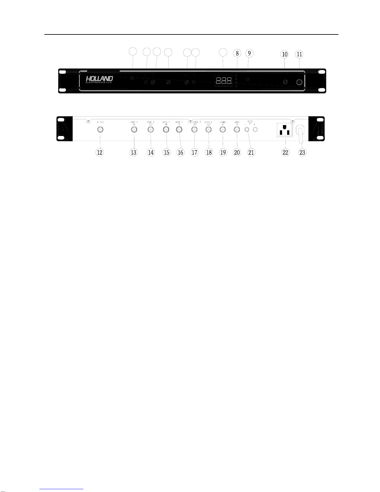
OUTPUT TEST
LEVEL POINT
30dB
CARRIER
AUDIO/VIDEO MODULATOR
MODEL SAWM60 ADJ.
POWER
LEVELOVER
MOD.
VIDEO
ADJ.
Input Level: 1 V p-p min. at 87.5% modulation
Input Level Range: 0.5 to 1.5 p-p
Input Type: Clamped video negative sync
Frequency Response: ±0.8 dB, 30 Hz to 4.2 MHz
Differential Gain: <5% (10 to 87.5% APL)
Differential Phase: <5°(10 to 87.5% APL)
Chrominance Luminance Delay: < ±50ns
Hum and Noise: -60 dB @ 87.5% modulation
Video Signal to Noise: -60 dB minimum (weighted)
Audio --------------------------------------------------------
Baseband Input Impedance: 600 ohms unbalanced
Baseband Input Level: 0.5 Vp-p for 25 kHz peak deviation
Pre-Emphasis: 75 microseconds
Flatness: -1.5dB max. 15 Hz to 15 kHz
General -----------------------------------------------------
Power Input: 100-240 VAC, 60 Hz
Operating Temperature: -10℃to +50℃
Dimensions: 19”W × 9.375”D × 1.75”H
Weight: 8 pounds
Connectors: All “F” type except RCA type for
baseband audio
NOTE: Meets FCC group delay pre-distortion correction for
color transmission.