Holley Sniper EFI HyperSpark User manual

Holley Sniper EFI HyperSpark Distributors are designed to plug and play with Sniper EFI systems. This design includes a
single Hall Effect sensor providing crankshaft speed to the ECU. The precision machined shutter wheel design ensures
accurate timing, even at very high engine speeds. They can also be used with other EFI systems that support a Hall Effect
crank signal input.
NOTE: The distributor comes with a hardened steel distributor gear that should be compatible withmost hydraulic roller
camshafts. It is recommended to consult your camshaft manufacturer prior to installation to confirm what
distributor gear material they require. When changing distributor gears, it is critical to measure the shaft diameter
OD and gear ID, before installing the new gear on the shaft.
Read this before proceeding:
Before beginning the HyperSpark Distributor installation, we recommend that you locate a CLEAN Switched 12v
Ignition source. This source needs to have 12v while cranking, and with the key in the run position. Label this
source now, as you will need to use it for Step 9 of the Distributor Installation. Do NOT connect the switched 12v
wire to a source such as the ignition coil, or starter solenoid. It may be necessary to install a 4 pole relay to
provide a clean switched 12v Ignition source, Mr. Gasket 40100G will work perfectly for this application.
DISTRIBUTOR REMOVAL:
Disconnect the battery NEGATIVE (-) cable.
1. Disconnect the power and or ground connection at the coil. Tape up any non-insulated power and ground
terminals to eliminate any chance of a shortcircuit.
2. Rotate the crankshaft in the direction of engine rotation until it reads 0 degrees on the harmonic balancer. IT IS
CRITICAL TO VERIFY THE ENGINE IS ON THE COMPRESSION STROKE AT THIS POINT!
3. Remove spark plug wires and all other wiring/vacuum hoses fromdistributor. Now is a good time to clean off any
debris that may fall into the oil pump galley.
4. Remove distributor hold-down. Lift the distributor upwards andremove.
5. As you are removing the distributor, note that the rotor rotates as you lift the distributor out of the engine. This is due
to the helical cut gear and should be taken into consideration when installing the new distributor.
Your distributor will rotate clockwise or counter-clockwise. You will need to determine the proper direction of
rotation before proceeding. See chart below.
Engine Family
Rotor Rotation
Small/Big Block Chevy
Clockwise
Chrysler Small Block
Clockwise
Ford 351W
Counter-Clockwise
Ford 302
Counter-Clockwise
BB Chrysler Wedge
Counter-Clockwise
Ford FE
Counter-Clockwise
Oldsmobile
Counter-Clockwise
Pontiac
Counter-Clockwise

2
DISTRIBUTOR INSTALL:
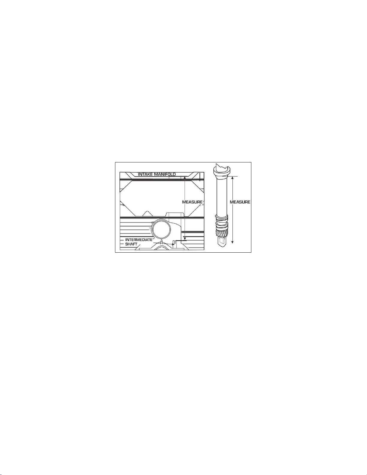
NOTE: If the engine block or heads have been milled, make sure that the distributor will fully seatand not bind or
bottom out on the oil pump drive. A quick check is to remove the distributor gasket, and make sure that the
distributor still fully seats on the mounting surface. If it does not, further investigation is needed.
1. Install the distributor gasket on the base of the distributor. If desired, apply adhesive between thegasket and
distributor to hold it in place.
2. If the engine has already been broken in/run previously and is about to be fired immediately after the distributor install,
coat the gear with motor oil. If the engine is new or will sit a while before it is fired, coat the distributor gear with a moly
paste or camshaft break-in lube. Ensure no synthetic oils are used during the installation or break-in period. We
recommend a standard 30 or 40 weight or Multi-Viscosity oil such as 10W-30 or 20W-50 to be used for the break-in
period. Engines that produce oil pressure over 70psi when COLD should utilize a racing grade mineral oil for break-in.
It is also recommended to monitor gear wear after the break-in period for several hours. Check the gear for proper
mesh, tooth alignment, andfor excessive tooth wear.
3. Position the rotor contact so it is pointing to the desired direction of the #1 spark plug wire. Insert the distributor into
the engine, ensuring that it is fully seated (see NOTE above). The rotor will rotate as you install the distributor. If it is
does not land in the location you desire, remove the distributor and back it up a tooth or two at a time until you are
satisfied with its location. You will need to make sure the oil pump drive shaft is turned in a direction that allows for the
distributor shaft to mesh with it. NOTE: An engine oil priming tool is an ideal alternative to aid in aligning the oil pump
drive shaft. Make sure that the drive shaft meshes andthe distributor fullyseats.
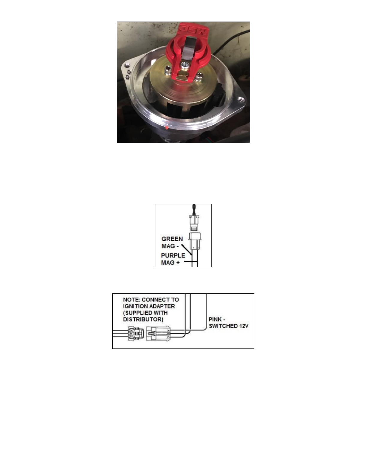
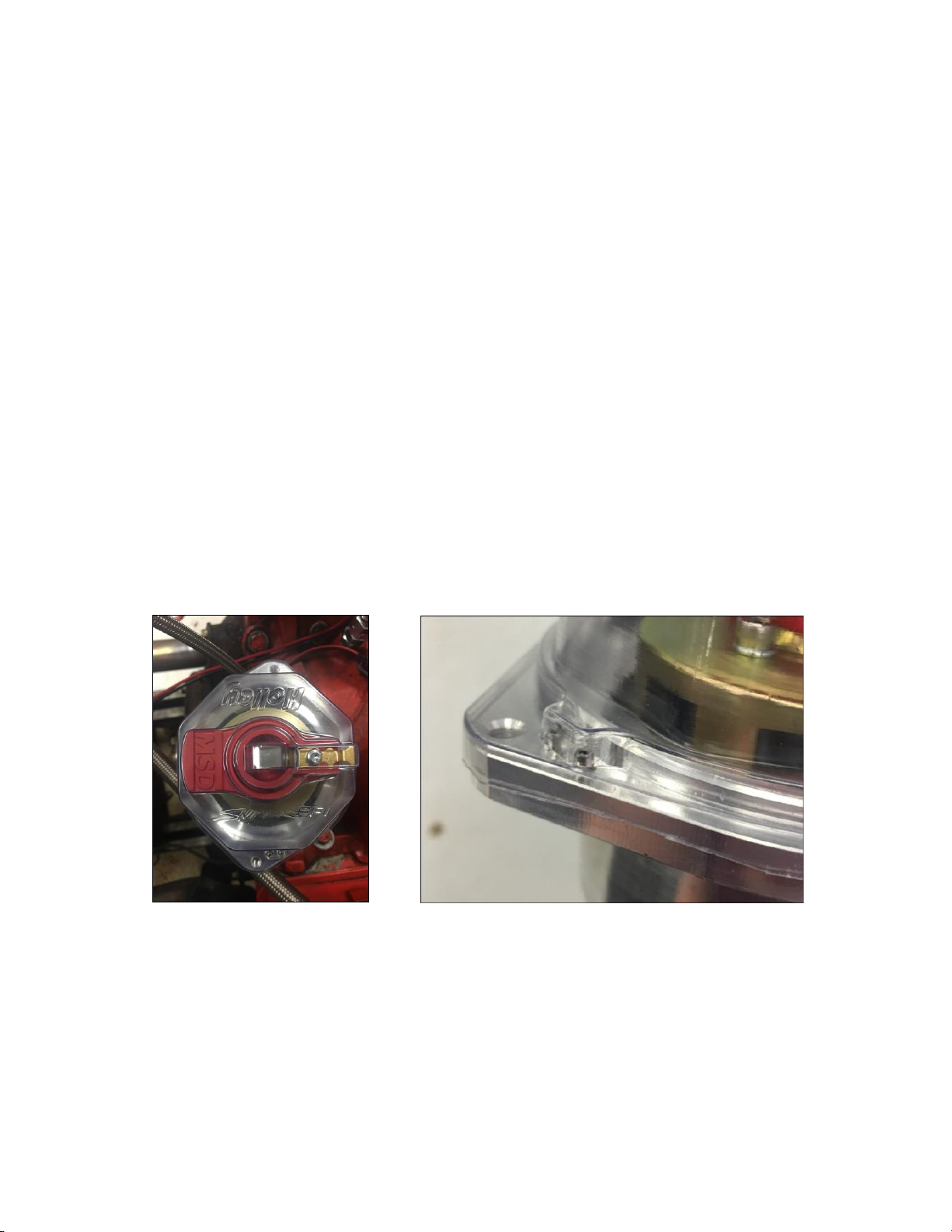
4. Next, place the provided clear distributor cap over the rotor, the cap is formed to accept the rotor, as seen below in
(Figure 1).
5. Now, rotate the distributor housing until the housing locks into the cap, this process phases the distributor housing.
The below image shows the cap and distributor housing in their “locked” position (Figure 2).
Figure 1 Figure 2
6. Tighten the distributor hold down bracket.
7. Once step 5 (Distributor Alignment) is completed, the rotor will be pointing to the cylinder #1 terminal on the
distributor cap. It can be useful to mark the distributor housing to indicate where the #1 terminal on the cap will be
(Figure 3). Note which position this is on the distributor cap. Install the cap and install the #1 plug wire. Install the rest
of the plug wires based on the engine’s firing order and rotor rotation.

3
Figure 3
NOTE: A spark plug wire retainer is supplied to secure the plug wires in place. Align the mounting bosses and use the
supplied 1.5” self-tapping Phillips screws to hold the retainer in place.
8. Next, locate the wiring harness supplied with the distributor, plug the 2 pin connector from the distributor harness into
the 2 pin connector on the Sniper EFI Main Harness (7 pin Connector). These connectors are keyed, however the
Purple and Green wires should plug into each other (Figure 4).
Figure 4
9. Now, plug the 3 pin distributor connector into the 3 pin connector on the provided wiring harness (Figure 5).
Figure 5
10. Next, terminate the Pink switched 12v wire on the 3 pin distributor wiring harness, to the clean switched 12v ignition
source that you labeled earlier.

4
UPDATE FIRMWARE:
NOTE: To use a HyperSpark Distributor with a Sniper, the system must be using these versions of firmware or later:
Handheld: 1.1.7 (tslcd35st_sniper_fw_01_01_0070.fwu)
ECU: 1.1.1 (SNIPER_01010000.eep)
Software: Version 1.1 Build 2
ECU Firmware: From Main Screen. Files>ECU HW/FW Handheld Firmware: From Main Screen. Files> Local Setup
Handheld Setup:
For New Sniper EFI Installations:
From the HOME Screen select Wizards, follow the prompts, on Step 7 you will be prompted to select your ignition type,
highlight Hyperspark Distributor (Figure 6), and press Next. Then follow the wizard prompts in the Sniper EFI handheld to
complete the setup Wizard.
Figure 6
Or:
If you already have a running engine with Sniper EFI and are upgrading the ignition system. Instead of re-running
the wizard, you can manually change your ignition type.
From the HOME Screen, select Tuning, next select System, then Ignition Setup, now press Ignition Type, and
select HyperSpark.

5
Home Screen, Select Tuning Tuning Screen, Select System System Screen, Select Ignition Setup
Figure 7 Figure 8 Figure 9
Ignition Setup, Press Ignition Type, Select HyperSpark
Figure 10
NOTE: An ignition key cycle must be completed before the change will occur in the ECU. It is also ideal after you have
cycled the ignition, to double check that the change has been saved.
Sniper EFI Software Setup:
System Parameters > Ignition > Select Ignition Type of “Sniper Distributor” from the drop-down menu.
Sniper EFI Software - System Parameters
Figure 11
Ignition Reference Angle –57.5 degrees
Inductive Delay –This parameter is used such that ignition timing does not under or over-advance as engine speed
is increased. A starting value of 100.0 usec can be used. But once the engine is running, the engine should (safely)
be run up to 3000-4000 RPM, and timing be checked such that it matches the commanded value. If it is lower than
commanded, the Inductive Delay should be increased, if higher, the delay decreased.
OUTPUT SETUP
The following should be used if triggering a MSD Capacitive Discharge type ignition box.
Dwell Time –2.0 msec

6
11. It’s time to check the timing. Remove the fuel pump relay. This will ensure that no fuel will be sprayed from the
injectors. Crank the engine over and check the timing with a timing light.
12. To make sure the ECU is getting an RPM signal, look at the “RPM” on the Initial Startup screen of the Sniper EFI
handheld. Crank the engine over and make sure it shows RPM (Figure 12). To locate this screen, from the HOME
SCREEN of the handheld, select the MONITOR icon, then select the “Monitors” screen. Here you should see an icon
named “Initial Startup”. Select this icon.
Engine RPM –This gauge should show “Stall!”, once you begin cranking the engine it will show actual engine RPM.
Figure 12
13. Next, check the timing with a timing light, it should be whatever the cranking timing is programmed to in the software
(Sniper EFI Systems use 15 degrees as the default cranking timing value). Shoot the balance with the timing light, it
should read 15 degrees on the balancer. If not, it may be necessary to loosen the distributor hold down bracket and
slightly advance or retard the ignition timing by rotating the distributor housing to make these values match. Once this
value has been met, re-tighten the distributor hold down bracket.
14. Reinstall the fuel pump relay.
15. Start the engine.
16. Once running, check the timing with a timing light and make sure it matches the commanded timing of the ECU. It is
helpful to use the “Enable Static Timing Set” feature in the handheld, this feature can lock the timing to a single value.
To find the Static Timing Menu, from the HOME SCREEN, select TUNING, then select SYSTEM. Static Timing will be
the Bottom Right icon of this screen (Figure 13). Move the sliding bar to 15 Degrees, then press the SET Icon, this
will command the engine to run at 15 Degrees of Ignition Timing.
System Menu, Select Static Timing Slide the pointer to 15, Press Set
Figure 13
17. Once synced, CAREFULLY rev the engine up to 3000-4000 RPM and make sure the timing still matches. If it is
advanced, lower the Inductive Delay value by about 20. If it is retarded, raise the Inductive Delay value about 20.
Cycle the ignition power after making this change.

7
MISCELLANEOUS COMPONENTS:
Replacement Black Cap: MSD 84313 or Holley 566-105 –Rotor MSD 8467 or Holley 566-106
P/N 8583 Bronze Gear, P/N 85832 Cast Iron Gear, P/N 85833 Replacement Steel Gear –Ford 302
P/N 8581 Bronze Gear, P/N 85812 Cast Iron Gear, P/N 85813 Replacement Steel Gear –Ford 351C-460
P/N 8585 Bronze Gear, P/N 85852 Cast Iron Gear, P/N 85834 Replacement Steel Gear –Ford 351W
P/N 8531 Replacement Cast Melonized Gear, 8472 Oversized Bronze Gear (+0.006) –Chevy
P/N 8471 Bronze Gear –(0.500”) ID Chevy
P/N 85631 Bronze Gear –Pontiac
GEAR INSTALLATION ON FORD DISTRIBUTORS:
It is recommended to send your Ford Distributor to MSD to have a new gear installed. The MSD Tech Department can
be reached at 888-258-3835. The installation process requires a press fit and the need for special tools to achieve
proper installation without damaging the shaft, gear or housing. If returning the distributor to MSD is not an option, a
quality machine shop may also be able to install your new gear.
1. With the endplay of the distributor shaft removed, measure the distance from the bottom of the gear to the bottom of
the mounting flange (Figure 14). It should be within the specificationsshown.
2. Scribe a mark on the shaft at the bottom of the gear. This will aid in the installation position of the newgear.
3. Remove the original roll pin and remove the press fit gear. Use extreme care not to damage the end ofthe shaft where
it meshes with the oil pump.
4. Position the gear so the new roll pin will enter the shaft 90° from the original hole. (Lining up the original hole is
possible, but a new hole will likely be machined.)
5. Press the new gear into position on the shaft. Measure the distance as shown in (Figure 14) before drilling the new
roll pin hole.
6. Carefully drill a 0.125” hole through the shaft using the gear as a guide.
7. Install the new 1/8” spiral roll pin.
Figure 14 Gear Installation Specifications
CAUTION: If the gear is installed improperly, severe damage to the
distributor and/or engine block will occur!

8
CHECKING GEAR MESH:
It is recommended to check for proper gear mesh between the cam gear and distributor gear. To do this, coat
the distributor gear with moly grease and install the distributor. Next, crank the engine over several times.
Before pulling the distributor out, make sure the rotor is in the position that lines up with the original removal
mark. Then pull the distributor out and inspect the gear pattern shown on the grease. The proper mesh will
leave an even pattern in the middle of the gear. Adjust the slip collar to obtain the correct mesh.
Checking the Oil Pump to Distributor Shaft Overlap:
The proper overlap between the distributor shaft and the oil pump shaft is very important. The tongue of the
distributor shaft should fit into the groove of the oil pump shaft by at least 1/4". Tocheck this:
Measure the distance between the base of the slip collar to the tip of the distributor shaft (
Figure 15
).
Using a straight edge, measure the distance from the intake manifold distributor flange to the top of the oil
pump intermediate shaft (
Figure 15
).
Takethetwomeasurementsandsubtractthem.Thedifferenceistheoverlap. Ifthereisnotenough clearance
or too much clearance, a different oil pump intermediate shaft is required.
Figure 15 –Measuring Oil Pump Shaft Overlap
© 2018 Holley Performance Products. All Rights Reserved. Tous Droits Réservés.
199R11525
Revision Date: 5-14-18
FRM 34827
Table of contents