Holley 12-700 User manual

HP FUEL PUMPS
P/N 12-700 & 12-890
Installation Instructions 199R10569
WARNING! THESE INSTRUCTIONS MUST BE READ AND FULLY UNDERSTOOD BEFORE BEGINNING INSTALLATION. FAILURE TO
FOLLOW THESE INSTRUCTIONS MAY RESULT IN POOR PERFORMANCE, VEHICLE DAMAGE, PERSONAL INJURY, OR DEATH.
IF THESE INSTRUCTIONS ARE NOT FULLY UNDERSTOOD, INSTALLATION SHOULD NOT BE ATTEMPTED. PLEASE CONSULT
HOLLEY TECH SERVICE OR A QUALIFIED MECHANIC.
NOTE: NOT FOR USE WITH METHANOL! Will work with E-85!
APPLICATIONS:
Naturally
Aspirated
Forced
Induction
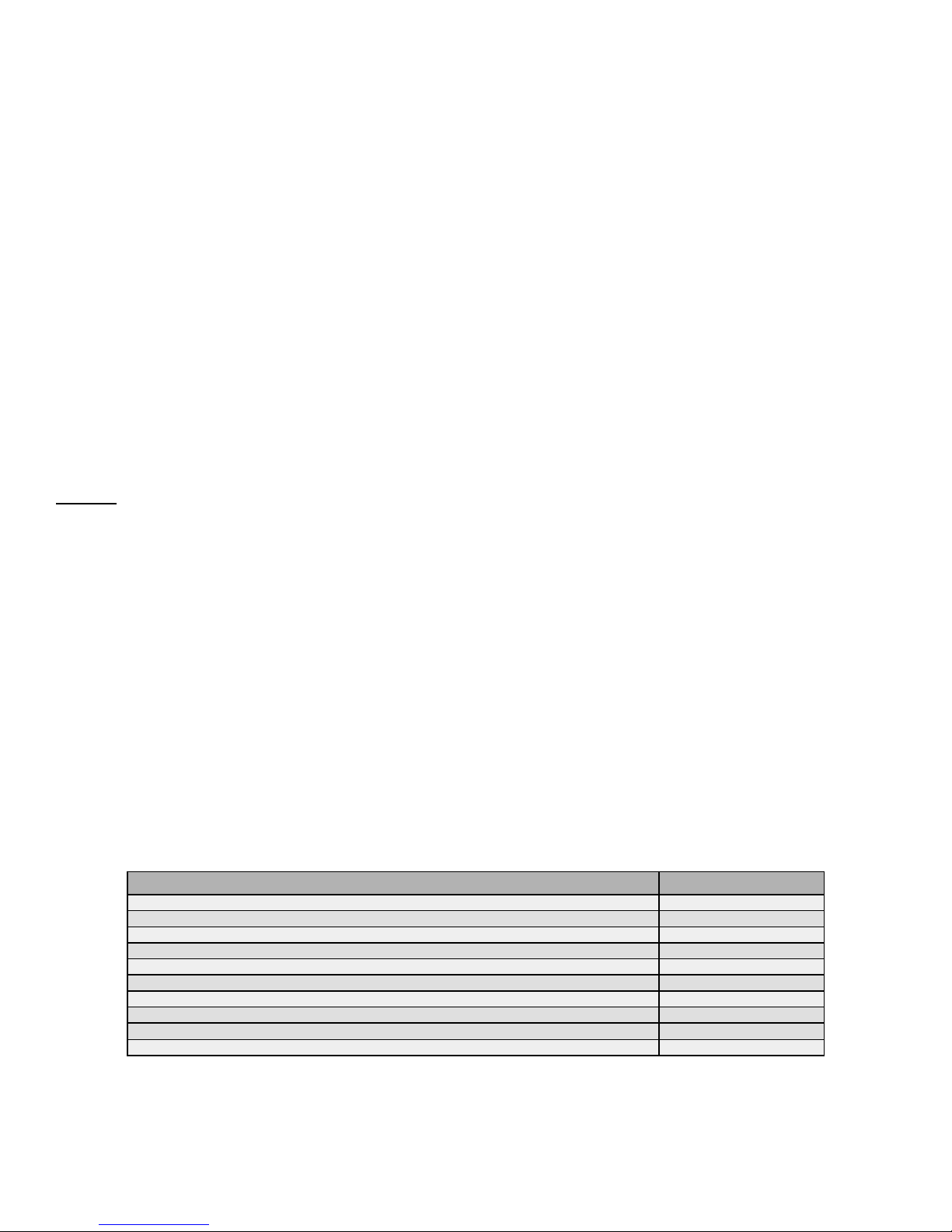
Inlet Outlet Inlet Outlet Return Pre Post Pre Post Carb EFI
12-700
75 @ 8PSI
57 @ 43PSI
47 @ 60 PSI
Street/Strip Gasoline / Diesel Yes
900
700
550
690
530
430
-8AN -8AN -6 AN -6AN -6AN 162-564 162-555 162-564 162-554 12-845 12-846 13 Amps
12-890
96 @ 8PSI
76 @ 43PSI
70 @ 60 PSI
Street/Race Gasoline / Diesel Yes
1050
900
800
800
700
600
-8AN -8AN -8AN -6AN -6AN 162-564 162-555 162-564 162-554 12-845 12-846 18 Amps
The pumps below do not have an internal bypass. A bypass style regulator and return line are required.
Max Amp
Draw
Part
Number
Holley Recommendations for Peak Performance
Pump Fitting
Size
Recommended
Regulator
Fuel Filter
(Carbureted)
Fuel Filter
(Fuel injected)
Max HP*
GPH Flow at Rated
PSI and 13.5V
Application
Fuel Compatibility
Minimum
Recommended Line
Compatible up
to 18.5V
PARTS REQUIRED FOR INSTALLATION:
Pre-Filter
Post-Filter
Relay Kit (30amp minimum) – Holley P/N 12-753 or equivalent
Safety Shutoff Switch (Holley P/N 12-810 or equivalent)
Fuel hose & fittings
Wire & connectors
Mounting hardware
NOTE: These pumps are not serviceable in the field. Contact Holley tech service for fuel pump service.
INTRODUCTION:
Congratulations on your purchase of the Holley HP Fuel Pump. This instruction sheet contains all the information needed to install this fuel pump.
Please read all the WARNINGS and NOTES. They contain valuable information that can save you time and money. Holley Performance Products
cannot and will not be responsible for any alleged or actual engine or other damage, or other conditions resulting from misapplication of the fuel pumps
and fuel pressure regulators described herein. However, it is our intent to provide the best possible products for our customer; products that perform
properly and satisfy your expectations. Should you need information or parts assistance, please contact Technical Service at 1-270-781-9741, M-F, 8
a.m. to 6 p.m. & Sat. 9 a.m. to 3 p.m. CST. Please have the P/N ready when calling.
NOTE: A screen type pre-filter (100 micron), a top quality post fuel filter, fuel hose and clamps, 12 gauge wire, fuel fittings, assorted terminals, a relay
kit (12-753), and an optional safety shut-off switch (12-810) is required to complete the installation of the Holley HP fuel pump. These parts
are not included with the fuel pump.
NOTE: These Holley HP fuel pumps require the use of a bypass style fuel pressure regulator (Part number 12-845 for carbureted applications and 12-
846 for EFI applications).
NOTE: The Holley HP fuel pump utilizes o-ring sealed inlet/outlet ports. The ports utilize ¾-16 O-ring (-8AN) threads. These ports are not pipe
thread, therefore Do not use thread sealant.
NOTE: Holley ALWAYS RECOMMENDS using our oil pressure safety shut-off switch, part number 12-810.
PUMP MOUNTING AND INSTALLATION:
The best location for mounting any electric fuel pump is the rear of the vehicle, near the fuel tank and in a position even with or below the bottom of the
tank, allowing the fuel to be gravity fed to the pump. The pump should be mounted on a solid member, such as the chassis, with the pump
outlet pointing forward or upward. Avoid exposure of the pump and fuel lines to moving parts and to any hot areas, such as the exhaust manifold.
The pump should not be mounted in an enclosed area, such as the vehicle’s trunk. Follow the steps below for mounting the pump.

2
WARNING! THE PUMP MUST BE PLACED WHERE INTERFERENCE BETWEEN THE VEHICLE’S BODY AND ITS CHASSIS MOVEMENT IS
AVOIDED. THE PUMP AND ITS CONNECTING HOSES MUST NOT BE SUBJECTED TO LOW GROUND CLEARANCE, WHERE ANY
FLYING ROCKS OR ROAD DEBRIS CAN CAUSE DAMAGE. FAILURE TO AVOID THESE HAZARDS WILL LEAD TO PUMP DAMAGE,
WHICH COULD RESULT IN FIRE AND/OR PROPERTY DAMAGE, SERIOUS INJURY, AND/OR DEATH.
1. Select a mounting site as close as possible to the fuel tank and away from possible sources of heat as detailed previously.
2. A template of the pump mounting holes is included on the last page. Use the included paper template and drill (4) ¼ holes.
3. Mount the pump (outlet pointing forward) using (4) ¼ bolts (bolts not included).
NOTE: To ensure pump life and flow efficiency, a 100 micron pre-filter must be installed between the tank and the pump inlet. The filter should be
supported in such a manner that it does not hang from the fuel lines. Pre and Post filters can be mounted directly to the pump if space
allows.
4. Install the recommended AN fuel fittings. (Refer to the chart on page 1 for minimum recommended fuel fitting and hose size)
5. Connect the fuel supply line from the tank to the pre-filter and then to the inlet port of the pump. Connect the main fuel feed line to the outlet
port of the pump, then to the post filter. See Figures 1a and 1b.
NOTE: Avoid unnecessary restrictions, such as sharp bends and undersized fuel fittings and hoses. Avoid routing fuel lines in areas that would cause
chafing. All fuel line connections must be leak proof.
WARNING! IF SPLICING INTO EXISTING FUEL LINES, USE EXTREME CARE TO AVOID CONTAMINATING THE LINE WITH RUBBER OR
METAL SHAVINGS, AS THIS WILL DAMAGE THE PUMP. IF THE FUEL LINE HAS BEEN CUT, IT IS ESSENTIAL THAT IT BE
CLEANED TO ENSURE THAT NO METAL OR RUBBER PARTICLES ENTER THE FUEL SYSTEM. THIS IS PERFORMED BY
BLOWING THE LINE CLEAN WITH COMPRESSED AIR. HOLLEY DOES NOT RECOMMEND THE PROCEDURE WHERE THE COIL
WIRE IS DISCONNECTED, THE ENGINE IS CRANKED, AND THE FUEL IS COLLECTED IN A CONTAINER. SPARKING CAN OCCUR
DURING THIS PROCEDURE, WHICH MAY RESULT IN A FIRE AND/OR EXPLOSION.
WARNING! DO NOT OVER TIGHTEN THE FITTINGS ON THE FUEL PUMP. TORQUE the fittings in the pump as follows. (-8AN to 270-300
in./lbs. and -6AN to 150-170 in./lbs.)
USING A FUEL PRESSURE REGULATOR WITH A FUEL PUMP:
NOTE: A return style fuel pressure regulator is required for use with the Holley HP fuel pumps. Please refer to the chart on page one for
recommended fuel pressure regulators. Refer to figures 1a,and 1b,for recommended plumbing scenarios. .
NOTE: Refer to the installation instruction included with the fuel pressure regulator for steps on mounting and adjustments
NOTE: Depending on your application, choose one of the following examples:
Figure 1a (Carb applications only)

3
Figure 1b (Both carb & fuel injection applications)
WIRING:
WARNING! USE A MINIMUM OF 12 GAUGE WIRE. BE SURE TO CRIMP OR SOLDER ALL CONNECTORS SECURELY AND CLEAN ANY AREA
WHERE GROUND LEADS WILL BE FASTENED. FAILURE TO USE THE MINIMUM WIRE GAUGE COULD RESULT IN A PUMP
MALFUNCTION AND/OR ELECTRICAL FIRE, RESULTING IN PROPERTY DAMAGE, SERIOUS INJURY, AND/OR DEATH.
There are 2 methods to wire the pump: (1) To wire the fuel pump with a relay. (2) To wire the fuel pump with an oil pressure safety switch and relay.
(1) WIRING THE FUEL PUMP WITH A RELAY:
NOTE: You will need Holley Fuel pump relay kit P/N 12-753 or equivalent 4-wire relay.
1. Disconnect the cables from the battery.
2. Mount relay on firewall of engine compartment or other suitable location using a sheet metal screw.
WARNING! Before punching or drilling a hole in the firewall, make sure you know what is on the other side to avoid puncturing equipment
such as heater cores, air-conditioning system equipment, hoses, or wiring.
3. Plug the fuel pump relay harness into the relay, until it locks into place.
4. If using a Holley relay, connect the black wire of the relay harness to a good clean ground using 12 gauge wire.

4
5. Connect the Green/Black wire of the relay harness to a switched 12V source.
6. Connect one of the red wires of the relay harness to the positive wire (red wire) of the fuel pump.
7. Connect the black wire of the fuel pump to a good clean chassis ground using a ring terminal.
8. Attach the in-line fuse holder to the remaining red wire. After attaching the fuse holder, insert a 25A fuse and connect to the positive side of the
battery using 12 gauge wire.
9. Reconnect the battery cables.
Figure 2
(2) WIRING THE FUEL PUMP WITH AN OIL PRESSURE SAFETY SWITCH AND RELAY:
One method is to wire the pump to a switched 12-volt source (providing power only when the engine is running) located at the vehicle’s electric panel.
To ensure this condition, the installation of a Holley 12-810 oil pressure safety switch is recommended for installation into the wiring circuit. This will
ensure that the pump will not continue to operate after the engine is shut off and/or when the key is left in the “ON” position. If the pressure switch is to
be used, follow the installation instructions as outlined below (refer to Figure 3). Use 12 gauge wire for power (BAT+) and ground wires.
1. Disconnect the cables from the battery.
2. Remove the original equipment oil pressure switch and retain.
3. Screw a 1/8” pipe nipple into the hole from which the original pressure switch was removed. Use any suitable thread sealant on all fittings, taking
care to avoid any excess that might contaminate the engine.
4. Screw a 1/8” pipe tee onto the nipple and position it in a manner to facilitate the installation of the original oil pressure switch and the new oil
pressure safety switch in the remaining two holes.
5. Screw in the two switches and reconnect the lead to the original equipment oil pressure switch.
NOTE: The pump oil pressure switch will normally have three terminals marked: C (common), NC (normally closed), and NO (normally open).

5
+
Figure 3
6. Mount relay on firewall of engine compartment using a sheet metal screw.
WARNING! Before punching or drilling a hole in the firewall, make sure you know what is on the other side to avoid puncturing equipment
such as heater cores, air-conditioning system equipment, hoses, or wiring.
7. Plug the fuel pump relay harness into the relay, until it locks into place.
8. Connect the black wire of the relay harness to a good clean ground using 12 gauge wire.
9. Connect the Green/Black wire of the relay harness to the terminal marked “C” on the oil pressure safety switch.
10. Connect one of the red wires of the relay harness to the positive wire (red wire) of the fuel pump.
11. Connect the black wire of the fuel pump to a good clean chassis ground using a ring terminal
12. Attach the in-line fuse holder to the remaining red wire of the relay harness. After attaching the fuse holder, insert a 25A fuse and connect to the
positive side of the battery using 12 gauge wire.
13. Connect the terminal marked “NO” of the safety switch to a switched 12V source.
14. Connect the terminal marked “NC” of the safety switch to the starter terminal that’s hot (12V) during cranking only.
15. Reconnect the battery cables.
SERVICE PARTS AND ACCESSORIES:
ITEM
PART NUMBER
Chevy Small Block Mechanical Pump Block-Off Plate
12-814
Chevy Big Block Mechanical Pump Block-Off Plate
12-813
0-15 PSI Fuel Pressure Gauge (non-liquid filled) 1-1/2” Dia. 1/8” NPT
26-500
0-30 PSI Fuel Pressure Gauge (non-liquid filled) 1-1/2” Dia. 1/8” NPT
26-502
0-15 PSI Electric Fuel Pressure Gauge (dash mount)
26-503
0-15 PSI Fuel Pressure Gauge (liquid filled) 1-1/2” Dia. 1/8” NPT
26-504
0-30 PSI Fuel Pressure Gauge (liquid filled) 1-1/2” Dia. 1/8” NPT
26-505
30AMP Fuel Pump Relay Kit
12-753
90 Elbow for Attachment to Holley Fuel Line
26-69
Safety Shut Off Switch
12-810

6
Holley Technical Support
Phone: 1-270-781-9741 Fax: 1-270-781-9772
For online help, please refer to the Tech Service section of our website: www.holley.com
199R10569
Revision Date: 6-12-12
This manual suits for next models
1
Table of contents
Other Holley Water Pump manuals