Holley VR2 User manual

HOLLEY VR2 FUEL PUMPS
P/N 12-3000 & 12-3000-2
Installation Instructions 199R10975
WARNING! THESE INSTRUCTIONS MUST BE READ AND FULLY UNDERSTOOD BEFORE BEGINNING INSTALLATION.
FAILURE TO FOLLOW THESE INSTRUCTIONS MAY RESULT IN POOR PERFORMANCE, VEHICLE DAMAGE,
PERSONAL INJURY, OR DEATH. IF THESE INSTRUCTIONS ARE NOT FULLY UNDERSTOOD, INSTALLATION
SHOULD NOT BE ATTEMPTED. PLEASE CONSULT HOLLEY TECH SERVICE OR A QUALIFIED MECHANIC.
NOTE: DESIGNED FOR GASOLINE AND INTERMITTENT NON-HIGHWAY USE WITH METHANOL & E85.
APPLICATIONS:
Naturally
Aspirated
Forced
Induction
Inlet Outlet Inlet Outlet Return Pre Post Pre Post Carb EFI
12-3000 Yes
Street/Strip
Race
Pump Gas,
Race Gas,
Methanol*,
E-85*
323@ 8 PSI
276@ 43 PSI
254@ 60 PSI
169 @ 130 PSI
4800
4400
4000
3000
3600
3350
3200
2300
-16AN -10AN -16AN -10AN -8AN 162-577 162-576 162-577 162-575
12-852
12-865
12-851
12-864
38 Amps
12-3000-2 Yes
Street/Strip
Race
Pump Gas,
Race Gas,
Methanol*,
E-85*
323@ 8 PSI
276@ 43 PSI
254@ 60 PSI
169 @ 130 PSI
4800
4400
4000
3000
3600
3350
3200
2300
-10AN
(qty 2)
-10AN
-10AN
(qty 2)
-10AN -8AN 162-577 162-576 162-577 162-575
12-852
12-865
12-851
12-864
38 Amps
Minimum Recommended
Line Size
Fuel Filter
(Carbureted)
Fuel Filter
(Fuel injected)
Recommended
Regulator
*Compatible for methanol and E85 for competitive drag race use only- when draining and flushing after each race event
** HP estimates are based on gasoline. Estimates calculated at 18.5V and at .5 BSFC NA and .65 BSFC FI. Individual systems will vary based on fuel system design, regulator type, fuel cell location, launch G’s, etc.
Max Amp
Draw
The pumps below do not have an internal bypass. A bypass style regulator and return line are required.
Part
Number
Compatible
up to 18.5V
Application
Fuel
Compatibility
GPH Flow at
Rated PSI
and 13.8V
Holley Recommendations for Peak Performance
Max HP**
Pump Fitting Size
PARTS REQUIRED FOR INSTALLATION:
One Pre-Filter for the 12-3000 & two Pre-Filters for the 12-3000-2.
Post-Filter
Relay Kit (30amp minimum) –Holley P/N 12-753 or equivalent
Fuel hose and fittings (12-3000 has a single -16AN O-ring Inlet and a single -10AN O-ring Outlet)
(12-3000-2 has dual -10AN O-ring Inlets and a single -10AN O-ring Outlet)
Wire & connectors
Mounting hardware
NOTE: These pumps are not serviceable in the field. Contact Holley tech service for fuel pump service.
INTRODUCTION:
Congratulations on your purchase of the Holley VR2 Fuel Pump. This instruction sheet contains all the information needed to install
this fuel pump. Please read all the WARNINGS and NOTES. They contain valuable information that can save you time and money.
Holley Performance Products cannot and will not be responsible for any alleged or actual engine or other damage, or other conditions
resulting from misapplication of the fuel pumps and fuel pressure regulators described herein. However, it is our intent to provide the
best possible products for our customer; products that perform properly and satisfy your expectations. Should you need information or
parts assistance, please contact Technical Service at 1-270-781-9741, M-F, 8 a.m. to 6 p.m. & Sat. 9 a.m. to 3 p.m. CST. Please have
the P/N ready when calling.
NOTE: A screen type pre-filter (100 micron), a top quality post fuel filter, fuel hose and clamps, 12 gauge wire, fuel fittings, assorted
terminals and a relay kit (P/N 12-753) is required to complete the installation of the Holley VR2 fuel pump. These parts are not
included with the fuel pump.
NOTE: These Holley VR2 fuel pumps require the use of a bypass style fuel pressure regulator (P/N 12-852 for the 2-port & 12-865 for
the 4-port) for carbureted applications and (P/N 12-851 for the 2-port & 12-864 for the 4-port) for EFI applications.
NOTE: The Holley VR2 fuel pump utilizes o-ring sealed inlet/outlet ports. These ports are not pipe thread, therefore DO not use
thread sealant.
PUMP MOUNTING AND INSTALLATION:
The best location for mounting any electric fuel pump is the rear of the vehicle, near the fuel tank and in a position even with or below
the bottom of the tank, allowing the fuel to be gravity fed to the pump. The pump should be mounted on a solid member, such as
the chassis, with the pump outlet pointing forward. Avoid exposure of the pump and fuel lines to moving parts and to any hot
areas, such as the exhaust manifold. The pump should not be mounted in an enclosed area, such as the vehicle’s trunk. Follow the
steps below for mounting the pump.

2
WARNING! THE PUMP MUST BE PLACED WHERE INTERFERENCE BETWEEN THE VEHICLE’S BODY AND ITS CHASSIS
MOVEMENT IS AVOIDED. THE PUMP AND ITS CONNECTING HOSES MUST NOT BE SUBJECTED TO LOW
GROUND CLEARANCE, WHERE ANY FLYING ROCKS OR ROAD DEBRIS CAN CAUSE DAMAGE. FAILURE TO
AVOID THESE HAZARDS WILL LEAD TO PUMP DAMAGE, WHICH COULD RESULT IN FIRE AND/OR PROPERTY
DAMAGE, SERIOUS INJURY, AND/OR DEATH.
1. Select a mounting site as close as possible to the fuel tank and away from possible sources of heat as detailed previously. Mount
the controller close to the pump taking the harness length into consideration while choosing a mounting location.
2. Templates of the pump and controller mounting holes are included at the end of this manual. Use the included paper template and
drill (4) 1/4 holes for the pump and #8-32 for the controller.
3. Mount the pump (outlet pointing forward) using (4) 1/4 bolts (not included). Mount the controller using #8-32 bolts (not included).
NOTE: To ensure pump life and flow efficiency, a 100 micron pre-filter must be installed between the tank and the pump inlet. The
filter should be supported in such a manner that it does not hang from the fuel lines. Pre and Post filters can be mounted
directly to the pump if space allows.
4. Install the recommended AN fuel fittings. (Refer to the chart on page 1 for minimum recommended fuel fitting and hose size)
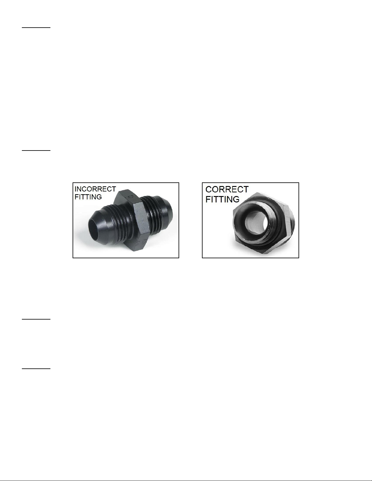
WARNING! This pump is not designed to use a standard conical seat style union in the inlet or outlet of the pump. Example:
Part # AT981510ERL (Figure 1). Use of this style fitting will restrict flow and WILL lead to poor performance and
potential pump failure. The ONLY correct fitting to use for the 12-3000-2 is TWO of the contoured port fitting with
an O-ring seal such as Part # AT985010ERL (Figure 2). The ONLY correct fitting to use for the 12-3000 is a
contoured port fitting with an O-ring seal such as Part # AT985016ERL (Figure 2).
Figure 1 Figure 2
5. Connect the fuel supply line from the tank to the pre-filter and then to the inlet port of the pump. Connect the main fuel feed line
to the outlet port of the pump, then to the post filter. See Figures 4a and 4b. If using a pump with dual inlets, both inlets MUST be
plumbed or pump failure will occur! See Figure 4c.
NOTE: Avoid unnecessary restrictions, such as sharp bends and undersized fuel fittings and hoses. Avoid routing fuel lines in areas
that would cause chafing. All fuel line connections must be leak proof.
WARNING! IF SPLICING INTO EXISTING FUEL LINES, USE EXTREME CARE TO AVOID CONTAMINATING THE LINE WITH
RUBBER OR METAL SHAVINGS, AS THIS WILL DAMAGE THE PUMP. IF THE FUEL LINE HAS BEEN CUT, IT IS
ESSENTIAL THAT IT BE CLEANED TO ENSURE THAT NO METAL OR RUBBER PARTICLES ENTER THE FUEL
SYSTEM. THIS IS PERFORMED BY BLOWING THE LINE CLEAN WITH COMPRESSED AIR. HOLLEY DOES NOT
RECOMMEND THE PROCEDURE WHERE THE COIL WIRE IS DISCONNECTED, THE ENGINE IS CRANKED, AND
THE FUEL IS COLLECTED IN A CONTAINER. SPARKING CAN OCCUR DURING THIS PROCEDURE, WHICH MAY
RESULT IN A FIRE AND/OR EXPLOSION.
WARNING! DO NOT OVER TIGHTEN THE FITTINGS ON THE FUEL PUMP. TORQUE the fittings in the pump as follows.
(-16AN to 700-840 in. /lbs., -10AN to 360-430 in. /lbs., -8AN to 270-300 in. /lbs. and -6AN to 150-170 in. /lbs.)
USING A FUEL PRESSURE REGULATOR WITH THE VR2 FUEL PUMP:
NOTE: A return style fuel pressure regulator is required for use with the Holley VR2 fuel pumps. Please refer to the chart on page one
for recommended fuel pressure regulators. Refer to figures 1a and 1b for recommended plumbing scenarios.
NOTE: Refer to the installation instruction included with the fuel pressure regulator for steps on mounting and adjustments.
NOTE: Depending on your application, choose one of the following examples:

3
Figure 4a (Carb applications only)
Figure 4b (Both carb & fuel injection applications)
Figure 4c
(If using a pump with dual inlets, connect the fuel lines as shown and plumb the rest according to Figures 4a, 4b, or 4c.)

4
INTRODUCTION:
The Holley BLDC (Brushless DC Controller) is primarily designed to be used in conjunction with the Holley VR2 fuel pump. The
controller is designed to operate stand-alone or to be used as a slave device via a ground input.
OPERATION:
The BLDC has three (3) inputs: (Red) power, (Black) ground, and (Yellow) signal. The signal wire controls how the BLDC controls the
fuel pump.
100% Duty Cycle Setup:
The first configuration, which is the simplest mode, is the controller operates the fuel pump at 100% duty cycle based on a single binary
input. (The yellow signal wire is not used). The schematics in Figure #5 and #6 show this installation. These schematics will guide you
for the controller installation with relays.
50% Duty Cycle Setup:
In a typical usage the controller would be in the 50% duty cycle mode (Yellow input signal wire to ground). This configuration would
allow the user to control the fuel pump duty cycle from 50% to 100% via a grounding input. Any switch or triggering device can be
installed in line between the yellow wire and ground. As long as it can provide a ground at low demand and remove that ground at high
demand, it can operate the controller. This could be done by a toggle switch, TPS switch, any aftermarket EFI system, a nitrous
controller, etc…
An example would be once the (TPS) throttle is depressed to a user set position the switch would disengage (“open”) the ground signal
and command the controller into a 100% duty cycle mode.
**Since there are many signal methods that can be used, please refer to the schematics of the particular switch or triggering
system that you are using to verify the (yellow) signal wire connections.
We will cover using this controller in conjunction with the Holley EFI system in the setup section on page 7.
LED OPERATION:
LED [GREEN] –Fuel pump running, no faults.
LED [YELLOW] –Attempting to start fuel pump.
LED [RED] –Low battery voltage (< 8Vdc)
LED [RED] - flash –Unable to start fuel pump.
LED Firmware Rev Indication
1. Disconnect fuel pump connector.
2. Apply nominal power to BLDC controller.
3. LED will be LED [YELLOW] for approx. 5 sec
4. The BLDC firmware rev will be indicated via the number of LED [GREEN] flashes.
WIRING TABLES:
BLDC power connector –5-Pin GT 280 –MODULE SIDE
A
Power
RED TXL 14 GAUGE
14 AWG
B
Control Input
YELLOW TXL 14 GAUGE
18 AWG
C
Factory Use Only
ORANGE TXL 20 GAUGE
20 AWG
D
Factory Use Only
YELLOW TXL 20 GAUGE
20 AWG
E
Ground
BLACK TXL 14 GAUGE
14 AWG
BLDC power connector –5-Pin GT 280 –VEHICLE HARNESS SIDE
A
Power
RED TXL 14 GAUGE
14 AWG
B
Control Input
YELLOW TXL 14 GAUGE
18 AWG
C
Factory Use Only
CAVITY PLUG
20 AWG
D
Factory Use Only
CAVITY PLUG
20 AWG
E
Ground
BLACK TXL 14 GAUGE
14 AWG
BLDC motor connector –4-Pin Deutsch ATP06
1
Red
14 AWG
2
Black
14 AWG
3
White
14 AWG
4
Green
14 AWG

5
ELECTRICAL RATING:
Input Operating Voltage
7Vdc –30Vdc
Input Constant Current Max
20A
Over Current Protection
25A, inline 25A fuse
Reverse Battery Protection
Yes
Over Temperature Protection
125 Deg C
Under/Over Voltage Protection
< 7Vdc > 30Vdc
Minimum Duty Cycle Monitor
Yes (limit to 30%)
Commutation Method
6-step, sensorless
Power Dissipation
6.25W
Switch Input/ PWM Input
5Vdc to 18Vdc, 500Hz –5Khz
GND input = 50% duty cycle
B+/float input = 100% duty cycle
Transient Protection
60V < 100mS
Ambient Operating Temp
-40 to +105 Deg C
Max Length From Controller To Fuel Pump
36”
Status LED
Bi-Color LED status indicator
Mounting Location
Under hood/vehicle
Moisture
Unit is potted
WIRING:
WARNING! USE A MINIMUM OF 12 GAUGE WIRE. BE SURE TO CRIMP OR SOLDER ALL CONNECTORS SECURELY AND
CLEAN ANY AREA WHERE GROUND LEADS WILL BE FASTENED. FAILURE TO USE THE MINIMUM WIRE
GAUGE COULD RESULT IN A PUMP MALFUNCTION AND/OR ELECTRICAL FIRE, RESULTING IN PROPERTY
DAMAGE, SERIOUS INJURY, AND/OR DEATH.
NOTE: Holley VR2 fuel pumps have two internal pumps that can be wired independently or in unison. The advantage to
having two pumps is the option of wiring one pump to supply the engine only, but when the additional flow is needed
for nitrous activation, boost, etc., the second pump can be activated.
(1) WIRING THE FUEL PUMP WITH A RELAY: (Wiring both pumps together)
NOTE: You will need Holley Fuel pump relay kit P/N 12-753 30 AMP x 2 if wiring pumps individually, 534-26 40AMP if wiring
pumps in unison, or equivalent 4-wire relay.
1. Disconnect the cables from the battery.
2. Mount the relay on the firewall of the engine compartment or other suitable location using a sheet metal screw.
WARNING! Before punching or drilling a hole in the firewall, make sure you know what is on the other side to avoid
puncturing equipment such as heater cores, air-conditioning system equipment, hoses, or wiring.
3. Connect the #85 terminal of the relay to a good clean ground.
4. Connect the #86 terminal of the relay to a switched 12V source.
5. Connect the red wires from the controllers to the #87 terminal of the relay.
6. Connect the #30 terminal of the relay the positive side of the battery. It is recommended that a 40amp fuse be placed in-line
between the relay and battery.
7. Connect the black wires from the controllers to a good clean ground.
8. Connect the matching controller harnesses to the fuel pump harnesses.
9. Reconnect the battery cables.

6
Figure 5
(2) WIRING THE FUEL PUMP WITH TWO RELAYS: (Wiring both individually)
NOTE: USE A MINIMUM OF 12 GAUGE WIRE. The following steps are if Holley 12-753 relays are being used. If relays other
than the 12-753 are being used, refer to the instruction with the relay for proper wiring and/or wire colors.
1. Disconnect the cables from the battery.
2. Mount relays on the firewall of engine compartment using sheet metal screws.
WARNING! Before punching or drilling a hole in the firewall, make sure you know what is on the other side to avoid
puncturing equipment such as heater cores, air-conditioning system equipment, hoses, or wiring.
3. Plug the fuel pump relay harnesses into the relays, until they lock into place.
4. Connect the black wire of the relay harnesses to a good clean ground using 12 gauge wire.
5. Connect the Green/Black wire of the relay harnesses to a switched 12 volt source. If one pump is being used as an additional fuel
source while under boost or during nitrous use, connect the Green/Black wire of the relay for one pump to the 12V wire of the
activation source.
6. Connect one of the red wires of the relay harness to the positive wire (red wire) of one controller.
7. Connect one of the red wires of the 2nd relay harness to the positive wire (red wire) of the other controller
8. Connect the black wires of the controllers to a good clean chassis ground using a ring terminal.
9. Attach the in-line fuse holders to the remaining red wires of the relay harnesses. After attaching the fuse holders to each wire,
insert a 25A fuse into each fuse holder and connect to the positive side of the battery using 12 gauge wire.
10. Connect each controller to each fuel pump using the supplied harnesses in the kit.
11. Reconnect the battery cables.

7
Figure 6
SETUP:
If using this pump in conjunction with the Holley EFI System, please refer to the following setup instructions:
The BLDC pump runs at 50% duty cycle when the (yellow) wire is grounded. Holley EFI software has logic built in that allows
seamless, automatic speed control of the pump between 50% and 100%.
To set this up, create a new output in the I/O (inputs/outputs) ICF
Note: If your calibration does not have the I/O ICF, you can add it by following these steps:
1. Select Toolbox and choose “Add Individual Config” from the drop down menu
2. Next, choose the “IO” folder and open “Base Config – Blank.io”
3. At this point, you should have an icon for custom inputs/outputs configuration:

8
Configure any available output (#1 in this example) and name it BLDC 50% DUTY as shown below, then select Configure.
In this example configuration, the pump would run at 50% duty cycle when fuel flow is between 0 and 400 lb/hr. Above 400 lb/hr the
ground output would be deactivated and the pump would run at 100%.
In this example configuration, the pump would run at 50% duty cycle when MAP is between 0 and 135 kPa (5 psi boost). Above 135
kPa the ground output would be deactivated and the pump would run at 100%.

9
In this more advanced example, the pump would run at 50% duty cycle as long as:
1. Nitrous is NOT enabled
OR
2. TPS is between 0 and 50%
In this example, the pump would run at 100% duty cycle as soon as a Water/Meth solenoid is turned on:
The same type of logic could be applied to operate the Dual BLDC pumps in the following configurations:
Pump 1 at 50% -- Pump 2 off
Pump 1 at 100% -- Pump 2 off
Pump 1 at 100% -- Pump 2 at 50%
Pump 1 at 100% -- Pump 2 at 100%
For more setup up options, refer to the instructions with your Holley EFI system or contact Holley Tech Services.
SERVICE PARTS AND ACCESSORIES:
ITEM
PART NUMBER
Chevy Small Block Mechanical Pump Block-Off Plate
12-814
Chevy Big Block Mechanical Pump Block-Off Plate
12-813
0-15 PSI Fuel Pressure Gauge (non-liquid filled) 1-1/2” Dia. 1/8” NPT
26-500
0-30 PSI Fuel Pressure Gauge (non-liquid filled) 1-1/2” Dia. 1/8” NPT
26-502
0-15 PSI Electric Fuel Pressure Gauge (dash mount)
26-503
0-15 PSI Fuel Pressure Gauge (liquid filled) 1-1/2” Dia. 1/8” NPT
26-504
0-30 PSI Fuel Pressure Gauge (liquid filled) 1-1/2” Dia. 1/8” NPT
26-505
0-160 PSI Fuel Pressure Gauge (liquid filled) 2” Dia. 1/8” NPT
26-506
30AMP Fuel Pump Relay Kit
12-753
90Elbow for Attachment to Holley Fuel Line
26-69
Safety Shut Off Switch
12-810

10
Fuel Pump Template

11
Controller Template

12
Holley Technical Support
1-270-781-9741
© 2016 Holley Performance Products, Inc. All rights reserved.
199R10975
Revision Date: 4-12-16
This manual suits for next models
2
Table of contents
Other Holley Water Pump manuals
Popular Water Pump manuals by other brands

Harbor Freight Tools
Harbor Freight Tools creekstone 63313 owner's manual

Fieldpiece
Fieldpiece VP67EU Operator's manual

FILL-RITE
FILL-RITE 300 Series Owner's operation & safety manual

GORMAN-RUPP PUMPS
GORMAN-RUPP PUMPS 02D3-X2 3P Installation, operation, and maintenance manual with parts list

PFT
PFT PFT G4 operating manual

JABSCO
JABSCO 30910-0000 manual

Greencut
Greencut BOS12500 instruction manual

LEYBOLD
LEYBOLD TURBOVAC TW 250 S operating instructions

Pfeiffer Vacuum
Pfeiffer Vacuum HiPace 2300 operating instructions

Graco
Graco Husky D71 Series Instructions-parts list

Stuart Turner
Stuart Turner Supersub 460A operating instructions

SHG
SHG TEGERNSEE operating manual