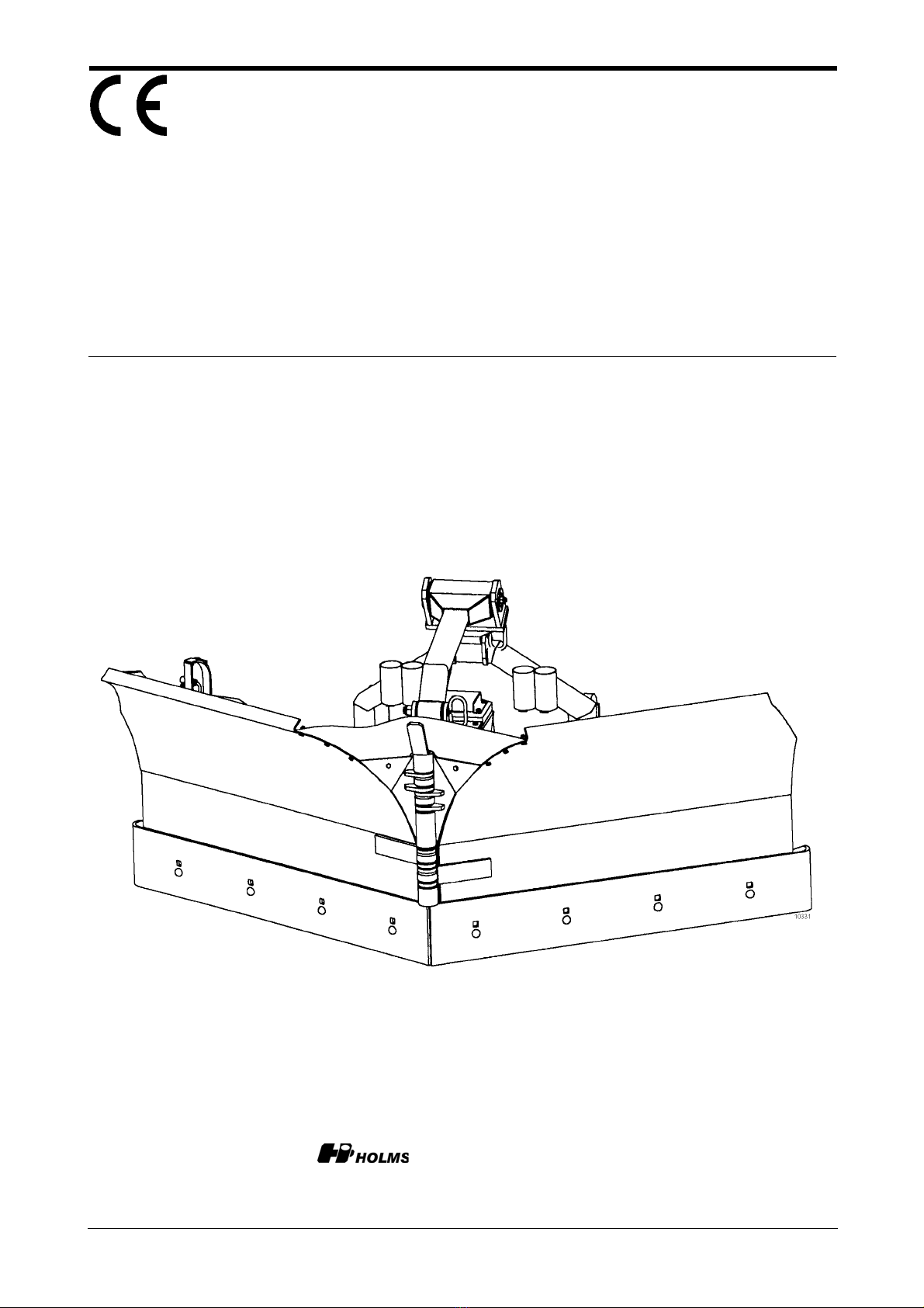
HOLMS KHV Specifications

© HOLMS INDUSTRI AB, ALL RIGHTS RESERVED 060405.
Operator instruction
Box 924 S-591 29 Motala Sweden + 46 141-22 41 00 ¬+ 46 141-22 41 90
Vee-plow
2,0/2,4m
From serial No: 5989.
KHV


KHV
© HOLMS INDUSTRI AB, ALL RIGHTS RESERVED 060405. 2
Content
Foreword ................................................ 3
Product facts........................................... 4
General information................................ 5
Coupling ................................................. 6
Setting .................................................... 6
Service and maintenance....................... 7
Important security aspects...................... 7
Connecting selector valve (extra equipment) ... 8

KHV
3© HOLMS INDUSTRI AB, ALL RIGHTS RESERVED 060405.
Foreword
This manual is intended to be a guide for correct use and main-
tenance of the plough. Study the manual before starting up and
operating or before any prevention maintenance is carried out.
Be confident with the equipment and all the instructions and
keep the manual so it will always be used before taking the
equipment into operation.
OBS! This manual is made to suit all our markets. There might
be some differences and if this is the case for you please do not
take notice.
We are continuously working on improvements and we re-
serve the right to make design changes and improvements
without notice.
The operator is obliged to:
• Look after ev. warning signs to be readable.
• See to that no unauthorized person uses the equipment or is
within the operating area during work or maintenance work
• Check that the carrier is appropriate to the attachment
(hydraulic flow, stability etc.)
When ordering spare parts or by other contacts with Holms or
your local dealer, always inform about the attachment type and
series No. This number you will find on the machine plate.
Do not make any modifications, changes, rebuilt work etc. which are
not approved by Holms Industri AB. We also ask you to pay
attention to spare parts not approved by us.

KHV
© HOLMS INDUSTRI AB, ALL RIGHTS RESERVED 060405. 4
Model KHV 2,0 KHV 2,4
Width (m) 2,0 2,4
Operating width by 30° angling (m) 1,8 2,2
Weight (kg) 450* 520*
Centre of gravity, measure A on drawing (mm) 506* 441*
Centre of gravity, measure B on drawing (mm) 216* 147*
Max. height excluding hooks (m) 1,06 1,06
Number of cutting edges (pcs) 22
Max hydraulic pressure (bar) 210 210
Centre of gravity
*) Valid with VME 4000 bracket, blades folded backwards.
A
B

KHV
5© HOLMS INDUSTRI AB, ALL RIGHTS RESERVED 060405.
General information
The snow plough KHV has two (2) individual adjust-able half-
blades hydraulically controlled. The control is carried out by
two (2) double-acting hydr. functions or by an electrically op-
erated selector valve for turning the half-blades.
The KHV-plough is equipped with spring-loaded cutt-ing edg-
es which are reversible.
Between the quick hitch attachment and the centre bracket the
pendulation unit (damping element) is mounted which allows
the plough to operate in floating position towards the ground.
The unit will also make the transport softer (plough lifted up
by the loading arms).
The tilting indicator mounted on the right hand side of the
plough will, when the two yellow markers are aligned, ensure
the right angle of the plough to the ground.
Adjustable support plates are standard on KHV 2,4 m, to be
used by snow removal on soft (no frozen) ground.
Selector valve Damping element Tilting indicator
Installation of selector valve
(optional equipment)
Left blade-half
(switch to the left)
Diagonal position
(switch straight up)
Right blade-half
(switch to the right)
Ground pressure indicator

KHV
© HOLMS INDUSTRI AB, ALL RIGHTS RESERVED 060405. 6
Coupling
The snow plough is connected to two (2) double acting hy-
draulic functions or one single function and electrical connec-
tion for the selector valve.
Make sure the couplings are free from dust!
Setting
1. The plough is lifted and the attachment bracket is tilted to
about 90° to the ground.
2. Lower the loader arms until the plough contacts the ground
and the tilting indicator markers are aligned.
3. Now the ground pressure can be set by the tilting function.
Normally the plough shall be operated tilted within its move-
ment area. This is when the ground pressure indicator yellow
markers are in line.
4. Operating with the plough in the middle of the movement
area will give the best ground follow, but temporarily the
ground pressure can be raised or reduced by tilting forwards
(raised) or backwards (reduced).
5. Only the tilting function is to be used for adjusting the
ground pressure. By using the lifting function the plough con-
tact is adjusted (see picture).
6. Check that the plough is moving free in all positions from
the wheel loader wheels.
Tilt to increase or
decrease ground pressure.
Lift or sink to
obtain the right
angling to ground.
Connect to the 3:rd
Connect to the 4:th
hydraulic function. hydraulic function.
Ground pressure indicator

KHV
7© HOLMS INDUSTRI AB, ALL RIGHTS RESERVED 060405.
Service and maintenance
After every use of the plough, check the wear of the cutting
edges and the bushings.
Once a season, after winter season, check also hoses, hydraulic
valves and cylinders. Check eventual wear and oil leakage.
Check the welded construction for eventual crack formations.
The cylinders shall be protected from surface rust by grease or
other corrosion protection.
Important safety regulations to be
noticed
• Be sure the loader is designed to carry / operate this attach-
ment with this weight.
• Be sure that unqualified persons are not close the operating
area during work or maintenance.
• Always use the quick coupling plugs and put the hose-ends
into the holders, when the plough is disconnected to avoid
dirt coming into the hydraulic system and to protect the
hoses.

KHV
© HOLMS INDUSTRI AB, ALL RIGHTS RESERVED 060405. 8
Alternative Connection of Selector Valve
(fixed mount of switch)
Plug-in connector 1500011 Plus voltage connected at ignition lock
Fuse
24 V / 5 Ampere
12 V / 10 Ampere
Switch 1500157
Cabling 242293
Earth on basic machine
This manual suits for next models
2
Table of contents