Hondex HE-777 User manual

OPERATIONS MANUAL
HE-777
ECHO SOUNDER / FISH FINDER

INTRODUCTION
DEFINITION OF SYMBOL MARK OF 【CAUTION FOR SAFETY】
: Incur the accident resulting in the death or serious wound
unless you keep the descriptions.
: Be in danger of incurring the accident resulting in the death or
serious wound unless you keep the descriptions.
: Be in danger or incurring the slight wound to human or damage
to other physical property unless you keep the descriptions.
・Do not reproduce a part or all of contents described on this manual without our
approval.
・Please understand that the unit may differ from contents described on this manual
partially due to change of specifications and so on.
・If you have questions on this manual, may we trouble you to inform us?
We thank you very much for purchasing HE-777.
Please be sure to read this operations manual carefully and understand what it describes
before you operate this unit in order to keep your safety.
After you read this manual, please keep it at the place where you will not lose or break and
so as to read soon when it necessary.
In case that you resell or transfer this unit, please give it to the new owner.
We will not be responsible for product liability (PL) law relating to damage to human or
physical property resulted from operation which is not described on this manual or wrong
operation.
DANGER
WARNING
CAUTION

CAUTION ON SAFETY (PLEASE MAKE SURE TO READ.) ............................... 1
HANDLING OF UNIT.......................................................................................... 1
HANDLING OF CABLES.................................................................................... 2
HANDLING OF TRANSDUCERAND WATER TEMPERATURE SENSOR ....... 3
CAUTION ON OPERATION ................................................................................... 4
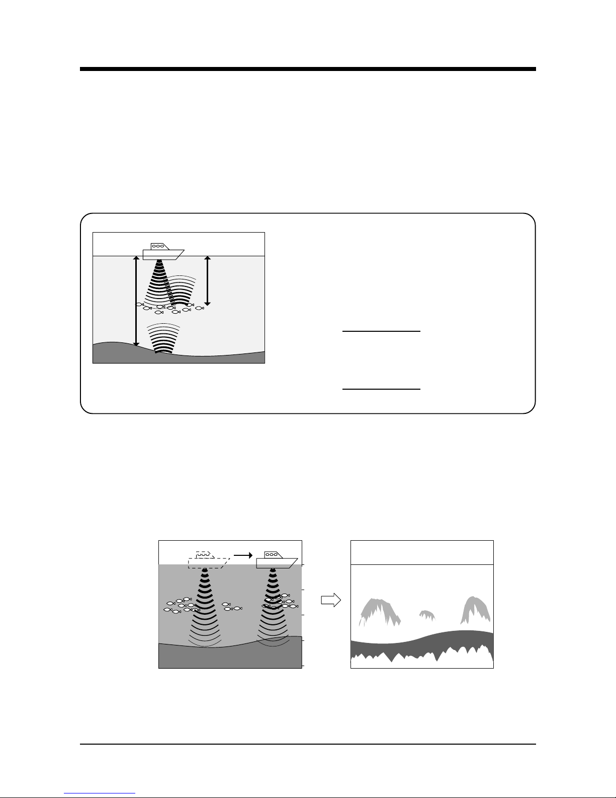
GENERAL INFORMATION OF ECHO SOUNDER/FISH FINDER ........................ 5
CHECK THE SUPPLIED UNIT AND ACCESSORIES........................................... 8
DEMENSIONAL DRAWING (DISPLAY) ................................................................ 9
INSTALLATION OF WATER TEMPERATURE SENSOR .................................... 10
CONNECTION WITH DISPLAY UNIT ...................................................................11
INSTALLATION OF THE UNIT............................................................................. 13
HOW TO SEE THE DISPLAY AND DESCRIPTIONS OF CONTROL KEYS ...... 15
POWER ON/OFF OF THE DISPLAY UNIT .......................................................... 16
POWER ON/OFF.............................................................................................. 16
TO USE FOR THE FIRST TIMEAFTER PURCHASING ................................. 17
ECHO SIMULATION......................................................................................... 17
TO SET THE SENSITIVITY.............................................................................. 18
TO SET THE DEPTH ....................................................................................... 20
TO CHANGE THE DISPLAY MODE................................................................. 22
SHIFT ............................................................................................................... 23
SETTING THE FUNCTION BY MENU ................................................................. 24
MENU LISTAND IT’S INDICATION METHOD................................................. 24
TO SELECT MENU ITEM................................................................................. 25
FUNCTIONS WHICH CAN BE SET BY MENU................................................ 26
SWEEP......................................................................................................... 26
AUTO GAIN.................................................................................................. 26
AUTO R/S..................................................................................................... 26
A-MODE ....................................................................................................... 26
SCALE LINE................................................................................................. 26
TEMP GRPH ................................................................................................ 26
ALARM ......................................................................................................... 27
CONTENTS

PICTURE...................................................................................................... 27
BACK GRD................................................................................................... 28
COLOR......................................................................................................... 28
EXP RATE .................................................................................................... 28
B/L EXP ........................................................................................................ 28
B/L POSI....................................................................................................... 28
DIGIT............................................................................................................ 28
DIG POSI ..................................................................................................... 28
SCALE UNIT ................................................................................................ 29
TEMP UNIT .................................................................................................. 29
TEMPADJ .................................................................................................... 29
C-ECHO ....................................................................................................... 29
STC .............................................................................................................. 29
PW REDUCER............................................................................................. 29
SPLIT SCR................................................................................................... 29
DISPLAY....................................................................................................... 30
RESET.......................................................................................................... 30
OPTIONS.............................................................................................................. 31
TROUBLE SHOOTING ........................................................................................ 32
SPECIFICATIONS ................................................................................................ 34

1
CAUTION ON SAFETY (PLEASE MAKE SURE TO READ.)
• High voltage is applied to the inside of unit.
No one besides authorized technician should disassemble or modify it.
Unless you keep it, the accident resulting in the electric shock will occur.
* Please be sure to consult with dealer when you want to repair.
DANGER
This section explains the important cautions in order to prevent the person who will use our product or other
persons from human damage or damage to their property.
HANDLING OF UNIT
• Do not install it simply.
It causes to the accident like human damage.
* Please be sure to install correctly according to descriptions on "Installation of the
unit" of this manual.
• Do not use the information displayed on the screen of unit for navigation directly.
It causes to the marine disaster.
* Please be sure to use the official marine charts for navigation judgement.
• Do not operate the unit when you operate the boat.
It causes to the marine disaster.
* Please be sure to operate it after due confirming the surrounding safety.
• Do not put the power on in the presence of flammable materials.
It causes to firing.
• Do not use the power supply besides the specified ones.
It causes to heating or firing.
WARNING

2
HANDLING OF CABLES
• Be sure to use the specified power supply cable.
It causes to heating or firing.
• Do not leave the power plug as it is while it is pulled out of the unit.
If the plug gets well, it causes to heating or firing due to short circuited.
• Be sure to wire in order to prevent the cables from interfering to operate boat.
If feet of crews or operating equipments are caught in cables, it causes to the acci-
dent.
* Do not put the heavy objects on cables or do not bend cables excessively.
• Do not disassemble or modify the cables.
It causes to heating, firing or electric shock.
• Do not use the damaged cables.
It causes to firing or electric shock.
WARNING
• Do not pull the cable when you pull out the plug.
It causes to firing or electric shock because the cable is broken.
* When you pull out the plug, be sure to have it in your hand and pull it.
CAUTION

3
HANDLING OF TRANSDUCER AND WATER TEMPERATURE SENSOR
• Work on the bard is too unstable and risky.
Installation and maintenance of transducer and water temperature sensor should be
done after you land and fix the boat.
Unless you keep it, human damage resulting in death or serious wound will occur.
DANGER
• Installation of the transducer or water temperature sensor inside the hull with adhe-
sive should be done while you ventilate well inside the boat.
Volatile gas from solvent or etc. causes to toxic symptoms.
• When you work using electric tools, please keep your hands dry.
If your hands are wet, it causes to electric shock.
• When you pull out or insert the plug of transducer or water temperature sensor,
please be sure to turn the power switch off.
It causes to electric shock.
• Perfect waterproof treatment should be done when you install the transducer or
water temperature sensor through the hull.
If waterproof is not sufficient, It causes to marine disaster because water come in.
WARNING

4
CAUTION ON OPERATION
When the engine starts to run, voltage of battery varies heavily. It may influence to the
unit.
Be sure to put the power switch of the unit off when you start to run the engine.
Be sure to put the power switch off when you start to run the engine!
Please operate the unit at 11~35VDC of power supply voltage.
Power supply should be 11~35VDC!
When temperature of the unit exceeds 70 C it causes to faulty. Please be more
careful to operate or store it under direct sun ray in the summer time and use it carefully
where it is in the shade as possible.
Avoid the place where it is high temperature!
Do not clean this unit with organic solution like thinner, alcohol or etc. as some
parts of the unit and panel are coated or made by plastic. In case it is too dirty, soak the
soft cloth in a synthetic detergent and clean with it after wringing well.
Prohibited to use the organic solution!
Water-spray on the unit causes to faulty. Install at the place where there is no water-
spray.
Be careful for water-spray!

5
GENERAL INFORMATION OF ECHO SOUNDER/FISH FINDER
THEORY OF ECHO SOUNDER/FISH FINDER
• Theory of echo sounder/fish finder is same as echo.
Ultrasonic pluses transmitted from the transducer into the water are reflected from fish school or the sea
bottom and then they are received by transducer.
Echo sounder/fish finder converts round-trip time between the time the ultrasonic wave is transmitted and
the time the reflected wave is received into distance and measures the depth. It displays size or density of
fish school, the outline of bottom or nature of bottom on the screen in different colors.
• Displayed image
Each time when image is sent by one line to the left, ultrasonic wave is transmitted and it’s reflected echo is
displayed on the right edge screen. By repeating this, image is formed.
0m
10m
20m
30m
40m
Round trip
0.5 sec.
Reflected wave
from fish school
Transducer
Reflected wave
from sea bottom
Round trip
1.0 sec.
The speed at which the ultrasonic wave propagates in
water is approximately 1,500mper second.
For example, in case of roundtrip time between
transmission and reception is 1 sec. to sea bottom and
0.5 sec. to fish school,
Distance to sea bottom......
1,500m (1 sec.)
2 (round-trip) = 750m
Distance to fish school......
750m (0.5 sec.)
2 (round-trip) = 375m

6
HOW TO DISTINGUISH THE FISH SCHOOL
• Importance is comparison between display of fish school and catch
It is possible to distinguish the fish sort by display of fish school to some extent. But even if fish sort is same,
it’s form making school is different according to difference of fishing ground and difference of time (day and
night, four seasons, variation of current).
The important thing to distinguish the fish sort is to know the sort according to their fishing ground or fishing
period and to find the useful point on the display by comparing between display of fish school and actual
catch.
HOW TO DISTINGUISH THE FISH VOLUME
• Fish volume can be distinguished by density and size of fish school
As the harder density the transmitted wave is reflected strongly, you can distinguish the density of fish
school according to the strength of reflected echo (that is, different color). Normally we tend to think the
larger fish school on the screen the most fish volume. But when fish school are located at the shallow depth
and the deep depth, fish school at the deep depth is displayed bigger than at the shallow depth. Because the
transmitted wave spreads wider as it goes deeper and the reflected wave spreads wider as it goes shal-
lower. As this result, the deeper depth becomes the wider the width of fish school becomes on the screen.
The important thing to distinguish the fish volume is to judge it according to size of fish school and the
strength of reflected echo (color) while you keep “the deeper fish school stays the bigger picture is dis-
played”in your mind.
Reflected
wave
Fish school B
Fish school A
Fish school A picture
(shallow)
Fish school B picture
(deep)

7
HOW TO DISTINGUISH THE NATURE OF BOTTOM
• There are different natures of bottom such as rock, sand, mud or etc.
In case you distinguish the nature of bottom, you judge from the thickness of bottom image and the situation
of second reflection.At the hard bottom like rock, reflection of transmitted wave becomes strong and bottom
image becomes thick and the second reflection becomes easily to appear. On the other hand, at the soft
bottom like sand or mud the reflection becomes weak and bottom image becomes thin and the second
reflection becomes hard to appear.
*Second reflection .......... Ultrasonic wave transmitted from transducer is reflected from sea bottom and
then it is reflected from both sea surface and bottom finally. In short, second re-
flection is image of two round-trips between sea surface and bottom.
Rock Sand or mud
Second reflection

8
CHECK THE SUPPLIED UNIT AND ACCESSORIES
Please check if all of the below-described items are packed when you use the unit for the first time.
Display Unit (with bracket) (1)
Operations manual (1)
Power Supply cable (1)
Fuse (10A) (1)
Disk Plate (6)
Screw for installing bracket (6)
M6X20
Screw

9
DEMENSIONAL DRAWING (DISPLAY)
<Drawing of holes for installing bracket>
Confirm no obstacles in this area.
11 11 11 11
100
170
276 308
100
8-φ6
6-φ9
278
254 340
335
200 120
: mm
A〜A
AA
AA

10
INSTALLATION OF WATER TEMPERATURE SENSOR
*Water temperature sensor is option.
•Work on the board is too unstable and risky.
Installation and maintenance of the water temperature sensor should be done after
you land and fix the boat.
Unless you keep it, human damage resulting in death or serious wound will incur.
DANGER
•Perfect water proof treatment should be done when you install the water tempera-
ture sensor through the hull.
Unless perfect, it causes to marine disaster due to inundation.
•When you work using electric tools, please keep your hands dry.
If your hands are wet, it causes to electric shock.
WARNING
<Installation of thru-hull water temperature sensor (TC02C)>
Water temperature sensor
Cork packing
Nut (2 pcs.)
Washer
FRP
Rubber packing
FRP
Perfect water-proof treatment should
be done at the joining position.

11
CONNECTION WITH DISPLAY UNIT
NMEA
(GGA,VTG)
Output
Transducer
Fuse Holder(10A)
Battery
(11~35V DC)
W (+) B (-)
Temp. Sensor
(Option)
5P
8P
6P
2P

12
1. Transducer (5-P)
2. Data In/Out (6-P)
3. Temperature (8-P)
4. Power Supply
Low F High F
32
1
5
4
1
2
3
4
5
1
2
3
4
5
6
7
1
2
3
456
1. GND
2. RXD-C
3. RXD-H
4. N.C.
5. TXD
6. DC12V out (max. 200mA)
1
2
3
4
5
6DATA OUT (RS232CLEVEL)
For EXTERNAL POWER
12V DC, 200mA (max.)
+
-
5V
1k
470Ω
12
3
4
5
678
1. N.C.
2. N.C.
3. N.C.
4. N.C.
5. N.C.
6. (+)
7. (-)
8. N.C.
12 1. (+) 11~35VDC
2. (-)

13
INSTALLATION OF THE UNIT
b. Installation in Landscape:After procedure 1 a, remove upper bracket by loosing 6 pcs. Pan head screws
with spring washers (M6X10)and install them on the side of display unit.
TO CHANGE DISPLAY STYLE, Call menu 3 and set Portrait, Portrait Reverse, Landscape or Landscape
Reverse.
After setting the unit, make sure to seal unused 6 holes by stickers to prevent damages from splash, etc.
Pan head screw
with spring washer
M6X10
Hexagon bolt
M8X20
<Procedure of installation>
1. <Selection of installation method> Unit is supplied in Portrait.
a. Installation in Portrait: Remove lower bracket by loosing 2 pcs. Hexagon bolts (M8X20) in front of the
bracket. Go to procedure 2.
•Do not install it simply.
If your hands are wet, it causes to electric shock.
It causes to the accident like wound.
* Please install correctly according to [Installation of the unit].
WARNING

14
4. <Installing the unit>
Put the unit on so that the rear of it’s upper bracket could fit in inner bento position at rear of lower bracket.
And then, fix the front of bracket with 2 pcs. hexagon bolt (M8X20).
Disk plate
X6
HEX. Bolt
M8X20
IMPORTANT NOTICE
When you install the unit on the ceiling, DO NOT USE pan head screws sup-
plied with the unit.
You must use hexagon bolts (bigger than M8X35) and install firmly.
Screw
M6X20
Bolt
M8X35
M8 HEX. Nut
8mm
Washer
8mm
S-Washer
3. <Putting the disk plate>
Put the supplied disk plates on six holes which are not used for installing the unit to prevent the water or
foreign substance from entering.
2. <Fixing the lower bracket>
After you decide the location to install the unit, fix the lower bracket with 6 pcs. screws M6X20 which are
supplied with the unit. Refer to [Dimensional drawing] for the position of holes.(Page 9)

15
REMARKS;
*1: To be shown when “NMEA(GGA, VTG)”is connected.
*2: To be shown when “Temp. Sensor (Option)”is connected.
*3: AR is shown when “Auto Range”is set.
AS is shown when “Auto shift”is set.
*4: “G AUTO”is shown when “Auto Gain”is set.
HOW TO SEE THE DISPLAY AND DESCRIPTIONS OF CONTROL KEYS
0
10
20
30
m
AR
N 34°43.356
E 137°37.456 341°
17.8N
50 G3.0 200 G3.0
18.0℃
17.5
4
Power/Brightness
Color Bar
*1 Latitude *1 Bearing *1 Boat Speed
SWEEP SPEED
*1 Longitude
*2 Water Temp.
*3 Auto Range Mark
Gain
Range
Depth Unit
*4 GAIN LEVEL
FREQUENCY
Mode
Menu
Shift
Depth
Fish Mark
FIRST
BOTTOM
ECHO
SECOND
BOTTOM
ECHO

16
POWER ON/OFF OF THE DISPLAY UNIT
POWER ON/OFF
•Please be sure to turn the power on after you start the engine of boat to prevent the
malfunction of unit or damage to memory contents.
CAUTION
MEMO:
When you use the unit for the first time, please read “TO USE FOR THE FIRST
TIME AFTER PURCHASING”
IMPORTANT NOTICE
The HE-777 is designed to use Hondex transducer.
If you use other brand transducer, please ask your local dealer to make sure it
works properly.
1. By rotating POWER & BRIGHT switch clockwise, a sound like
“piroro”sounds and power is turned on.
Adjust the brightness with rotating this switch.
POWER & BRIGHT switch
When you turn the power on, version No. of the system and
frequency are shown on the screen.
2. When you rotate this switch counterclockwise until a “Click”is
heard, power is turned off.
Table of contents
Popular Fish Finder manuals by other brands

Yachting
Yachting Naki 800C Installation and operation instructions

Garmin
Garmin Fishfinder 140 Declaration of conformity

Hummingbird Communications
Hummingbird Communications 300 Series Operation manual

Eagle
Eagle ULTRA 2 Installation & operating instructions

Hummingbird Communications
Hummingbird Communications 586C HD operating instructions

Humminbird
Humminbird Wide Paramount Operation manual