Hoopo HOOPOSENSE 502B1000-2A User manual

HOOPOSENSE
LORA DEVICE
502B1000-2A
User Manual
hoopo Systems Ltd.| 5 Ayalon Street, Ramat Hasharon

V 0.102 hoopo systems ltd. –hoopoSense Installation and connectivity
1
1Table of Contents
2General.................................................................................................................... 2
3System Overview...................................................................................................... 2
3.1 Mechanical ..................................................................................................................2
3.2 Electrical......................................................................................................................5
4Connectivity ............................................................................................................. 5
5Radio Compliance Statement.................................................................................... 5
6Battery Installation/replacement ............................................................................. 7
6.1 Top Cover Removal ......................................................................................................7
6.2 Batteries Installation....................................................................................................8
6.3 Top Cover replacement .............................................................................................. 11

V 0.102 hoopo systems ltd. –hoopoSense Installation and connectivity
2
2General
This document describes the hoopoSense, 502B1000-XA, installation instructions.
3System Overview
The hoopoSense devices are part of a tracking system that consists several FPX3 LoRa
gateways and a cloud based application server. The hoopoSense device transmits
various environmental and location parameters via LoRa or cellular communication
channels.
3.1 Mechanical
3.1.1 hoopoSense mechanical outline

V 0.102 hoopo systems ltd. –hoopoSense Installation and connectivity
3
Figure 1: hoopoSense with spacer outline drawing

V 0.102 hoopo systems ltd. –hoopoSense Installation and connectivity
4
Figure 2: hoopoSense with no spacer outline drawing

V 0.102 hoopo systems ltd. –hoopoSense Installation and connectivity
5
3.1.2 hoopoSense Installation Modes
The hoopoSense devices shall only be rigidly installed/embedded as part of various logistics
items; plastic pallets, various types of non-motorized ground support equipment, truck
trailers, large garbage containers, large building materials recycle containers etc.
Note: When installed on-top metal surfaces the device must be mounted on-top the supplied
plastic spacer.
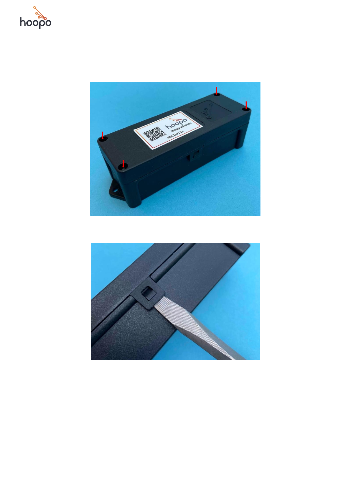
3.1.2.1 Plastic Pallets
Attach the hoopoSense devices with two 4 mm diameter screws. Do not exceed
the 3.0 Nm closing torque. The type of screws shall be defined by each pallet
manufacturer.
3.1.2.2 Large logistics items
Attach the hoopoSense devices on top of the supplied plastic spacer using two 4
mm diameter screws. Do not exceed the 3.0 Nm closing torque. The type of screws
shall be defined by each equipment manufacturer.
3.2 Electrical
The hoopoSense devices are powered by two or four primary AA batteries.
4Connectivity
The hoopoSense devices communicate via LoRa or cellular channels.
5Radio Compliance Statement
This device complies with FCC Rules Part 15 and with Industry Canada licence-exempt
RSS standard(s). Operation is subject to two conditions: (1) This device may not cause
harmful interference, and (2) this device must accept any interference that may be
received or that may cause undesired operation.
This equipment has been tested and found to comply with the limits for a Class B
digital device, pursuant to part 15 of the FCC Rules. These limits are designed to
provide reasonable protection against harmful interference in a residential
installation. This equipment generates, uses and can radiate radio frequency energy
and, if not installed and used in accordance with the instructions, may cause harmful
interference to radio communications. However, there is no guarantee that
interference will not occur in a particular installation. If this equipment does cause

V 0.102 hoopo systems ltd. –hoopoSense Installation and connectivity
6
harmful interference to radio or television reception, which can be determined by
turning the equipment off and on, the user is encouraged to try to correct the
interference by one or more of the following measures:
-Reorient or relocate the receiving antenna.
-Increase the separation between the equipment and receiver.
-Connect the equipment into an outlet on a circuit different from that to which the
receiver is connected.
-Consult the dealer or an experienced radio/TV technician for help.
Changes or modifications to this equipment not expressly approved by the party
responsible for compliance (hoopo Systems Ltd.) could void the user’s authority to
operate the equipment.
WARNING! To comply with FCC RF exposure compliance requirements, the device
should be located at a distance of at least 20 cm from all persons during normal
operation. The antennas used for this product must not be co-located or operated in
conjunction with any other antenna or transmitter.

V 0.102 hoopo systems ltd. –hoopoSense Installation and connectivity
7
6Battery Installation/replacement
6.1 Top Cover Removal
6.1.1 Remove the four top cover screws with a #1 phillips screwdriver.
6.1.2 Release both side latches using a flat screwdriver.

V 0.102 hoopo systems ltd. –hoopoSense Installation and connectivity
8
6.1.3 Remove the top cover.
6.2 Batteries Installation
6.2.1 Group the batteries in pairs using the supplied plastic tubes as depicted in the
following picture:
6.2.2 Please note the inscribed polarity on the bottom of the enclosure.

V 0.102 hoopo systems ltd. –hoopoSense Installation and connectivity
9
6.2.3 Place the nylon tab at the (+) pole.
6.2.4 Insert the bottom batteries pair; the (-) end first.
6.2.5 Press/slide down the batteries in-place as depicted in the following picture:

V 0.102 hoopo systems ltd. –hoopoSense Installation and connectivity
10
6.2.6 Place the top batteries pair; the (-) end first.
Note: Both batteries pairs are installed in parallel,
(-) on top (-) and (+) on top (+)
6.2.7 Press/slide down the batteries in place.
6.2.8 Pull out the nylon tab slider.

V 0.102 hoopo systems ltd. –hoopoSense Installation and connectivity
11
6.3 Top Cover replacement
6.3.1 Replace the top cover on the enclosure.
Note: The top cover is polarized and it fits in one
direction only as depicted in the following picture
6.3.2 Place and tight the top cover screws. Do not overtight.
Note: Tightening torque 1Nm maximum
6.3.3 In case one or both of the side latches are not fully engaged as depicted below:

V 0.102 hoopo systems ltd. –hoopoSense Installation and connectivity
12
6.3.4 Apply pressure at the center of the top cover until it “cliks” in place, if needed repeat
for both side latches.
Table of contents