Claas Trackmaster Guide

User & Installation Manual: CLAAS Trackmaster device Ver-6.1.4(DATE- 23/10/2015)
CLAAS Trackmaster
VTS USER & INSTALLATION MANUAL
Table of Contents
1. Installation - - - - - - - - - 2
i. Product Part list - - - - - - - 2
ii. Connector Wiring colors and their description - - 3
o6-Pin Connector Detail
iii. Precautions & Installation steps - - - - - 3
iv. Checks after installation and connection - - - 4
Description of LED Indicators - - - - - 4
oSmart LED (Green)
oGPS LED (Amber)
oGSM (Red)
v. New SIM card installation instruction - - - - 4
oPreparation
oInsertion of SIM card
2. Do’s and Don’ts- - - - - - - - - 5

User & Installation Manual: CLAAS Trackmaster device Ver-6.1.4(DATE- 23/10/2015)
1
Notes:

User & Installation Manual: CLAAS Trackmaster device Ver-6.1.4(DATE- 23/10/2015)
2
1.Installation
VTS device is pre-installed with national coverage GRPS activated SIM card. The request needs to be send for the
activation of services of SIM/ VTS device by submitting the required documents by dealer online at
http://claas.trackmaster.in/ and there by getting the User’s login and password to log on.
A. Product Part list
On receipt of VTS Device please check that all the parts are as describe below:
Product Part list for VTS DEVICE
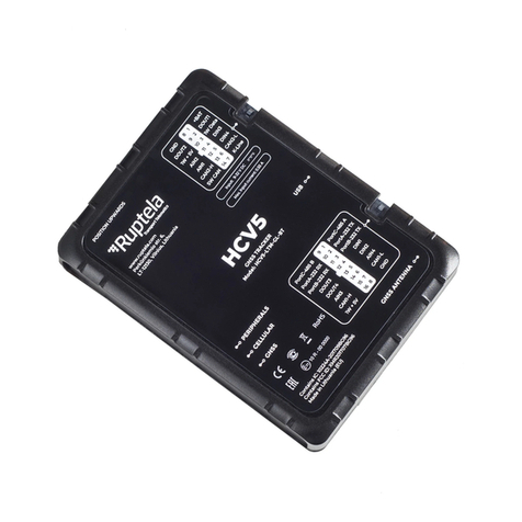
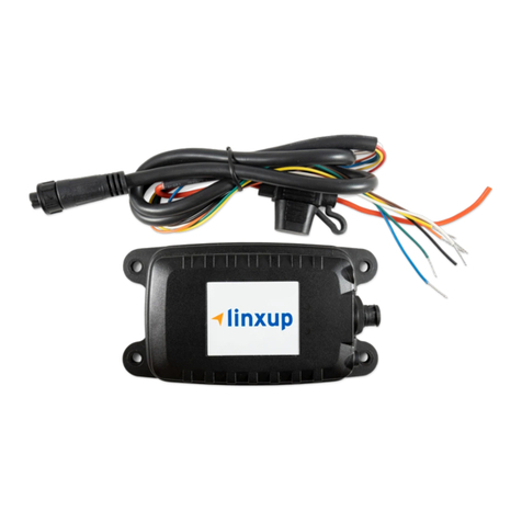
1. VTS DEVICE (CLAAS Trackmaster) with Device ID sticker
2. Grommet inserted on cable (Qty.1)
3. Assembled 6 PIN 250 SRS Tab housing
4. M6 Nut (Qty.2) and Washers (Qty.2)
5. User & Installation Manual

User & Installation Manual: CLAAS Trackmaster device Ver-6.1.4(DATE- 23/10/2015)
3
B. Connectors, Wire Colors & their Description
To connect the VTS device with machine wiring, there is a 6 PIN 250 SRS tab housing, the PIN out of the housing is as
shown below:
Wiring:
Connect the wiring correctly.
After all the wiring work has been completed and checked.
The unused electrical wire should be properly insulated.
C. Precautions & Installation steps:
National coverage GRPS activated SIM card is already installed in the VTS Device. The services of SIM card
need to be activated by submitting the documents to dealer and there by getting the user login and password.
Visually check the device and check as per part list, also check the availability of seal on one of the 8 screws.
M6 Nuts to be loose / unscrew before installation.
Check for the cut out on the front of panel for mounting the VTS device and place the device from outside.
Tighten the M6 Nuts after the insertion of washer, inside the panel.
Securely insert 6 PIN connector through the cut out and close the cut out with the grommet available on the cable.
Connect the VTS device connector with the 6 PIN recept housing available for device in machine wiring harness.

User & Installation Manual: CLAAS Trackmaster device Ver-6.1.4(DATE- 23/10/2015)
4
D. Checks after installation and connection:
Once the device has been installed & connected with machine wiring properly, the three LED on the device will start
blinking as describe below. Please note that it may take up to 20 minutes for all three LED to be “On”. Upon initial power
up, this is due to the searching of device for GPS/GSM signals, establishing itself on the GSM Cellular network and running
other diagnostics/ set-up routines.
1. Power (Green)
If LED is blinking: Device is powered on.
2. GSM LED (Red)
If LED is blinking with equal ON-OFF time: Device is still
registering to GSM, no SIM Card inserted or no network.
If LED while blinking with short ON and Long OFF time holds
on: Either GPRS service is not for more than 3-5 seconds
available or GPRS is not activated on SIM card.
If LED is blinking ON-OFF continuously e.g.2-3 times in 1 sec,
then devices is connected to HOST.
3. GPS LED (Amber)
If LED flashes: Device has acquired valid GPS signal.
If LED is OFF: GPS signal is either not available or the system is in process of acquiring the GPS signal
Though it is not recommended, But still if user wants to install the preferred GPRS activated SIM card, then
User has to communicate 10 Digit SIM number with APN to dealer to configure it with the VTS device. User
has to pay separately to new SIM service provider and has to ensure for the SIM services for proper working
of VTS Device
Request needs to be raised before installing the preferred GPRS activated SIM card to the VTS device.
It is recommended that trained personal at dealer do this activity.
E. New SIM card installation instruction:
Preparation
In order to install new SIM in VTS device properly, the following preparations should be carried
out:
• Prepare one operational GSM SIM Card. Make sure that the SIM Card:
—Can operate without PIN protection.
—Place SIM card in the mobile and check whether GPRS service is activated or not.
—Once GPRS service is activated, ask the local service provider for APN
—Communicate 10 Digit SIM number with APN to dealer to configure it with the VTS
device
Insertion of SIM in VTS Device
—Disconnect the vehicle battery and observe other Vehicle manufacturers
safety instructions.
—Before insertion of SIM card firstly remove the 6 pin connection from
machine electrical.
—Open the VTS Device from the back side, by opening 8 screws using
screw driver as shown.
—Now press the SIM slot slightly in the direction of Unlock shown.
—Now insert new SIM card and lock the slot by pressing the slot in lock
direction.
—Close the VTS device securely without damaging the seal used for water
proofing of the device and tighten the 8 screws using screw driver.

User & Installation Manual: CLAAS Trackmaster device Ver-6.1.4(DATE- 23/10/2015)
5
Do’s and Don’ts
1. Electrical Connections– Keep these in mind, else there could be danger of failure of VTS device or fire.
Check the power supply requirements in specification.
VTS device is meant to use with machine power supply only. Failing to do so might render the VTS device
inoperable and will void the warranty.
Do not connect the VTS device to the Battery of the vehicle until all the other loads/wires are
connected.
Avoid twisting or pinching wire.
Do not disconnect the VTS device from the Battery by pulling the wires.
Never open the VTS device yourself. It could risk electric short-circuit or damage the VTS device and
void the warranty.
2. Care & Maintenance:
Do not place any inflammable objects such as candles, cigarettes, oils & lubricants on the VTS Device.
Do not push any object into the slots, input sockets or the opening of the VTS Device.
Always observe VTS device before ignition and switch off on routine basis.
Do not use VTS device for any other purpose except for the machine Tracking/Management.
NOTE: - Removing or tempering the warranty sticker will void the warranty.
For any kind of assistance please contact: –
1. 18001026912 ( Toll-free)
2. 0172-5016501
Table of contents
