Hoppe AUDIO MINI Service manual

INSTALLATION INSTRUCTIONS / OWNER’S MANUAL:
AUDIO MINI
OFF-ROAD SOUND SYSTEM FOR KAWASAKI MULE PRO MODELS
www.hoppeindustries.com
22667 FM 15 Troup, TX 75789
(262) 552-2770

Revision B 2 of 21
Thank you for choosing the Hoppe Audio Mini off-road sound system. We hope you
enjoy the off-road sound system, and we ask that you follow these instructions very
closely. Doing so will save you time and ensure that your experience with the new Audio
Mini is a positive one.
We strongly suggest that you read the complete instructions before beginning the
installation process to eliminate the possibility of performing unnecessary work.
Having a safe and clean environment and using the proper tools is essential for a
successful installation.
It is critical that proper eye wear, ear protection, and protective clothing is worn
throughout the top installation.
When you receive your Audio Mini off-road sound system, please check to ensure that all
parts and hardware are included. If there are any parts missing or if you have any
questions concerning the system at this time call Hoppe at (262)-552-2770 Mon-Thur.
8am-5pm CST or Friday 8am -12pm CST. Or you can email us at
Hoppe reserves the right to change specifications, equipment, or designs at any time
without notice and without incurring obligation.

Revision B 3 of 21
TABLE OF CONTENTS
SECTION 1 –Tools Required............................................................................................ 4
SECTION 2 –About your Audio Mini sound system ......................................................... 4
2.1 Applicable Year Models:.......................................................................................... 4
2.2 Audio Equipment Details:......................................................................................... 4
2.3 Warranty: .................................................................................................................. 5
2.4 Care and Maintenance: ............................................................................................. 5
2.5 Warnings:.................................................................................................................. 6
SECTION 3 –Pre-Installation Inspection ......................................................................... 7
SECTION 4 –Installation.................................................................................................. 8

Revision B 4 of 21
SECTION 1 – Tools Required
Socket wrench set
Combination wrench set
Wire cutters
In addition to the above items, you may need shop supplies such as electrical tape, wire
ties, thread locking compound, etc.
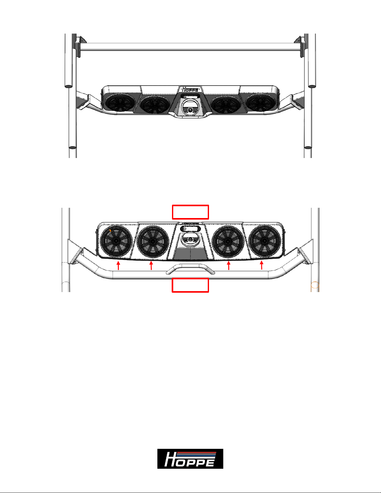
SECTION 2 – About your Audio Mini sound system
2.1 Applicable Year Models:
This Audio Mini off-road sound system is designed to fit the following Mule Pro models:
2015-2021 Mule Pro-FXT
2018-2021 Mule Pro-FXR
2016-2021 Mule Pro-FX
2016-2021 Mule Pro-DX
2016-2021 Mule Pro-DXT
This system is compatible with most front windshields (Plastic, Glass, and Flip-
Up) and roofs.
Modification to accessories that mount overhead near the front of the roll cage
such as rear view mirrors, wiper motors, etc. may not be compatible or may
require modification. Contact Hoppe customer service for questions.
2.2 Audio Equipment Details:
Your Audio Mini off-road sound system is powered by using
their marine series audio equipment. This equipment is designed to function in all
weather conditions with an IPX6 water resistance (powerful water jet) rating. The stereo
is specifically engineered to provide excellent sound quality and volume in an open air
enviroment so you can enjoy your music on the go.
To learn more details about your stereo system, you can access product information and
manuals for the stereo equipment here:
KMC2 receiver: https://www.kicker.com/kmc2
Speakers: https://www.kicker.com/41KM604W
You can feel free to crank up the volume without much worry of harming your system.
However, it is wise to use a little common sense. If you hear any distortion, back off a
little.
Use the equalizer settings in your KMC2 receiver to adjust the settings to your
preferences.

Revision B 5 of 21
2.3 Warranty:
Your Audio Mini comes equipped with a 1 year limited warranty covering the light, the
stereo equipment, and the fiberglass enclosure. The date of warranty coverage will be
determined by the registration date of the warranty card or online warranty registration.
http://www.motortrike.com/TrikeAccWarranty.aspx
If the warranty is not registered with Hoppe, the warranty period will begin when the
Audio Mini was shipped from Hoppe's factory.
2.4 Care and Maintenance:
Your off-road sound system does not require any maintenance other than an occasional
cleaning. To clean your audio system, simply hose off or power wash from a distance. If
needed, use a mild automotive soap and sponge or brush. Use common sense. Do not use
a high pressure power washer up close where it could cut, scar, or force water beyond the
design intent of the enclosure, light, or stereo equipment.
There is an inline fuse, close to the end of the chassis harness where it connects to the
battery. It can be accessed by pulling the cap off of the fuse holder. See Figure 1.
Figure 1: Fuse location.
Fuse 1: 15 amp mini fuse for light / radio receiver power.
There is also a 40 amp capacity skirted mini ignition relay built into the chassis harness
next to the inline fuse. See Figure 2.

Revision B 6 of 21
Figure 2: Chassis harness ignition relay
2.5 Warnings:
This off-road system adds up to 25 lbs. to your vehicle and is located up high on the roll
cage. This increases the vehicle’s center of gravity and changes the vehicle dynamics and
handling characteristics. Use extra caution as you learn the driving characteristics of your
vehicle with your new off-road sound system installed. High speed cornering, off camber
or side hill, acceleration, and braking performance will be negatively impacted by the
weight of the sound system.
Do not listen to your stereo at an uncomfortable volume for extended periods of time.
Potential hearing loss may result.

Revision B 7 of 21
SECTION 3 – Pre-Installation Inspection
Included in your off-road sound system are the following components:
Pre-assembled Audio Mini off-road sound system (All speakers and electronics
come preinstalled with interior wire harness.)
Chassis wire harness
Mounting brackets
Hardware bag
Zip ties
If any of the parts are missing, damaged, or you have any questions concerning them,
please call Hoppe at (262)-552-2770 Mon-Thur. 8am-5pm CST.
In addition to accounting for all of the parts that you should receive with the top, you
should inspect the vehicle in the following ways.
Ensure that the vehicle is equipped with the factory roll cage, and the roll cage has
not been bent out of shape in a roll over.
Make sure the vehicle does not have any aftermarket accessories that are
incompatible with the top.
Make sure the battery is in good condition and holds a charge.
Make sure the charging system is in good condition.

Revision B 8 of 21
SECTION 4 – Installation
1. Remove the factory bolts from the driver’s side of the front cross member. The
bolts will not be reused. Note: If you have a roof installed, remove the front
mounting bolts to gain access to the cross member bolts. See Figure 3 and
Figure 4.
Figure 3: Remove the factory cross member bolts.
Figure 4: Factory roof mounting bolt.
2. Place the bracket on the inside of the cross member. Use the supplied M10 bolts,
and loosely tighten them to allow for adjustment of the Audio Mini placement.
Verify correct orientation of the mounting bracket. See Figure 5.

Revision B 9 of 21
Figure 5: Mounting location of Audio Mini bracket. (Left side shown, right side similar)
3. Repeat Steps 1 and 2 for the passenger side bracket. Note: Reinstall your roof
fasteners after this step.
4. Using an assistant, hang the Audio Mini off-road sound system on the brackets
using the supplied ¼”-20 bolts and washers (loosely tightened). Note: The sound
system weighs up to 25 lbs. Since you will have to lift overhead and bolt each
end, it is helpful to have an assistant for this step. See Figure 6 and Figure 7.
Figure 6: Install the ¼”-20 bolts and washers to mount the Audio Mini to the brackets.

Revision B 10 of 21
Figure 7: Loosely install the sound system on the mounting brackets.
5. Tighten the 4 cross member bolts so that the Audio Mini is evenly spaced away
from the front cross member. See Figure 8.
Figure 8: Audio Mini evenly spaced away from cross member.
6. Tighten the 4 mounting bracket bolts after achieving the desired up-down position
relative to the brackets. Slots in the brackets allow up-down movement. See
Figure 9.
FRONT
REAR

Revision B 11 of 21
Figure 9: Up-down positioning of the Audio Mini.
7. Connect the chassis harness and the sound system harness by running the chassis
harness above the front cross member. See Figure 10.
Figure 10: Connect the chassis harness to the sound system.
8. Route the chassis harness, using the provided zip ties, on top of the roll cage (in
the roof recess) and down the down tube immediately behind the driver’s seat
towards the gap in the corner of the front seat as shown in Figure 11. Zip ties are
at the indicated arrow locations.

Revision B 14 of 21
Figure 13: Route the harness down the seat frame.
11. Secure the harness to the lower cross member in the open space under the floor,
behind the seat opening (next to the drive shaft). See Figure 14.
DOWN AND
BACK TO LOWER
CROSS MEMBER
LOWER CROSS
MEMBER IN
OPEN SPACE
UNDER FLOOR

Revision B 15 of 21
Figure 14: Secure the harness to the lower cross member.
12. You must tilt the bed to gain access to the engine compartment for the following
steps.
13. Remove the battery compartment cover by unlatching the front and side latches.
See Figure 15.
FROM
SEAT
FRAME
BACK TO
ENGINE
COMPARTMENT

Revision B 16 of 21
Figure 15: Remove the battery compartment cover.
14. Route the harness from the lower cross member into the engine compartment,
then run the black and red wires (with fuse holder) into the battery compartment
through the hole in the black rubber divider. The orange wire will be routed
further back in the next steps. Ensure clearance of the drive shaft by pulling the
harness tight when securing it with a zip tie. See Figure 16, Figure 17, and Figure
18.
Figure 16: Compartment overview under rear seat and/or bed.
LATCHES
FRONT
REAR
RUBBER
COMPARTMENT
DIVIDER
BATTERY COMPARTMENT

Revision B 17 of 21
Figure 17: Red and black harness wires go into the battery compartment.
Figure 18: Secure the harness to the factory loom.
RED AND BLACK
LOOMED WIRES
INTO THE BATTERY
COMPARTMENT
HARNESS
PULLED TIGHT
FROM LOWER
CROSS MEMBER
ZIP TIED
TO LOOM
ROUTE ORANGE
WIRE UNDER
THIS BUNDLE
FRONT
FRONT
REAR
REAR

Revision B 18 of 21
15. Connect the ring terminal on the RED wire of the Audio Mini harness to the +
POST of the battery. See Figure 19.
Figure 19: Red harness wire battery connection.
16. Connect the ring terminal on the BLACK wire of the Audio Mini harness to the –
POST of the ground block. See Figure 20.
Figure 20: Black harness wire ground connection.
RED WIRE TO
+ POST
BLACK WIRE TO
- POST

Revision B 19 of 21
17. Route the orange (accessory) harness wire along the rear frame as shown in
Figure 21.
Figure 21: Orange (accessory) harness wire routing.
18. Secure the orange wire from the Audio Mini harness to the factory wire loom as
shown in Figure 22. Then plug the male bullet connector on the end of the orange
wire into the mating female bullet connector on the brown wire with white stripe.
The female bullet connector on the Kawasaki OEM harness is located under a
rubberized plastic cover. Note: Secure any loose wire so that it will not get
caught on any moving parts (gas struts, bed, etc.).
ZIP TIED
TO LOOM
UNDER
FRAME TO
OUTSIDE

Revision B 20 of 21
Figure 22: Orange (accessory) harness wire routing and connection.
19. Reinstall the battery compartment cover and tighten both latches. Lower the bed,
place the rear seat back into position (if applicable), and lock the bed into position
with both side latches.
20. You are now ready to enjoy the music and lighting provided by your Audio Mini
off-road sound system. Basic operation works as follows:
Turn the vehicle ignition switch on to power up the stereo system. (You
must press the power button for first time connections or if the power was
previously turned off manually.)
Press the mode button on the stereo receiver to select the input source
from AM/FM radio or Bluetooth.
Hold the mode button to access additional menus.
The dome light can be used with or without the vehicle’s ignition switch
on. Press the on/off switch to activate the light.
Warning: Extended use of the dome light or stereo without the
vehicle’s charging system functioning will deplete the battery and the
engine may not start.
To learn about the more advanced features and operation of your stereo, visit the
Kicker website links found in SECTION 2 –About your Audio Mini sound system
of this document.
Thank you for choosing Hoppe Audio Mini off-road sound system for you Kawasaki
Mule Pro UTV. We hope you enjoy your new sound system and lighting. We invite you,
in your travels, to stop by our manufacturing plant in Troup, Texas, for a factory tour and
to meet the people who designed and manufactured your Audio Mini off-road sound
system. This will also give you an opportunity to check out our sister company
ZIP TIE
LOOSE
WIRE
Other manuals for AUDIO MINI
8
Table of contents
Other Hoppe Car Receiver manuals
Popular Car Receiver manuals by other brands

Somogyi Elektronic
Somogyi Elektronic SAL VB 6100 instruction manual

Nakamichi
Nakamichi NA100R instruction manual

Pioneer
Pioneer DEH-4800FD owner's manual

BOSSCO
BOSSCO BV8968 user manual

Sony
Sony CDXM60UI - Marine CD Receiver MP3/WMA/AAC... Installation/connections

Panasonic
Panasonic CQC5405U - AUTO RADIO/CD DECK-MULTI LANG Service manual