HORNER APG HE-X24-AS Series User manual

MAN0814-01 02 AUG 2006 PAGE 1
No part of this publication may be reproduced without the prior agreement and written permission of Horner APG, Inc.
Information in this document is subject to change without notice.
1 INTRODUCTION
The Switching Power Supply Series offers compact, lightweight, highly efficient and reliable units that are
DIN Rail-mounted or mounted on the back of a panel. Short circuit and overload protection is provided as
well as over-heat protection to stop output when the temperature reaches 275°[135°C]). Units also have
soft-start functionality to limit peak current and voltage during startup. Two special functions are
provided: Remote Control Switching (RPS) and Uninterruptible Power Supply (UPS).
The following models are included in the Switching Power Supply Series.
Table 1 – Switching Power Supply Series Models
Model Part Number Simple Part Number* Description
HE-X24-AS AS 24 VDC / 1.5 A
HE-X24-AL AL 24 VDC / 3 A
* Part Numbers are simplified in this document for easier reading.
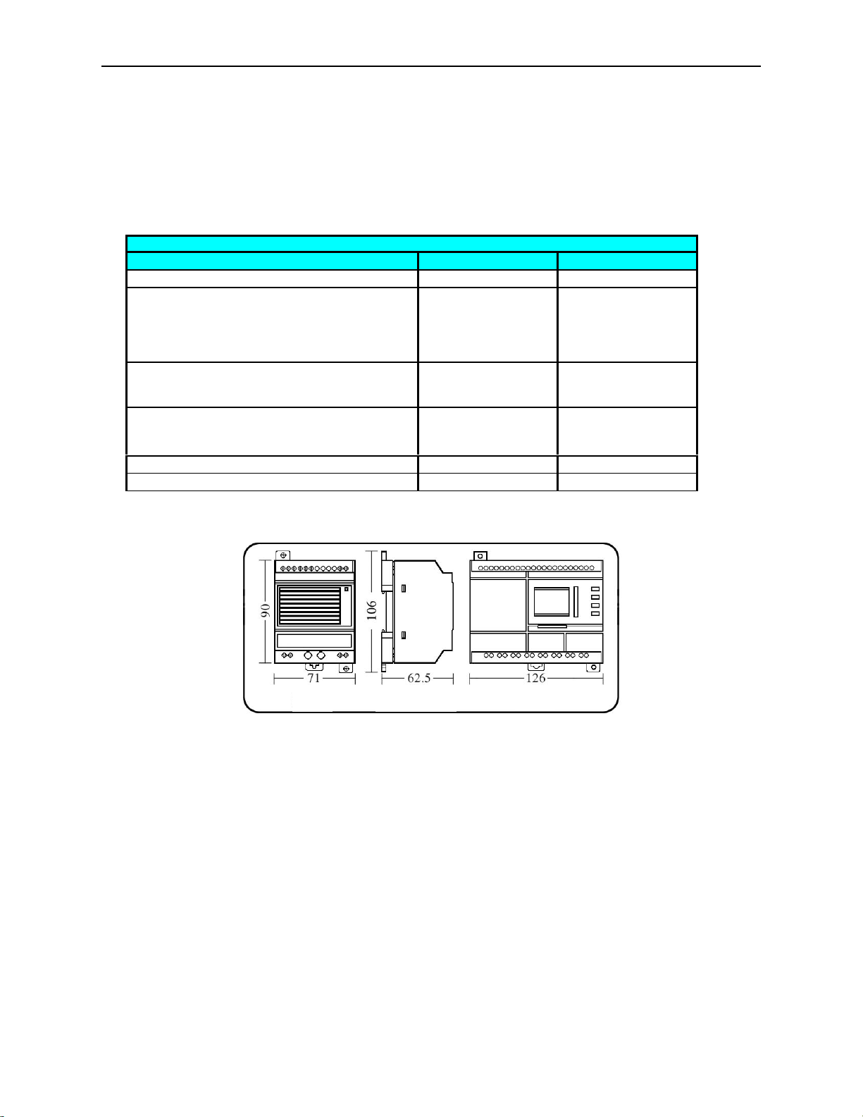
Figure 1 – Two Ways to Mount AS / AL
Table 2 – Specifications for AS / AL
Parameter AS AL Parameter AS AL
Output Voltage 24 VDC Operation Temperature -13°to 158°(-25°to +70°C)
Current 1.5 A 3.0 A Efficiency > 75%
Input Voltage 100-240 VAC /
140-340 VDC Insulation Voltage
Endurance > 1.5 kV
Ripple Voltage
Tolerance Range 85 –264 VAC /
120-370 VDC Filter EMI Filter Condenser
Input Frequency 47 – 63 Hz Output Voltage
Fine Adjustment Range
(Using Potentiometer V) -5% to +10%
Output Voltage
Stability ±0.5% Overload Protection 105% to 135%
Ripple 150 mVp-p
Switching Power Supply Series
HE-X24-AS
HE-X24-AL
The AS / AL can be mounted on a DIN Rail or
mounted on the back of a panel.
Note: For mounting on the back of a panel, use
the two tabs that are shipped with the unit.
DIN Rail Mounting Clip Mounting Tab
Mounting Tab

PAGE 2 02 AUG 2006 MAN0814-01
No part of this publication may be reproduced without the prior agreement and written permission of Horner APG, Inc.
Information in this document is subject to change without notice.
.
2 Dimensions
Dimensions vary according to how the AS or AL is mounted. The AS and AL share some common
dimensions. Refer to Table 3 and the drawings shown in Figure 2 to determine correct dimensions.
Table 3 – Dimensions for AS / AL
Parameter Drawing Value
Height AS / AL 2.46 in (62.5 mm)
Width
(No mounting tabs and no DIN Rail Clip) AS / AL
(Note: Shown only in
AS drawing, but it
applies to AS / AL
units.)
3.54 in (90 mm)
Width
(Includes mounting tabs when mounting in
back of a panel)) AS / AL 4.17 in (106 mm)
Width
(Includes DIN Rail Mounting Clip) AS / AL
(Note: Dimension
not shown.) 3.86 in (98 mm)
Length AS 2.80 in (71 mm)
Length AL 4.96 in (126 mm)
Figure 2 – Dimensions
AS AS / AL AL

MAN0814-01 02 AUG 2006 PAGE 3
No part of this publication may be reproduced without the prior agreement and written permission of Horner APG, Inc.
Information in this document is subject to change without notice.
3 GENERAL OPERATION
Figure 3 – General Operation
1. For output and short circuit protection, ensure that the Switch/Short Circuit jumper block is
installed and properly seated.
2. Adjust the current (using Potentiometer A) for maximum load current protection by rotating fully
clockwise.
3. Connect the power (100-240 VAC / 140-340 VDC).
4. Adjust the output voltage (using Potentiometer V) to 24 VDC.
5. Connect the load to the output terminal.
4 Remote Control Switching (RPS) Function
The RPS function allows the control of the output voltage using a remote control switch.
Figure 4 –RPS Function
1. Remove the Switch/Short Circuit jumper block. Wire an external switch (K1).
2. Adjust the current (using Potentiometer A) for maximum load current protection by rotating fully
clockwise.
Current Adjust
(Pot. A) Voltage Adjust
(Pot. V)
ON Switch /
Short Circuit
Jumper Block
Power
100-240 VAC /
140-340 VDC
A
C/DC Input
Ground
+24 VDC
Storage
Battery
Warning: Be sure to wire the load
observing the proper
polarity on the unit and
ensure that the
maximum working
current is ≤3 A.
Current
Adjust
(Pot. A)
Voltage
Adjust
(Pot. V)
External Switch
(K1)
Power
100-240 VAC /
140-340 VDC
A
C/DC Input
Ground
+24 VDC
Storage
Battery
Load

PAGE 4 02 AUG 2006 MAN0814-01
No part of this publication may be reproduced without the prior agreement and written permission of Horner APG, Inc.
Information in this document is subject to change without notice.
.
3. Connect the power (100-240 VAC / 140-340 VDC).
4. a. Close switch (K1) to turn power ON from the supply.
b. Adjust the output voltage (using Potentiometer V) to 24 VDC.
c. Open switch (K1) to turn power OFF from the supply.
5. Connect the load to the output terminal.
7. Close switch k1 to turn power ON from the supply.
5 Uninterruptible Power Supply (UPS) Function
The UPS function uses an external battery to provide power in the event that the power source stops
providing power or is interrupted.
Figure 5 –UPS Function
1. For output and short circuit protection, ensure that the Switch/Short Circuit jumper block is
installed and properly seated.
2. Adjust the current (using Potentiometer A) for maximum load current protection by rotating fully
clockwise.
3. Connect the power (100-240 VAC / 140-340 VDC).
4. Adjust the output voltage (using Potentiometer V) to 24 VDC.
5. Disconnect the AC/DC power wire.
6. Wire switch K2 and fuse wire F1 and the External Battery
7. Re-connect the power (100-240 VAC / 140-340 VDC).
Note: If the battery voltage is over +24 VDC, adjust Potentiometer V to the applicable voltage.
Note: When using the UPS function, the output is normally powered by the line voltage. When the line
and battery are connected, the battery will be charged. If the line voltage is removed, the output is
supplied by the battery. Switch K2 allows the battery to be disconnected, and fuse F1 protects the battery
side of the circuit. The battery current is ≤3 A.
Warning: Be sure to wire the load observing the proper polarity on the unit and ensure that the
maximum working current is ≤3 A.
Warning: Be sure to wire switch K2 and fuse wire F1 and the External Battery observing the proper
polarity on the unit.
Current
Adjust
(Pot. A)
Voltage
Adjust
(Pot. V)
ON Switch /
Short Circuit
Jumper Block
Power
100-240 VAC /
140-340 VDC
A
C/DC Input
Ground
+24 VDC
Load
F1
K2
External
Battery

MAN0814-01 02 AUG 2006 PAGE 5
No part of this publication may be reproduced without the prior agreement and written permission of Horner APG, Inc.
Information in this document is subject to change without notice.
6 Using RPS and UPS Functions Simultaneously
To use both the RPS and UPS functions simultaneously, follow the steps described in the RPS section
(page 3) and the UPS section (page 4) in this document.
Figure 6 – Using RPS and UPS Function
7SAFETY
When found on the product, the following symbols specify:
Warning: Consult user documentation. Warning: Electrical Shock Hazard.
WARNING: To avoid the risk of electric shock or burns, always connect the safety (or earth)
ground before making any other connections.
WARNING: To reduce the risk of fire, electrical shock, or physical injury it is strongly
recommended to fuse the power. Be sure to locate fuses as close to the source as possible.
WARNING: Replace fuse with the same type and rating to provide protection against risk of
fire and shock hazards.
WARNING: In the event of repeated failure, do not replace the fuse again as a repeated failure
indicates a defective condition that will not clear by replacing the fuse.
WARNING: Only qualified electrical personnel familiar with the construction and operation of
this equipment and the hazards involved should install, adjust, operate, or service this
equipment. Read and understand this manual and other applicable manuals in their entirety
before proceeding. Failure to observe this precaution could result in severe bodily injury or
loss of life.
Power
100-240 VAC /
140-340 VDC
A
C/DC Input
Ground
+24 VDC
Load
F1
External Battery
K

PAGE 6 02 AUG 2006 MAN0814-01
No part of this publication may be reproduced without the prior agreement and written permission of Horner APG, Inc.
Information in this document is subject to change without notice.
.
•All applicable codes and standards need to be followed in the installation of this product.
•For I/O wiring (discrete), use the following wire type or equivalent: Belden 9918, 18 AWG or
larger.
Adhere to the following safety precautions whenever any type of connection is made to the module.
•Connect the green safety (earth) ground first before making any other connections.
•When connecting to electric circuits or pulse-initiating equipment, open their related breakers. Do
not make connections to live power lines.
•Make connections to the module first; then connect to the circuit to be monitored.
•Route power wires in a safe manner in accordance with good practice and local codes.
•Wear proper personal protective equipment including safety glasses and insulated gloves when
making connections to power circuits.
•Ensure hands, shoes, and floor are dry before making any connection to a power line.
•Make sure the unit is turned OFF before making connection to terminals. Make sure all circuits
are de-energized before making connections.
•Before each use, inspect all cables for breaks or cracks in the insulation. Replace immediately if
defective.
8 TECHNICAL SUPPORT
For assistance and manual updates, contact Technical Support at the following locations:
North America:
(317) 916-4274
www.heapg.com
email: techsppt@heapg.com
Europe:
(+) 353-21-4321-266
www.horner-apg.com
email: [email protected]
This manual suits for next models
4
Table of contents
Popular Power Supply manuals by other brands

YOSHINO
YOSHINO B2000 SST user manual

Dynojet
Dynojet Power commander V installation instructions

Extron electronics
Extron electronics PS 1215 C installation guide

Omega Engineering
Omega Engineering DIN-RAIL DRN-PS-750 Operator's manual

Sens
Sens PowerCab 2 Installation & operation manual

Simplex
Simplex 4008-9801 installation instructions