4
www.prbx.com PBSE10273731A 2023.10-11
Specifications are subject to change without notice.
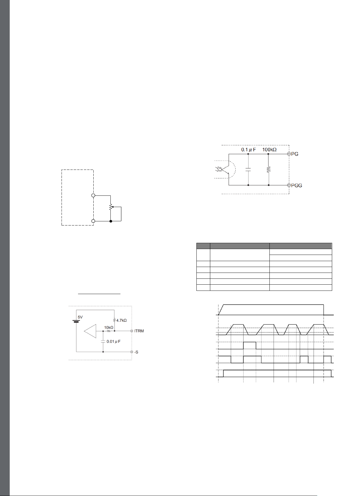
3.5 Output ripple and ripple noise measurement
The specified ripple and ripple noise are measured by the method
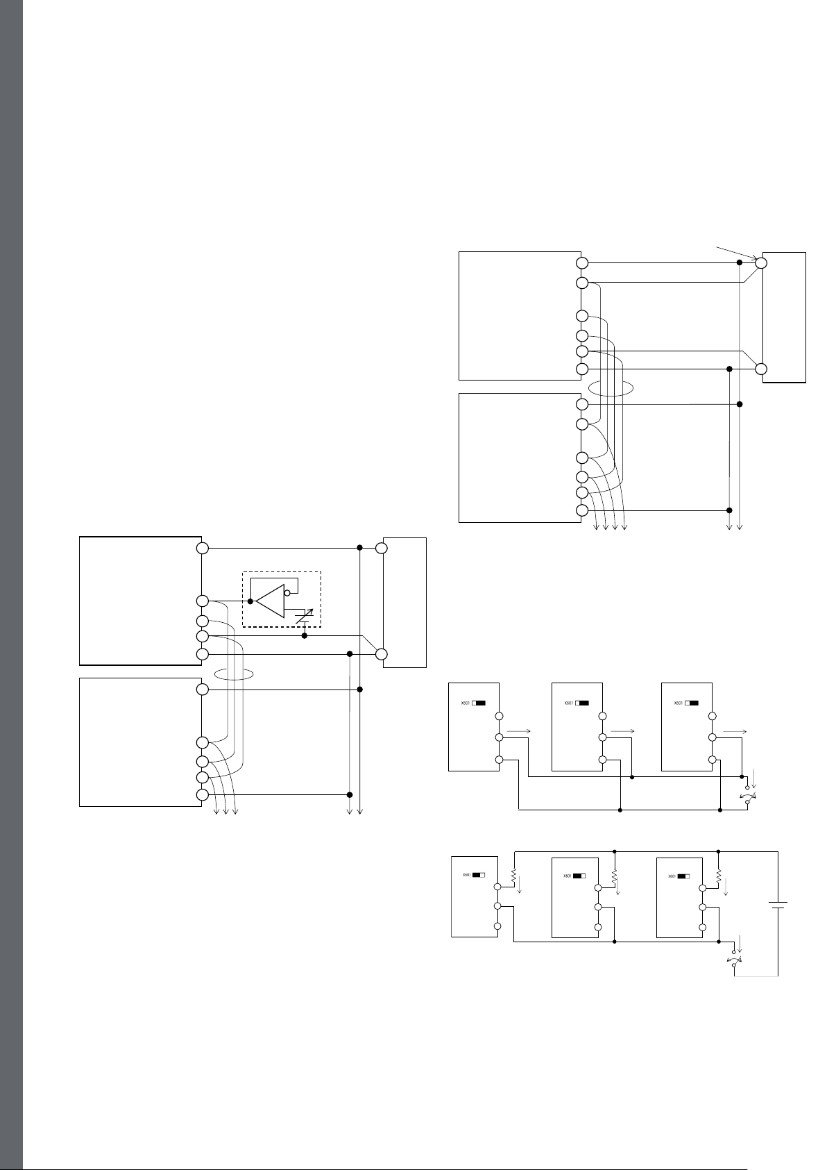
shown in Fig.3.3.
Fig.3.3 Method of Measuring Output ripple and ripple noise
Remarks:
- When the ambient temperature is lower than -20°C, the output ripple
may become unstable during heating up.
4. Functions
4.1 Input voltage range
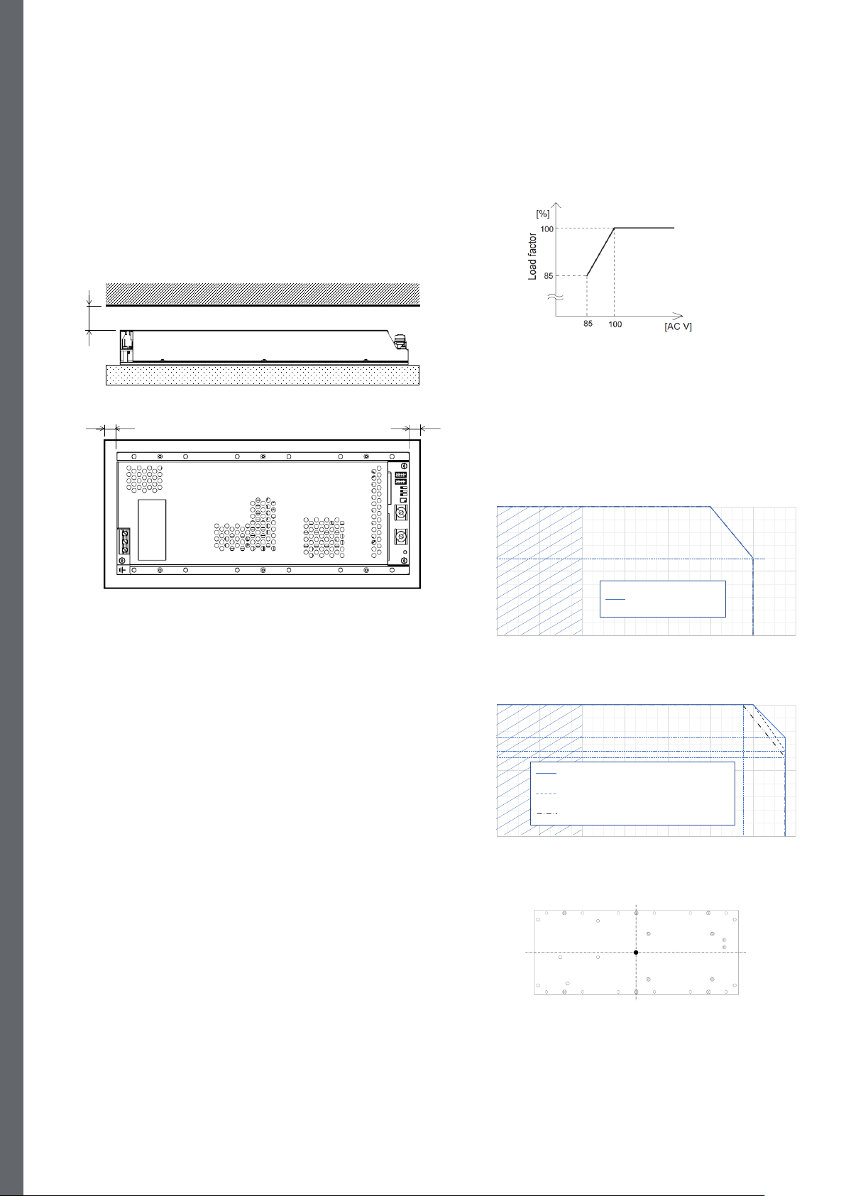
The unit operates with an input voltage range between 85 - 305 VAC.
The voltage range for a valid safety approval is 100 - 277 VAC
(50/60Hz).
Remarks:
- Be aware that use of voltages other than those listed above may
result in the unit not operating according to specifications or may
cause damage or dangerous situations. Avoid square waveform input
voltage, commonly used in UPS and inverters.
4.2 Inrush current limiting
There is a built-in inrush current limiting circuit.
If a switch is needed on the input side, select one that can withstand
the input inrush current.
The thyristor technique is used in the inrush current limiting circuit.
Avoid repeatedly turning the power ON/OFF within a short period of
time, operates the inrush current limiting becomes inoperative.
When the input power is turned on, the primary inrush current and
secondary inrush current will be generated due to the thyristor
technique used for the inrush current limiting circuit.
4.3 Over current protection
The over current protection is built in and comes into effect when
drawing over 105% of the rated current.
The over current protection prevents the unit from short circuit and
over current condition. The unit automatically recovers when the fault
condition is cleared.
When the output voltage drops at over current, the average output
current is reduced by hiccup operation of the unit.
4.4 Over voltage protection
The over voltage protection circuit is built in. If the over voltage
protection circuit is activated, shut down the input voltage, wait a
certain time and turn on the AC input again to recover the output
voltage.
The recovery time is 10 seconds or more.
Remarks:
- Note that devices inside the unit might fail if voltage of higher than
rated output voltage is applied to output terminal. This could happen
when the user tests the over voltage performance of the unit.
- With option -O (Active ORing) circuit disconnects the output from the
external voltage. Therefore, over voltage protection will not be
activated. Therefore, it is not possible to test over voltage performance
for an option -O unit by applying external voltage.
4.5 Thermal protection
When the baseplate temperature exceeds the maximum temperature,
thermal protection will be activated and shut down the output.
When the thermal protection is activated, turn off the input voltage and
eliminate all the overheating conditions. To recover the output voltage,
let the unit cool down before turning on the input voltage again.
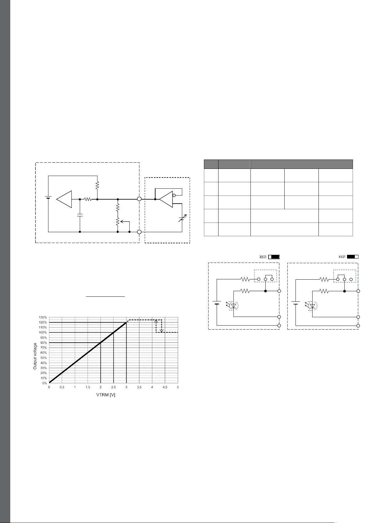
4.6 Output voltage adjustment
The output voltage can be adjusted by means of either the built-in
potentiometer (R513) or by applying an external voltage source.
(a) Adjustment by built-in potentiometer
To increase output voltage, turn R513 clockwise. To decrease the
output voltage, turn it counter clockwise.
The output voltage adjustment range by R513 is shown below.
Model Output
Number Voltage adj.
OFD1200A12-N 4.2 –14.4VDC
OFD1200A28-N and -NO 9.8 - 33.6VDC
OFD1200A48-N and -NO 16.8 - 57.6VDC
OFD1200A65-N 22.8 –78.0VDC