Hornet 725T User manual

Model 725T
Installation Guide
© 2002 Directed Electronics, Inc. Vista, CA N725T 4-02
®

2© 2002 Directed Electronics, Inc. Vista, CA
Bitwriter™, Code Hopping™, DEI®, Doubleguard®, ESP™, FailSafe®, Ghost Switch™, Learn
Routine™, Nite-Lite®, Nuisance Prevention Circuitry®, NPC®, Revenger®, Silent Mode™, Soft Chirp®,
Stinger®, Valet®, Vehicle Recovery System®, VRS®, and Warn Away® are all Trademarks or Registered
Trademarks of Directed Electronics, Inc.
table of contents
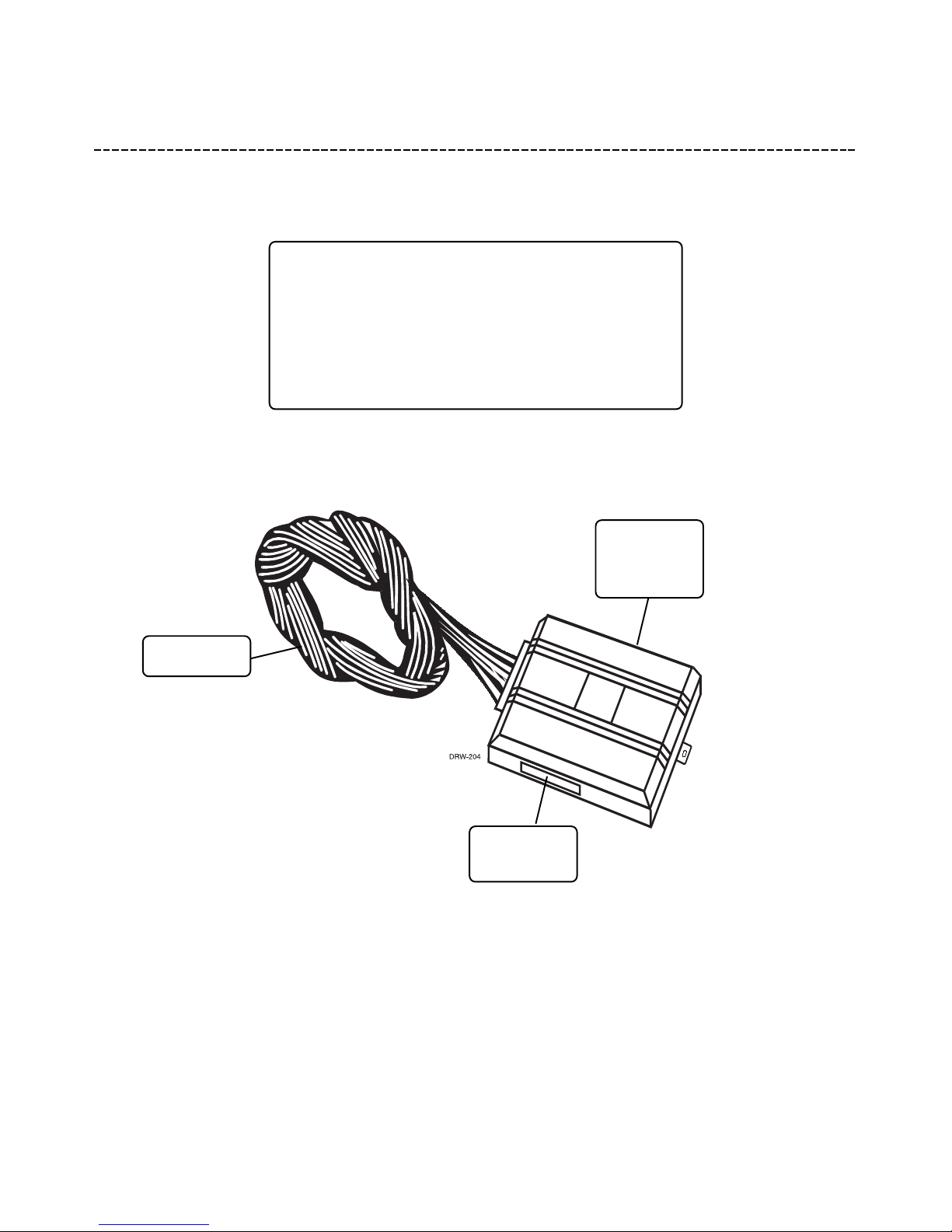
what is included . . . . . . . . . . . . . . . . . . . . . 3
installation points to remember . . . . . . . . . . 4
deciding on component locations . . . . . . . . . 4
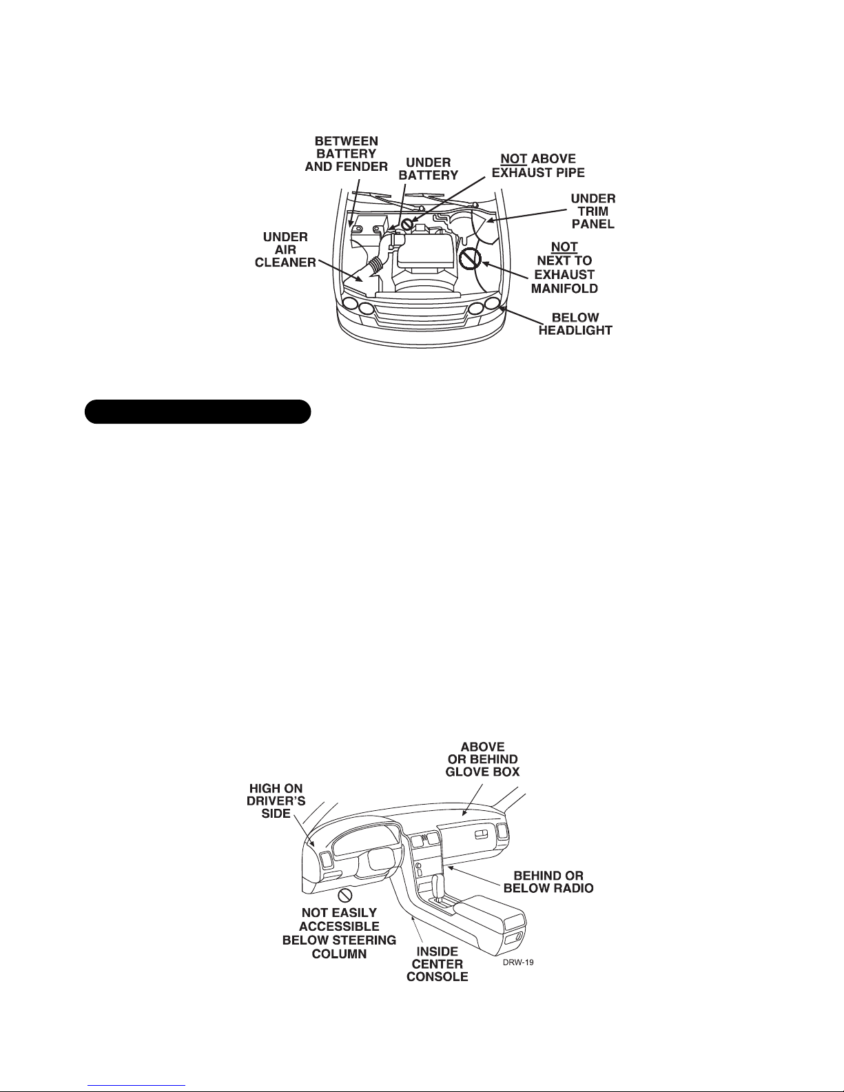
locations for the siren . . . . . . . . . . . . . . . . 4
locations for the control module . . . . . . . . . 5
on-board stinger doubleguard shock sensor . . 6
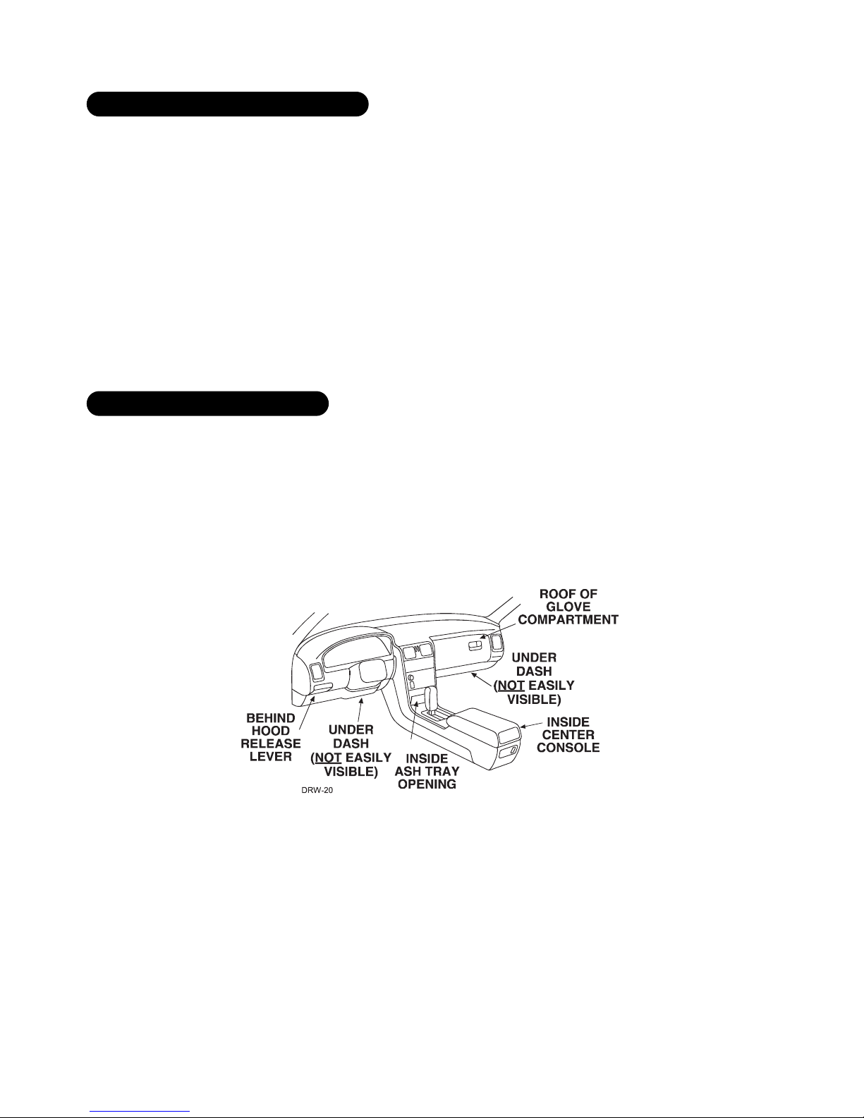
locations for valet/program switch . . . . . . . . 6
locations for the status LED . . . . . . . . . . . . 6
locations for the optional starter kill relay. . . 7
finding the wires you need . . . . . . . . . . . . . . 7
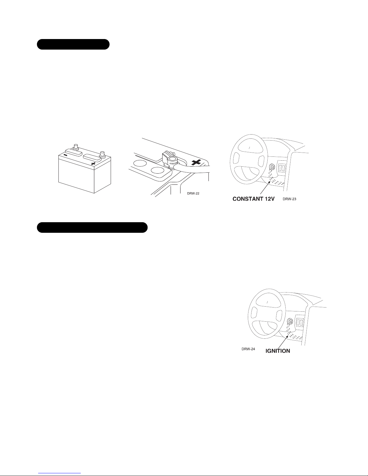
obtaining constant 12V . . . . . . . . . . . . . . . 7
finding the 12V switched ignition wire . . . . . 8
finding a (+) parking light wire . . . . . . . . . . 8
finding the door pin switch circuit. . . . . . . . 9
finding the starter wire . . . . . . . . . . . . . . 10
making your wiring connections . . . . . . . . . 10
primary harness (H1), 12-pin connector . . . . 11
primary harness wire connection guide . . . . . 12
on-board stinger doubleguard shock sensor . . 16
bypassing sensor inputs . . . . . . . . . . . . . . . 16
harness 2, (-) door lock outputs . . . . . . . . . 17
type A door locks . . . . . . . . . . . . . . . . . . 18
type B door locks . . . . . . . . . . . . . . . . . . 19
type C door locks . . . . . . . . . . . . . . . . . . 20
type D door locks . . . . . . . . . . . . . . . . . . 21
type E door locks . . . . . . . . . . . . . . . . . . 22
type F door locks . . . . . . . . . . . . . . . . . . 23
type G door locks . . . . . . . . . . . . . . . . . . 24
type H door locks . . . . . . . . . . . . . . . . . . 25
transmitter/receiver learn routine™ . . . . . . . 26
two-vehicle operation with single transmitter 27
operating settings learn routine™ . . . . . . . . 28
feature menu . . . . . . . . . . . . . . . . . . . . . . 29
feature descriptions . . . . . . . . . . . . . . . . . 30
nuisance prevention circuitry (NPC™) . . . . . . 31
valet mode . . . . . . . . . . . . . . . . . . . . . . . . 32
table of zones . . . . . . . . . . . . . . . . . . . . . . 32
troubleshooting . . . . . . . . . . . . . . . . . . . . 33

© 2002 Directed Electronics, Inc. Vista, CA 3
what is included
■The control module (see diagram)
■Two remote transmitters P/N 491T
■A on-board Stinger®Doubleguard®shock sensor
■A Revenger®Soft Chirp®siren
■The plug-in status LED
■The plug-in Valet®/Program switch
3-pin, 2-wire
door lock
harness
Stinger
Doubleguard
Shock Sensor
Adjustment
Primary
Harness (H1)

4© 2002 Directed Electronics, Inc. Vista, CA
installation points to remember
Do not disconnect the battery if the vehicle has an anti-theft-coded radio. If equipped with an air bag, avoid
disconnecting the battery if possible. Many airbag systems will display a diagnostic code through their warning
lights after they lose power. Disconnecting the battery requires this code to be erased, which can require a trip
to the dealer.
Before beginning the installation:
■Check with the customer on status LED location.
■Remove the domelight fuse. This prevents accidentally draining the battery.
■Roll down a window to avoid being locked out of the car.
After the installation:
■Test all functions. The “Using Your System” section of the Owner's Guide is very helpful when testing.
■When testing, don’t forget that this system is equipped with Nuisance Prevention Circuitry™(NPC™). NPC can
bypass trigger zones, making them appear to stop working. See the Nuisance Prevention Circuitry section.
deciding on component locations
Some things to remember about mounting the siren:
■Keep it away from heat sources, such as radiators, exhaust manifolds, turbochargers, and heat shields.
■Mount it where a thief cannot easily disconnect it, whether the hood is open or shut. Both the siren and its
wires should be difficult to find. This usually involves disguising the wire to look like a factory harness.
■We recommend against grounding the siren to its mounting screws. Instead, we recommend running both the
red and black wires into the passenger compartment and grounding to one common point for all devices.
After all, both wires are the same length and come already bonded together. Whenever possible, conceal your
wires in the factory harnesses or in the same style loom as the factory.
■When possible, place the siren on the same side of the vehicle as the control module, where its wires will
reach the control module’s wires without extending them. Always run the wires through the center of a
grommet, never through bare metal!
■Point the siren down so water does not collect in it.
locations for the siren

© 2002 Directed Electronics, Inc. Vista, CA 5
Some good siren locations:
Some things to remember about where to mount the control module:
■Never put the control module in the engine compartment!
■The first step in hot-wiring a vehicle is removing the driver's side under-dash panel to access the starter and
ignition wires. If the control module is placed just behind the driver's side dash it can easily be disconnected.
■When mounting the control module, try to find a secure location that will not require you to extend the har-
nesses’ wires (they are 1.5 meters long). Keep it away from the heater core (or any other heat sources) and
any obvious leaks.
■The higher the control module is in the vehicle, the better the transmitter range will be. If you put the control
module under a seat or inside a metal dashboard, range will suffer, and you may wish to add a DEI®542T
Range Extending Antenna (available separately).
Some good control module locations:
locations for the control module

6© 2002 Directed Electronics, Inc. Vista, CA
How the control module is mounted is the most important factor in determining the performance of the on-board
shock sensor. We recommend two methods for mounting the control module:
■Using double-sided tape or hook-and-loop fastener to mount to a trim panel or an air duct, or
■Wire-tying to a wire harness.
If mounting the control module where it cannot be easily accessed for adjustment, hook-and-loop fastening tape
(such as Velcro) is recommended for ease of removal for future adjustments.
NOTE: In many vehicles, screwing the control module to metal will result in poor sensitivity, espe-
cially at the rear of the vehicle.
IMPORTANT! When the vehicle is delivered, please show the user where this switch is located and
how to disarm the system with it.
Ensure that the location you pick for the switch has sufficient clearance to the rear. The switch should be well
hidden. It should be placed so passengers or stored items (such as items stored in a glove box or center console)
cannot accidentally hit it. The switch fits into a 9/32-inch hole.
This system features Remote Valet®. The user can enter and exit Valet®Mode without having to reach for the
Valet®/Program switch. Directed introduced this feature so that Valet/Program switch location was less critical in
day-to-day use. As long as it can be reached to disarm without a transmitter, easy access to this switch is not
vital.
locations for valet/program switch
on-board stinger doubleguard shock sensor

© 2002 Directed Electronics, Inc. Vista, CA 7
Things to remember when positioning the Status LED:
■It should be visible from both sides and the rear of the vehicle, if possible.
■It needs at least 1/2" clearance to the rear.
■It is easiest to use a small removable panel, such as a switch blank or a dash bezel. Remove it before drilling
your 9/32" hole.
■Use quick-disconnects near the LED wires if the panel is removable. This lets mechanics or other installers
remove the panel without cutting the wires.
If the optional starter kill relay or its connections are immediately visible upon removal of the under-dash panel,
they can easily be bypassed. Always make the relay and its connections difficult to discern from the factory
wiring! Exposed yellow butt connectors do not look like factory parts, and will not fool anyone! For this reason,
routing the starter kill wires away from the steering column is recommended.
finding the wires you need
Now that you have decided where each component will be located, you will need to find the wires in the vehicle
that the security system will be connected to.
IMPORTANT! Do not use a 12V test light to locate these wires! Use a digital multimeter for all
testing.
locations for the optional starter kill relay
locations for the status LED

8© 2002 Directed Electronics, Inc. Vista, CA
We recommend two possible sources for 12V constant: the (+) terminal of the battery, or the constant supply to
the ignition switch. Always install a fuse within 12 inches of this connection. If the fuse also will be powering
other circuits, such as door locks, a power window module, a Nite-Lite®headlight control system, etc., fuse
accordingly.
IMPORTANT! Do not remove the fuse holder on the red wire. It ensures that the control module has its
own fuse, of the proper value, regardless of how many accessories are added to the main power feed.
The ignition wire is powered when the key is in the run or start position. This is because the ignition wire powers
the ignition system (spark plugs, coil) as well as the fuel delivery system (fuel pump, fuel injection computer).
Accessory wires, on the other hand, lose power when the key is in the start position to make more current avail-
able to the starter motor.
How to find (+)12V ignition with your multimeter:
1. Set to DCV or DC voltage (12V or 20V is fine).
2. Attach the (-) probe of the meter to chassis ground.
3. Probe the wire you suspect of being the ignition wire. The steering
column harness or ignition switch harness is an excellent place to
find this wire.
4. Turn the ignition key switch to the run position. If your meter reads
(+)12V, go to the next step. If it doesn’t, probe another wire.
5. Now turn the key to the start position. The meter display should stay steady, not dropping by more than a
few tenths of a volt. If it drops close to or all the way to zero, go back to Step 3. If it stays steady at (+)12V,
you have found an ignition wire.
finding the 12V switched ignition wire
obtaining constant 12V

© 2002 Directed Electronics, Inc. Vista, CA 9
Most vehicles use a (+) parking light circuit. In these vehicles, an optional 8617 relay is required to interface
with the light flash feature. The (+) parking light wire is often found near the switch. Many cars have the switch
built into the turn signal lever, and in these cars the parking light wire can be found in the steering column. The
same wire is often available in the kick panel or running board.
NOTE: Many Toyotas, as well as many other Asian vehicles, send a (-) signal from the switch to a
relay. The relay then sends (+)12V to the bulbs. Whenever you have difficulty finding a (+) parking
light wire near the switch, simply test the wires at any switch or control panel which is lit by the
instrument panel lighting. Remember, you need a (+) parking light wire that does not vary with
the dimmer setting.
How to find a (+) parking light flash wire with your multimeter:
1. Set to DCV or DC voltage (12V or 20V is fine).
2. Attach the (-) probe of the meter to chassis ground.
3. Probe the wire you suspect of being the parking light wire. Usually, the area near the headlight/parking light
switch is an excellent area to start, as is the kick panel.
4. Turn on the parking lights. If your meter shows (+)12V, turn off the parking lights and make sure it goes back
to zero.
5. If it does return to zero, turn the parking lights back on and, using the dash light dimmer control, turn the
brightness of the dash lights up and down. If the meter changes more than a volt when using the dimmer,
look for another wire. If it stays relatively close to (+)12V, you have found your parking light wire.
NOTE: Vehicles that use a (-) signal from the switch to the factory relay may be interfaced directly.
These vehicles do not require an optional relay.
finding a (+) parking light wire

10 © 2002 Directed Electronics, Inc. Vista, CA
The best places to find the door pin switch wire are:
■At the pin switch: When testing at the pin switch, check the wire to ensure that it “sees” all the doors. Often,
the passenger switch will cover all the doors even if the driver’s switch will not.
■At the dome light: This may not be your best choice if the vehicle has delayed domelight supervision, but it
will work in many Hondas, or any vehicle with completely diode-isolated pin switches.
Once you have determined the wire color, the easiest place to connect to the wire is often at the kick panel, at
the windshield pillar, or in the running board. When an easy location is not available, running a wire to the dome-
light itself is often the best solution.
How to find a door pin switch trigger wire with your multimeter:
1. Set to DCV or DC voltage (12V or 20V is fine).
2. In most Fords, fasten the (-) probe of the meter to chassis ground. In most other cars, fasten the (+) probe
of your meter to (+)12V constant.
3. Probe the wire you suspect of being the door trigger wire. If the meter reads (+)12V when any door
is opened, you have found a trigger wire.
NOTE: Make sure the wire you use “sees” all the doors! Some newer GM vehicles lack standard-type
pin switches. The dome light in these vehicles is turned on when the door handle is lifted. These
usually have a blue/white or white wire coming out of the door into the kick panel which will
provide a (-) trigger for all doors. Some GM vehicles (some Cavaliers, Grand Ams, etc.) have a yellow
wire coming out of the door which provides a (+) door trigger.
The starter wire provides 12V directly to the starter or to a relay controlling the starter. In some vehicles, it is
necessary to power a cold start circuit. A cold start circuit will test exactly like a starter circuit, but it does not
control the starter. Instead, the cold start circuit is used to prime the fuel injection system for starting when the
vehicle is cold.
How to find the starter wire with your multimeter:
1. Set to DCV or DC voltage (12V or 20V is fine).
2. Attach the (-) probe of the meter to chassis ground.
3. Probe the wire you suspect of being the starter wire. The steering
column is an excellent place to find this wire. Remember you do not
need to interrupt the starter at the same point you test it. Hiding
your starter kill relay and connections is always recommended.
4. Turn the ignition key switch to the start position. Make sure the car
is not in gear! If your meter reads (+)12V, go to the next step. If it doesn’t, probe another wire.
finding the starter wire
finding the door pin switch circuit

© 2002 Directed Electronics, Inc. Vista, CA 11
5. Cut the wire you suspect of being the starter wire.
6. Attempt to start the car. If the starter engages, reconnect it and go back to Step 3. If the starter does not
turn over, you have located the correct wire.
making your wiring connections
Before making your connections, plan how your wires will be routed through the vehicle. For instance, the yellow
ignition input, the red 12V constant input, and the orange ground-when-armed output (for the optional starter
kill relay) will often be routed together to the ignition switch harness. In order to keep the wiring neat and make
it harder to find, you may wish to wrap these wires together in electrical tape or conceal them in tubing similar
to what the manufacturer used.
There are two acceptable ways of making a wire connection - solder connections and crimp connectors. When
properly performed, either type of connection is reliable and trouble-free. Regardless of whether you solder your
connections or you use mechanical-type crimp-on connections, ensure that all connections are mechanically
sound and that they are insulated.
Cheap electrical tape, especially when poorly applied, is not a reliable insulator. It often falls off in hot weather.
Use good-quality electrical tape or heat shrink.
■Never twist-and-tape the wires together without soldering.
■Never use “fuse taps”, as they can damage fuse box terminals.
If you use tapping connectors such as 3M T-Taps (not to be confused with Scotch-Locks), avoid using them in
higher-current applications (constant 12V, ground, etc.). Some tapping connectors are inferior in quality and
should be avoided.

12 © 2002 Directed Electronics, Inc. Vista, CA
primary harness (H1), 12-pin connector
______
______
______
______
______
______
______
______
______
______
______
______ RED/WHITE (-) 200 mA CHANNEL 2 VALIDITY OUTPUT
RED (+) CONSTANT POWER INPUT
BROWN (+) SIREN OUTPUT
YELLOW (+) SWITCHED IGNITION INPUT, ZONE 5
BLACK (-) CHASSIS GROUND INPUT
VIOLET (+) DOOR TRIGGER INPUT, ZONE 3
BLUE (-) INSTANT TRIGGER INPUT, ZONE 1
GREEN (-) DOOR TRIGGER INPUT, ZONE 3
BLACK/WHITE (-) VALET/PROGRAM BUTTON INPUT
WHITE/BLUE (-) 2V LED OUTPUT
WHITE (-) 200 mA LIGHT FLASH OUTPUT
ORANGE (-) 500 mA ARMED OUTPUT
H1/1
H1/2
H1/3
H1/4
H1/5
H1/6
H1/7
H1/8
H1/9
H1/10
H1/11
H1/12

© 2002 Directed Electronics, Inc. Vista, CA 13
primary harness wire connection guide
This wire supplies a (-)500 mA ground as long as the system is armed. This output ceases as soon as the system
is disarmed. This wire can be used to control the optional Directed 8618 starter kill relay. The 8617 relay assem-
bly may also be used as shown in the diagram below.
NOTE: If connecting the orange wire to control another module, such as a Directed 529T or 530T
window controller, a 1 amp diode (type 1N4004) will be required. Insert the diode as shown below.
IMPORTANT! Never interrupt any wire other than the starter wire.
The unit supplies a (-)200mA output that can be used to flash the parking lights of the vehicle. If the vehicle uses
a relay to drive the parking lights, this wire may be connected directly to the control wire for the factory relay. In
most cases, however, a relay will be required to drive the parking lights, as shown below.
H1/2 WHITE (-) light flash output
H1/1 ORANGE (-) ground-when-armed output

14 © 2002 Directed Electronics, Inc. Vista, CA
Connect this wire to the blue wire on the status LED. Then connect the red wire of the status LED to (+) 12V
constant fused.
Connect to the gray wire on the Valet/program switch. The black wire on the Valet/program switch should be
connected to chassis ground.
If the door switch wire you found is (-) when the door is open, connect the green wire to it. If the door switch
wire you found is (+) when the door is open, use the violet wire instead.
IMPORTANT! Test to make sure this wire "sees" all doors!
This input will respond to a (-) input with an instant trigger. It is ideal for hood and trunk pins and will report
on Zone 1. If connecting several inputs to this wire, they should be diode isolated as shown.
H1/6 BLUE (-) instant trigger input
H1/5 GREEN (-) door trigger or H1/7 VIOLET (+) door trigger input
H1/4 BLACK/WHITE valet/program switch input
H1/3 WHITE/BLUE (-) 2V LED output

© 2002 Directed Electronics, Inc. Vista, CA 15
Connect this wire to a clean, paint-free sheet metal location (driver kick panel) using a factory bolt that DOES
NOT have any vehicle component grounds attached to it. A screw should only be used when in conjunction with
a two-sided lock washer. Under dash brackets and door sheet metal are not acceptable ground points. It is rec-
ommended that all security components be grounded at the same location.
Connect this wire to an ignition wire. This wire must show (+) 12V with the key in the run position and during
cranking.
IMPORTANT! Make sure that this wire cannot be shorted to the chassis at any point.
H1/9 YELLOW (+) ignition input
H1/8 BLACK (-) chassis ground connection
H1/7 VIOLET (see H1/5 GREEN)

16 © 2002 Directed Electronics, Inc. Vista, CA
Connect this to the red wire of the Revenger™ siren. Connect the black wire of the siren to (-) chassis ground,
preferably at the same point you grounded the control module’s H1/8 BLACK wire.
Before connecting this wire, remove the supplied fuse. Connect to the battery positive terminal or the con-
stant 12V supply to the ignition switch as described in the Finding the Wires You Need section of this guide.
NOTE: Always use a fuse within 12 inches of the point you obtain (+)12V. Do not use the 10A fuse
in the harness for this purpose. This fuse protects the module itself.
When the system receives the code controlling Channel 2 for longer than 1.5 seconds, the red/white wire will
supply an output as long as the transmission continues. This is often used to operate a trunk/hatch release or
other relay-driven function.
IMPORTANT! Never use this wire to drive anything but a relay or a low-current input! The transis-
torized output can only supply 200 mA of current. Connecting directly to a solenoid, motor, or other
high-current device will cause it to fail.
H1/12 RED/WHITE channel 2, 200mA (-) output
H1/11 RED (+)12V constant power input
H1/10 BROWN (+) siren output

© 2002 Directed Electronics, Inc. Vista, CA 17
on-board stinger doubleguard shock sensor
There is a dual-stage shock sensor inside the control unit. Adjustments are made via the rotary control as indi-
cated in the diagram. Since the shock sensor does not work well when mounted firmly to metal, we do not
recommend screwing down the control module. The full trigger of the on-board shock sensor reports Zone 2. (See
Table of Zones section of this guide.)
NOTE: When adjusting the sensor, it must be in the same mounting location that it will be after
the installation is completed. Adjusting the sensor and then relocating the module requires read-
justment.
bypassing sensor inputs
There are times when you need to temporarily bypass all sensor inputs to the unit, such as when remote start-
ing the vehicle. Anytime an auxiliary channel output is used, all inputs are bypassed for five seconds. During the
five second bypass period, ground can be supplied to the H1/6 Blue wire without triggering the unit. When the
five second bypass period ends, if the unit sees ground on the H1/6 Blue wire, all trigger inputs except the door
trigger input will remain bypassed until five seconds after ground is removed from the BLUE wire. This can be
done using the status output of a Directed Electronics remote engine starting unit as shown in the following
diagram:

18 © 2002 Directed Electronics, Inc. Vista, CA
harness 2, (-) door lock outputs
______
______
______
These wires provide (-)200mA pulses that are used to control electric door locks. Most common interfaces are
described in this section.
IMPORTANT! If you mistake a Type C direct-wired system for a Type A positive-pulse system, the
module will be damaged!
The system can control Type A door locks, with the addition of a 451M Door Lock Relay module or two relays.
The switch will have three wires on it, and one will test (+)12V constantly. The others will alternately pulse
(+)12V when the switch is pressed to the lock or unlock position.
If you cannot get to the switch, and you find a set of wires that pulses (+)12V alternately on lock and unlock,
you must take care to ensure that it is not a Type C direct-wire system.
Here is a test: Cut the wire which pulses (+)12V on lock, and then operate the switch to unlock.
■If all doors unlock, the vehicle uses type A system.
■If you lose all door lock operation in both directions, you are operating the master switch in a Type C system.
■If you lose all door lock operation of one or more, but not all motors stop operating, and other doors still
work, you have cut a wire leading directly to one or more motors. You must instead find the actual wires
leading to the switch.
Many domestically-made GM vehicles use Type A locks. However, many more GM vehicles are Type C than in pre-
vious years. The full-size pickups (1989-up), many of the S10 Blazers, the Corvette, '95 Cavalier/Sunfire 1993
and newer, Camaro/Firebird all use Type C door locks, and cannot be controlled without a 451M! Almost all domes-
tically-built Fords are Type C. Ford builds almost no Type A systems. Chrysler builds both Type A and Type C, so
use care.
IMPORTANT! Remember that these wires' functions reverse between Type A and Type B!
type A: (+) 12V pulses from the switch to the factory relays
BLUE (-) UNLOCK
EMPTY UNLESS USING 451M
GREEN (-) LOCK
H2/A
H2/B
H2/C

© 2002 Directed Electronics, Inc. Vista, CA 19
This door lock system is common in many Toyotas, Nissans, Hondas, and Saturns, as well as Fords with the keyless
entry system (some other Fords also use Type B).
The switch will have three wires on it, and one wire will test ground all the time. One wire will pulse (-) when
the switch locks the doors, and the other wire will pulse (-) when the switch unlocks the doors. This type of
system is difficult to mistake for any other type.
IMPORTANT! Remember that these wires' functions reverse between Type A and Type B!
type B: (-) pulses from the switch to the factory relays

20 © 2002 Directed Electronics, Inc. Vista, CA
Interfacing with a reversing polarity system requires either two relays or one Directed 451M (not included). It is
critical to identify the proper wires and locate the master switch to interface properly. Locate wires that show
voltage on lock and unlock. Cut one of the suspect wires and check operation of the locks from both switches.
If one switch loses operation in both directions and the other switch operates in one direction only, you have
located one of the target wires. The switch that lost all operation is the master switch. If one switch works both
directions and the other switch works only one direction, you have a Type A system. If both switches still
operate, but one or more doors has stopped responding entirely, you have cut a motor lead. Reconnect it and
continue to test for another wire. Once both wires have been located and the master switch identified, cut both
wires and interface as shown below.
IMPORTANT! If these are not connected properly, you will send (+) 12 Volts directly to (-) ground,
possibly damaging the alarm or the factory switch.
type C: reversing polarity
Table of contents
Other Hornet Car Alarm manuals
Popular Car Alarm manuals by other brands

Auto Page
Auto Page AutoPage RF-501 Operation instructions

Autostart
Autostart ASL-300 Wiring schematic

Directed Electronics
Directed Electronics Intelliguard 750 owner's guide

Clifford
Clifford concept 50 owner's manual

Milenco
Milenco 1274 Installation & operation manual

Ultra Start
Ultra Start G-Series install guide