Hoshizaki JWE-2400CUA-L-25B User manual

DISHWASHER
INSTALLATION MANUAL
FOR QUALIFIED INSTALLER ONLY L2J002111 (011911)
JWE-2400CUA-L-25B
JWE-2400CUA-R-25B

i
IMPORTANT
Only qualified service technicians should install, service and maintain the
product. No installation, service or maintenance should be undertaken until
the technician has thoroughly read this Installation Manual. Likewise, the
owner/manager should not proceed to operate the product until the installer
has instructed them on its proper operation. Failure to install, operate, and
maintain the equipment in accordance with this manual may adversely affect
safety, performance, component life, and warranty coverage.
Hoshizaki provides this manual primarily to assist qualified service technicians in the
installation, maintenance, and service of the product.
Should the reader have any questions or concerns which have not been satisfactorily
addressed, please call, write, or send an e-mail message to the Hoshizaki Technical
Support Department for assistance.
HOSHIZAKI AMERICA, INC.
618 Highway 74 South
Peachtree City, GA 30269
Attn: Hoshizaki Technical Support Department
Phone: 1-800-233-1940 Technical Support
(770) 487-2331
Fax: 1-800-843-1056
(770) 487-3360
E-mail: [email protected]
Web Site: www.hoshizaki.com
NOTE: To expedite assistance, all correspondence/communication MUST include the
following information:
* Model Number
* Serial Number
* Complete and detailed explanation of the problem.

ii
IMPORTANT
This manual should be read carefully before the product is installed and
operated. Only qualified service technicians should install, service, and
maintain the product. Read the warnings contained in this booklet carefully as
they give important information regarding safety. Please retain this booklet for
any further reference that may be necessary.
CONTENTS PAGE
1. MOVING--------------------------------------------------------------------------------------------------- 1
2. INSTALLATION------------------------------------------------------------------------------------------ 1
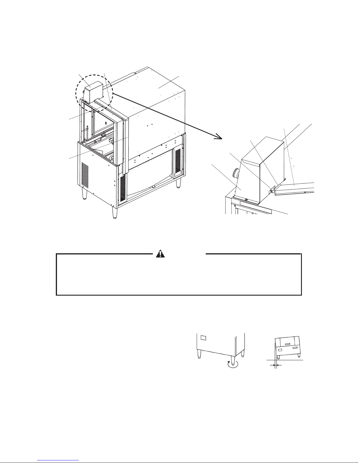
[a] SHIPPING TAPE------------------------------------------------------------------------------------ 2
[b] CHECKS BEFORE INSTALLATION----------------------------------------------------------- 3
[c] PROTECTIVE FILM-------------------------------------------------------------------------------- 3
[d] OPERATION BOX---------------------------------------------------------------------------------- 3
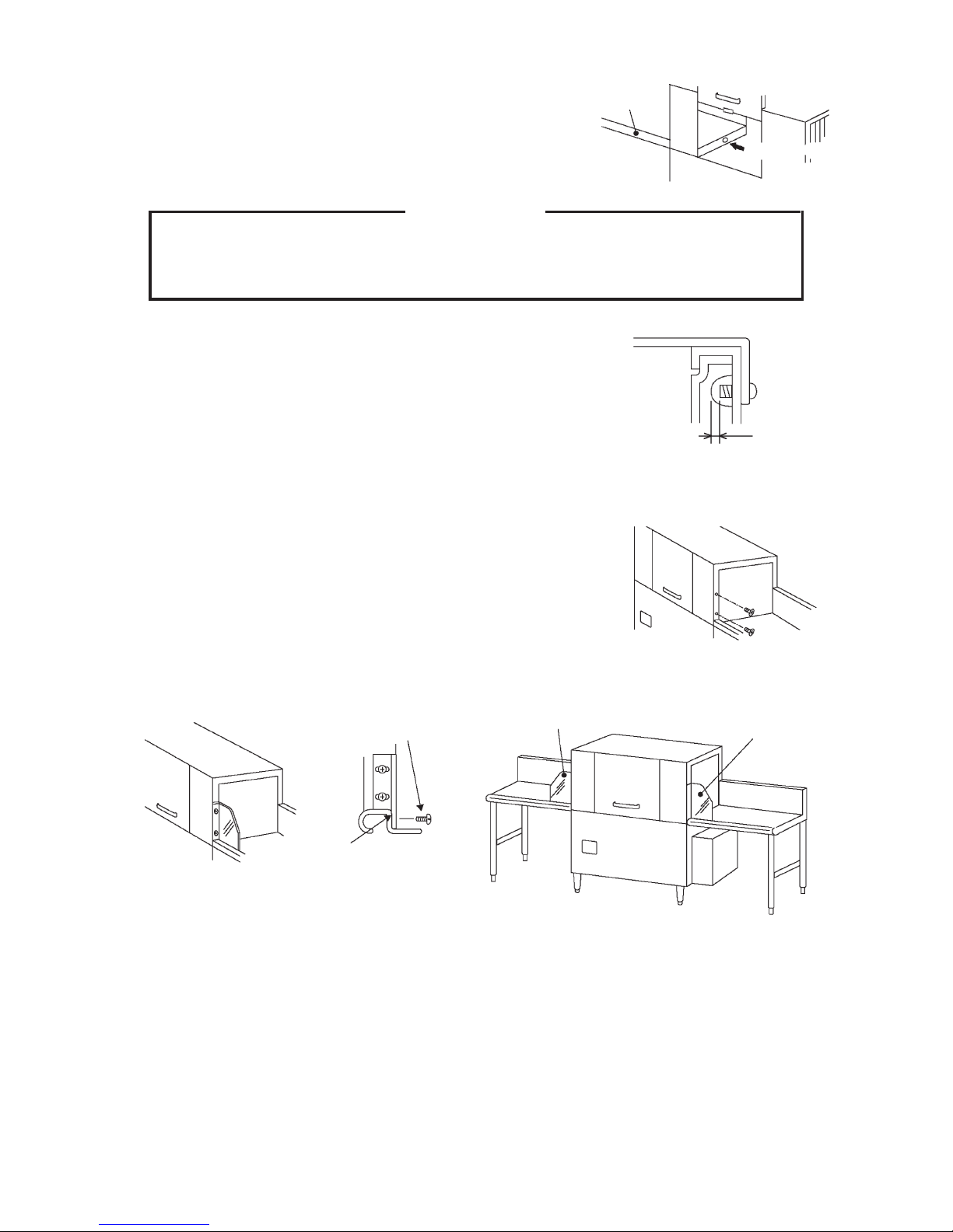
[e] CONNECTION TO A DISHTABLE ------------------------------------------------------------- 4
[f] SPLASH GUARD----------------------------------------------------------------------------------- 5
[g] TABLE LIMIT SWITCH ---------------------------------------------------------------------------- 5
3. VENTILATION ------------------------------------------------------------------------------------------- 6
4. WATER SUPPLY AND DRAIN CONNECTIONS------------------------------------------------ 7
[a] WATER HEATER CONNECTION -------------------------------------------------------------- 7
[b] PRESSURE REDUCING VALVE--------------------------------------------------------------- 7
[c] WATER SOFTENER------------------------------------------------------------------------------- 7
[d] STRAINER ------------------------------------------------------------------------------------------- 8
[e] HOT WATER SUPPLY CONNECTION ------------------------------------------------------- 9
[f] DRAIN CONNECTION (WASH TANK DRAIN) ---------------------------------------------- 9
5. ELECTRICAL CONNECTION --------------------------------------------------------------------- 10
6. PHASE REVERSAL CHECK ---------------------------------------------------------------------- 12
7. DETERGENT/RINSE AID FEEDER ------------------------------------------------------------- 13
[a] CONCENTRATION SENSOR----------------------------------------------------------------- 13
[b] DETERGENT INLET----------------------------------------------------------------------------- 13
[c] RINSE AID INLET -------------------------------------------------------------------------------- 14
[d] SIGNAL (POWER SUPPLY) CONNECTIONS-------------------------------------------- 14
8. TRIAL RUN --------------------------------------------------------------------------------------------- 15
[a] CHECKS BEFORE TRIAL RUN -------------------------------------------------------------- 15
[b] PREPARING HOT WATER SUPPLY -------------------------------------------------------- 16
[c] FINAL CHECKS----------------------------------------------------------------------------------- 16
[d] AFTER TRIAL RUN ------------------------------------------------------------------------------ 17

iii
[e] ADJUSTMENT ------------------------------------------------------------------------------------ 17
[f] LOWER WASH SPRAY ARM PRESSURE AND FLOW RATE ----------------------- 17
9. RELOCATION ----------------------------------------------------------------------------------------- 18

iv
Important Safety Information
Throughout this manual, notices appear to bring your attention to situations which could
result in death, serious injury, or damage to the unit.
WARNING Indicates a hazardous situation which could result in death or
serious injury.
CAUTION Indicates a situation which could result in damage to the unit.
IMPORTANT Indicates important information about the use and care of the
unit.
WARNING
This product should be destined only to the use for which it has been
expressly conceived. Any other use should be considered improper and
therefore dangerous. The manufacturer cannot be held responsible for injury
or damage resulting from improper, incorrect, and unreasonable use.
basic precautions including the following:
local electrical code requirements. Failure to meet these code requirements
equipment.
booster tank. See the nameplate for proper voltage and breaker/fuse sizes.
Failure to use proper breakers or fuses can result in tripped breakers, blown
fuses, or damage to existing wiring. This could lead to heat generation or
THIS UNIT MUST BE GROUNDED. Failure to properly ground this unit
could result in death or serious injury.

1
1. MOVING
WARNING
When handling the unit (unloading from
pallet, moving, installing), do not hold the
service panel or top panel, or the service
panel will open. Hold the parts indicated
by arrows only.
* Do not remove the shipping tape securing the service panel until the end of installation.
* Be careful not to damage the piping projecting from the bottom of the unit.
WARNING
1. Do not lay down the unit. The door may open and cause injury.
2. This is a heavy unit. Handle and move it with care to prevent injury.
3. When unpacking or moving the unit, be careful not to damage the parts on
the bottom.
2. INSTALLATION
WARNING
1. This product must be installed in accordance with applicable national, state,
and local regulations.
of the installation, start up the unit to check for any abnormalities, and
instruct the user on how to use and maintain the unit in accordance with the
instruction manual.
3. This unit is not intended for outdoor use. Exposure to rain may cause electric
leakage or shock.
4. To prevent fire, electric shock, injury or water leak, this unit should be
Service Panel
Top Panel

2
the risk of water leaks or injury caused by overturn or fall.
6. Avoid a site where dripping is not allowed. The unit may drip water onto the
the unit for extended periods outside of this normal temperature range may
affect performance.
8. Do not install the unit where there is a risk of freezing. If there is a possibility
that the ambient temperature may fall below 32°F (0°C) and freeze the unit,
be sure to drain the unit. The water supply line could be damaged and leak
water, resulting in damage to the surrounding property.
9. Install the unit where high temperatures and steam are allowed. During
operation, the surface temperature will reach around 176°F (80°C), and
steam will come out from between the curtains and body.
[a] SHIPPING TAPE
1) Remove the shipping tape from the exterior.
2) Remove the shipping band from the rack and package of accessories.
IMPORTANT
Do not remove the labels.
Rack
Accessories
in Carton
Upper Wash Spray Arm
Upper Rinse Spray Arm
Lower Wash Spray Arm
Lower Rinse Spray Arm
Table Limit Switch
Tank Filter
Drain Pipe Booster Tank
Emergency Stop Switch
Separator
Curtain (L)
Curtain (S)
* With accessories
installed

3
[b] CHECKS BEFORE INSTALLATION
1) Check the exterior including the front panel and service panel for damage.
3) The accessories except the rack are provided in the carton. Check that all the
and not damaged.
IMPORTANT
1. Visually inspect the exterior of the shipping container and immediately report
any damage to the carrier. Upon opening the container, any concealed
damage should also be immediately reported to the carrier.
2. The instruction manual should be handed over to the user.
[c] PROTECTIVE FILM
stainless steel exterior look unclean.
[d] OPERATION BOX
Be sure to attach the operation box before installing the unit. It is prepared at the factory to
be attached to the exit side of the top panel.
1) Remove the bolts at the exit side of the top panel. Then, attach the operation box.
2) Insert the two operation box cables from the cable cover (L) on the rear side into the
notch in the rear panel, and route them into the machine compartment. Then, remove
the four bolts from the top panel, put the cables in the accessory cable cover (S), and
use the separator inside to keep the two cables away from each other. Secure the cable
cover (S) by using the four bolts removed.
The accessory cable cover (S) should be hooked into the square hole in the back of the
operation box as shown in the illustration.
3) Remove the front panel, and pull the cables from the back of the machine compartment.
Coil and tie any extra length of cable to prevent contact with the fan blades and other
sharp edges.
4) Remove the plastic bag from the operation box connection cables coming out of the
control box, and connect the 4P and 7P connectors. Cover the cable connections with

4
[e] CONNECTION TO A DISHTABLE
WARNING
When connecting a dishtable, apply silicone sealant to a thickness of at least
in electric leakage or shock.
A dishtable facilitates loading and unloading of the rack.
Adjustable
Leg 1/2" (12.7mm)
Turn clockwise
to adjust higher
Cable Cover (S)
[accessory] Top Panel
Bolt (stainless
steel 4x8)
* Remove from
top panel
Cable Cover (L)
Cable Cover (S)
Square Hole
Hook
1) Remove the side panel where the dishtable
is to be installed.
2) Use the adjustable legs of the dishtable and
dishwasher to level them in both the left-to-
right and the front-to-rear directions. The unit
shown in the illustration.
the plastic bag, and tie it with the opening facing down.

5
IMPORTANT
To prevent possible corrosion, do not leave any shavings after drilling the hole in
the wash tank.
Min 1/2"
(12.7mm)
front frame of the dishtable.
Fit tightly
Screw if required Guard (L) Guard (R)
[g] TABLE LIMIT SWITCH
The table limit switch stops washing operation when a rack reaches the end of the clean
dishtable. It is also required to prevent damage to the dishes in the racks.
1) Drill a cable hole and mounting holes in the back frame of the clean dishtable.
Dishtable
Dishwasher
Drill a hole
3) Hook the dishtable on the wash tank. Drill a hole
in the wash tank to match the mounting hole in the
dishtable.
4) Secure the dishtable to the dishwasher with a screw.
Apply silicone sealant to the screw threads as shown on
the right and between the dishtable and the wash tank.
[f] SPLASH GUARD
Install the accessory guards (L) and (R) to prevent water
from splashing out of the entrance and exit of the wash
compartment onto the dishtable during washing operation.
1) Remove the screws from the entrance and exit of the
wash compartment.

6
3) Remove the front panel, open the slide cover on the base
to route the switch cable, then close and secure the slide
cover. Coil and tie any extra length of cable inside the
4) Remove the plastic bag from the switch connection cable coming out of the control box,
and connect the 4P connector. Cover the cable connection with the plastic bag, and tie it
with the opening facing down.
5) Secure the cable with the wire retainer on the bottom of the unit.
3. VENTILATION
WARNING
1. Installation must be in accordance with applicable national, state, and local
regulations.
2. If an exhaust hood is required to discharge steam from the dishwasher, it
should provide a minimum 200 CFM at the entrance and 400 CFM at the
exit and be a listed and labeled factory-built commercial exhaust hood tested
in accordance with UL Standard 710 by a nationally recognized testing
laboratory.
It must be installed according to the terms of its listing and the manufacturer’s
installation instructions.
(provided)
2) Put the cable of the accessory table limit switch through the cable hole in the dishtable,
and secure the switch with the bolts provided.
Three 0.24" (6mm)
Mounting Holes
0.8" (20mm)
Cable Hole
1.34"
(34mm) 4.5"
(114mm) 3.6"
(91mm)
2.93"
(74.5mm)
5.75"
(146mm)
5.9"
(150mm)
8.1" (206mm)

7
3. To use a gas water heater, thoroughly read its instruction manual. Ensure
adequate air intake and exhaust systems and exhaust hoods in accordance
with applicable national, state, and local regulations for the type and capacity
of the heater to prevent dangerous conditions due to lack of oxygen and toxic
gas generation.
4. WATER SUPPLY AND DRAIN CONNECTIONS
WARNING
Plumbing connections must comply with applicable sanitary, safety and
plumbing codes.
CAUTION
To prevent water leaks resulting in damage to the surrounding property, make
proper water supply and drain connections according to this manual.
[a] WATER HEATER CONNECTION
Make the water heater connection according to its instruction manual.
[b] PRESSURE REDUCING VALVE
Keep the water supply pressure within 10 to 70 PSIG.
If the water pressure is too high, a pressure reducing valve (not supplied) must be installed
in the water line just ahead of the dishwasher.
CAUTION
The pressure reducing valve must have a relief by-pass. Failure to use the
proper type of pressure reducing valve may result in damage to the unit.
[c] WATER SOFTENER
If water hardness exceeds 4 grains per gallon, a water softener (not supplied) must be
installed in the primary circuit (water supply inlet) of the water heater.
IMPORTANT
The recommended water hardness of not more than 4 grains per gallon is for

8
the dishwasher. If the required water hardness for the water heater is lower,
meet that requirement.
local Hoshizaki distributor for recommendations.
* Sediment, silica, chlorides or other dissolved solids may lead to a recommendation for
* If an inspection of the dishwasher or booster tank heater reveals lime build-up after the
equipment has been in service, in-line water treatment should be considered, and, if
recommended, should be installed and used as directed.
Water
Heater
Dishwasher
Water Supply Line
Shut-off Valve
Strainer (3/4" FPT)
[accessory]
Wash Tank Drain Pipe
(1-1/2" MPT)
Water
Softener
Water Supply
Valve Water
Gas
Gas Supply Line
Shut-off Valve
Drain Valve
[d] STRAINER
Attach the strainer (accessory) to the
water supply pipe on the bottom front
of the booster. To prevent water leaks,
be sure to insert the rubber gasket
(accessory) between the water supply
pipe nut and the strainer.
Pressure
Reducing Valve
Booster
Tank
Booster Tank Drain
Pipe (1" MPT)
* Attach the accessory strainer to the booster tank water supply inlet.
Water Hammer Arrestor
Gasket (accessory)
Strainer (accessory)
FPT
Bottom
Water Supply Pipe
LoosenTighten

9
[e] HOT WATER SUPPLY CONNECTION
WARNING
To reduce the risk of burns, the hot water supply line must be thermally
* Where there is a risk of water hammer, it is recommended to install a water hammer
arrestor between the dishwasher and water heater.
* Required incoming water temperature:
Incoming Water Temperature
Minimum Recommended Maximum
110°F (43°C) 140°F (60°C) 167°F (75°C)
Wash Temperature Rinse Temperature
Minimum Recommended Minimum Recommended
160°F (71°C) 160°F (71°C) 180°F (82°C) 180°F (82°C)
Where there is a risk of freezing, install a drain valve (shut-off valve) between the water
supply valve and dishwasher.
IMPORTANT
When an instantaneous water heater is used, it must be an exclusive type for a
dishwasher and provided with an end stop system.
[f] DRAIN CONNECTION (WASH TANK DRAIN)
CAUTION
To ensure proper draining, do not route the drain pipe where it can be stepped
on.
Drain Pipe (pitched)
Min 2"
(5cm)
Floor Drain
drain. An air gap of a minimum of 2 vertical inches (5 cm)
should be between the end of the drain pipe from the
* If a grease trap is required in the drain line by regulations,
check that it is present at the time of installation.

10
5. ELECTRICAL CONNECTION
WARNING
1. Electrical connection must be hard-wired and must meet national, state, and
local electrical code requirements. Failure to meet these code requirements
to equipment. A ground fault circuit interrupter (GFCI) must be installed to
meet these code requirements.
2. This unit requires independent power supplies for the dishwasher and for the
booster tank. See the nameplate for proper voltage and breaker/fuse sizes.
Failure to use proper breakers or fuses can result in tripped breakers, blown
3. THIS UNIT MUST BE GROUNDED. Failure to properly ground this unit could
result in death or serious injury.
4. Make sure the power supply is off before making any electrical connections
to prevent possible electric shock. Lockout/Tagout to prevent the power from
being turned back on inadvertently.
Hook - Drain
Band
(not provided)
Bolt (M6 x 12)
Drain Pipe
* Keep parallel to the unit
* Installable at either side
* If the drain pipe running from side to side at the bottom is long and coming out from
under the unit, the drain pipe weight may cause deformation of the wash tank bottom.
In such case, insert the accessory hook - drain into the square hole in the bottom of the
unit, secure with the bolt provided, and use a band to hold the drain pipe.

11
AC Supply Voltage Maximum Breaker/Fuse Size Minimum Circuit Ampacity
208 - 230V / 60Hz / 3Ph Dishwasher 70A
Booster Tank 80A
Dishwasher 70A
Booster Tank 80A
* Usually an electrical permit and services of a licensed electrician are required.
* The maximum allowable voltage variation is ±10 percent of the nameplate rating.
Control Box Cover
Control Box
Voltage Tap
Switch
Terminal Block
1) Remove the front panel.
2) Remove the control box cover.
3) Connect the two ground wires to the two ground screws in the base.
the unit, and then through the two top bushings on the right side of the control box.
Use the cable ties provided to bind the wires from inside the control box to prevent
disconnection.
WARNING
The power supply wires must slope downward from the conduits to prevent
entrance of water through the bushing into the control box.
IMPORTANT
box. The extra length allows the control box to be pulled out for service after
installation.
* The voltage tap switch on the right side of
the control box must be positioned to match
incoming voltage at startup (factory default:
230V).
* The opening for the power supply connection
* This dishwasher requires independent
power supplies for the dishwasher and for
the booster tank. Route the power supply
wires from the bottom of the dishwasher to
the two terminal blocks inside the control
box as follows:
230V
208V

12
Terminal Block for
Dishwasher (left)
Terminal Block for
Booster Tank (right)
Bushing
1-1/4" Conduit
Grounding
6. PHASE REVERSAL CHECK
The unit is provided with a phase reversal relay to prevent operation in case of phase
reversal. To check for phase reversal, follow the steps below.
1) Make sure all wiring connections have been properly made. For details, see “5.
3) If the display is blank, turn off the power supply. Lockout/Tagout to prevent the power
from being turned back on inadvertently.
4) Swap 2 of the power supply wires on the dishwasher terminal block.
display lights up.
6) Turn off the power supply.
Downgrade
5) Connect the terminals to the terminal blocks. Check the wire colors against the wiring
label attached inside the front panel to prevent miswiring. The terminal block on the left
is for the dishwasher, and the one on the right is for the booster tank.
6) Reattach the control box cover and the front panel.
Line Side Screw Torque:
6 AWG - 45 in lbs
8 AWG - 40 in lbs

13
7. DETERGENT/RINSE AID FEEDER
WARNING
1. Electrical connection must be hard-wired and must meet national, state, and
local electrical code requirements. Failure to meet these code requirements
to equipment.
2. THIS UNIT MUST BE GROUNDED. Failure to properly ground this unit could
result in death or serious injury.
This dishwasher must be operated with an automatic detergent feeder and an automatic
rinse aid feeder, including a visual means to verify that detergents/rinse aids are delivered
or to signal if detergents/rinse aids are not available for delivery.
Any feeders provided by a detergent supplier must be installed as described below. For
electrical and plumbing connections, follow the instructions in this manual and the manual
supplied with the feeder. Consult with the detergent supplier or an authorized Hoshizaki
service company for further details.
The dishwasher uses 0.48 gallons of rinse water per cycle. This information is used when
setting a detergent/rinse aid pump.
[a] CONCENTRATION SENSOR
Remove the front panel. Locate the mounting hole in the front center of the tank bottom.
Cap
22mm
Hole
[b] DETERGENT INLET
1) Connect the detergent inlet to the mounting hole in the entrance side of the wash
compartment.
2) Remove the cover attached inside the side panel.
3) Remove the cap and nut from the side of the tank. Install the detergent inlet to the
uncapped hole.

14
cannot be installed to the side of the tank, drill a mounting hole in the entrance of
the wash compartment or the back of the top panel.
Mounting Hole
Side Panel
Left Side
(JWE-2400CUA-L)
Within This Area
Rinse Spray Arm
[c] RINSE AID INLET
Remove the front panel. Locate the rinse aid inlet at the end of the hose reaching from the
back of the rinse pump to the front of the unit.
JWE-2400CUA-L: back right
JWE-2400CUA-R: back left
Plug
* The vent fan control signal is emitted during the wash and rinse cycles (while the wash
pump or rinse pump is running).
Terminal Block
[d] SIGNAL (POWER SUPPLY) CONNECTIONS
1) Remove the front panel, open the slide cover on the base to
route the detergent and rinse aid feeder cables and the vent fan
control signal cable.
2) Connect the feeder cables to the terminal block on the side of
the control box. Connect the vent fan control signal cable (2A or
less) to the terminal block on the front of the wash pump motor
bracket. For details, see the wiring diagram below.
Clamped to Frame Hose

15
IMPORTANT
1. Be sure to use detergent and rinse aid feeders with protective fuses.
2. Ensure the power supply capacity of 208 to 230V AC, 1A or less, and use
insulated terminals to connect the feeders to the terminal block.
the rinse pump runs. The rinse aid feeder operates only in a normal rinse
cycle when the rinse pump and the conveyor run at the same time.
8. TRIAL RUN
WARNING
To reduce the risk of electric shock, do not touch the electrical parts with damp
hands.
[a] CHECKS BEFORE TRIAL RUN
2) Check that the upper and lower wash/rinse spray arms are in place. The upper wash
spray arm provided in the carton should be installed properly.
3) Check that the curtains provided in the carton are properly installed at the entrance,
center, and exit of the wash compartment. The curtains (S) should be located at the
entrance and exit with their patterned side out.
4) Close the service panel.
Other manuals for JWE-2400CUA-L-25B
2
This manual suits for next models
1
Table of contents
Other Hoshizaki Dishwasher manuals

Hoshizaki
Hoshizaki HW-600B3 RT User manual

Hoshizaki
Hoshizaki JWE-620UA-6B User manual

Hoshizaki
Hoshizaki HW-600A User manual

Hoshizaki
Hoshizaki JWE-620UA-6B User manual

Hoshizaki
Hoshizaki JWE-2400CUA-L-25B User manual

Hoshizaki
Hoshizaki HW 600B User manual

Hoshizaki
Hoshizaki JWE-2400CUA-L-25B User manual

Hoshizaki
Hoshizaki JWE-620UA-6B User manual

Hoshizaki
Hoshizaki JWE-620UA-6B User manual