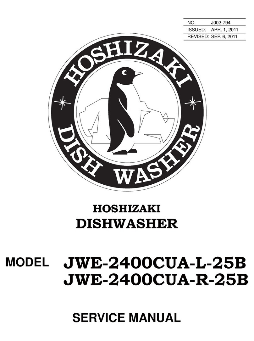
Hoshizaki JWE-2400CUA-L-25B User manual

JWE-2400CUA-L-25B
JWE-2400CUA-R-25B
DISHWASHER
INSTRUCTION MANUAL
FOR END USER L1J002111 (041811)

i
IMPORTANT
Only qualified service technicians should install, service and maintain the
product. No installation, service or maintenance should be undertaken until
the technician has thoroughly read this Instruction Manual. Likewise, the
owner/manager should not proceed to operate the product until the installer
has instructed them on its proper operation. Failure to install, operate, and
maintain the equipment in accordance with this manual may adversely affect
safety, performance, component life, and warranty coverage.
Hoshizaki provides this manual primarily to assist qualified service technicians in the
installation, maintenance, and service of the product.
Should the reader have any questions or concerns which have not been satisfactorily
addressed, please call, write, or send an e-mail message to the Hoshizaki Technical
Support Department for assistance.
HOSHIZAKI AMERICA, INC.
618 Highway 74 South
Peachtree City, GA 30269
Attn: Hoshizaki Technical Support Department
Phone: 1-800-233-1940 Technical Support
(770) 487-2331
Fax: 1-800-843-1056
(770) 487-3360
E-mail: [email protected]
Web Site: www.hoshizaki.com
NOTE: To expedite assistance, all correspondence/communication MUST include the
following information:
* Model Number
* Serial Number
* Complete and detailed explanation of the problem.

ii
IMPORTANT
This manual should be read carefully before the product is installed and
operated. Only qualified service technicians should install, service, and
maintain the product. Read the warnings contained in this booklet carefully as
they give important information regarding safety. Please retain this booklet for
any further reference that may be necessary.
CONTENTS PAGE
1. CONSTRUCTION --------------------------------------------------------------------------------------1
[a] GENERAL--------------------------------------------------------------------------------------------1
[b] OPERATION PANEL-------------------------------------------------------------------------------3
[c] CONVEYOR SPEED SWITCH------------------------------------------------------------------4
[d] ACCESSORIES-------------------------------------------------------------------------------------4
[e] PERIODICAL REPLACEMENT PARTS ------------------------------------------------------5
2. CHECKS BEFORE OPERATION-------------------------------------------------------------------5
[a] CHECKS AFTER INSTALLATION--------------------------------------------------------------5
[b] WATER REQUIREMENTS-----------------------------------------------------------------------5
[c] CHECKS BEFORE OPERATION---------------------------------------------------------------6
3. CHECKING THE DETERGENT TANK AND RINSE AID TANK-----------------------------7
4. CHECKING THE OPERATION BOX---------------------------------------------------------------7
5. CHECKING THE TABLE LIMIT SWITCH---------------------------------------------------------7
6. PREPARING THE WASH COMPARTMENT-----------------------------------------------------7
[a] AUTO FILL -------------------------------------------------------------------------------------------8
7. LOADING -------------------------------------------------------------------------------------------------9
[a] PREWASH -------------------------------------------------------------------------------------------9
[b] LOADING DISHES---------------------------------------------------------------------------------9
[c] LOADING RACKS-------------------------------------------------------------------------------- 10
8. WASH AND RINSE----------------------------------------------------------------------------------- 10
[a] OPERATING TEMPERATURES-------------------------------------------------------------- 10
[b] RACK CONVEYOR SPEED AND WASH INITIATION---------------------------------- 10
9. UNLOADING--------------------------------------------------------------------------------------------11
10. INSUFFICIENT WASHING RESULTS ---------------------------------------------------------- 12
11. SHUTDOWN------------------------------------------------------------------------------------------- 13
iii
12. INTERRUPTION-------------------------------------------------------------------------------------- 14
13. EMERGENCY STOP -------------------------------------------------------------------------------- 14
14. DAILY MAINTENANCE ----------------------------------------------------------------------------- 15
15. WEEKLY MAINTENANCE-------------------------------------------------------------------------- 20
[a] HEATER -------------------------------------------------------------------------------------------- 20
[b] EXTERIOR----------------------------------------------------------------------------------------- 20
16. MONTHLY INSPECTION--------------------------------------------------------------------------- 20
[a] WATER SUPPLY LINE-------------------------------------------------------------------------- 20
17. TROUBLESHOOTING ------------------------------------------------------------------------------ 21
[a] TROUBLES REQUIRING IMMEDIATE SERVICE CALL-------------------------------- 21
[b] TROUBLES REQUIRING CHECK BY USER---------------------------------------------- 21
[c] TROUBLES WITHOUT ERROR CODE INDICATION----------------------------------- 22
18. LONG STORAGE, RELOCATION, DISPOSAL, TRANSFER----------------------------- 22

iv
Important Safety Information
Throughout this manual, notices appear to bring your attention to situations which could
result in death, serious injury, or damage to the unit.
WARNING Indicates a hazardous situation which could result in death or
serious injury.
CAUTION Indicates a situation which could result in damage to the unit.
IMPORTANT Indicates important information about the use and care of the
unit.
WARNING
This product should be destined only to the use for which it has been
expressly conceived. Any other use should be considered improper and
therefore dangerous. The manufacturer cannot be held responsible for injury
or damage resulting from improper, incorrect, and unreasonable use.
To reduce the risk of death, electric shock, serious injury, or fire, follow
basic precautions including the following:
• Electrical connection must be hard-wired and must meet national, state, and
local electrical code requirements. Failure to meet these code requirements
could result in death, electric shock, serious injury, fire, or severe damage to
equipment.
• This unit requires independent power supplies for the dishwasher and for the
booster tank. See the nameplate for proper voltage and breaker/fuse sizes.
Failure to use proper breakers or fuses can result in tripped breakers, blown
fuses, or damage to existing wiring. This could lead to heat generation or
fire.
• THIS UNIT MUST BE GROUNDED. Failure to properly ground this unit
could result in death or serious injury.
• This unit should be disassembled or repaired only by qualified service
personnel to reduce the risk of electric shock, injury, or fire.
• Do not make any alterations to the unit. Alterations could result in electric
shock, injury, fire, or damage to the unit.

1
[17] [16]
[1] [15]
[14]
[13]
[2]
[12]
[3]
[4] [11]
[10]
[5]
[9]
[6] [7] [8]
1. CONSTRUCTION
[a] GENERAL
* The illustration shows the “-L” model (rack flows from left to right).
[1] Upper Wash Spray Arm, Lower Wash Spray Arm
Sprays wash water onto dishes.
[2] Rack Rail, Conveyor
[3] Drain Pipe
Pull out to drain.
[4] Heater
Keeps wash water at proper temperature.

2
[5] Conveyor Speed Switch
See “[c] CONVEYOR SPEED SWITCH”.
[6] Pump Filter
Prevents scraps from being drawn into the pump.
[7] Separator
[8] Water Level Sensor
Detects wash water level.
[9] Booster Tank
[10] Tank Filter
Separates wash water and scraps.
[11] Table Limit Switch
Stops washing operation when a rack reaches the end of the clean dishtable.
[12] Upper Rinse Spray Arm, Lower Rinse Spray Arm
Sprays rinse water onto dishes to rinse off detergent.
[13] Curtain
Prevents splashing from the entrance and exit of the wash compartment.
[14] Emergency Stop Button
Stops the unit in case of emergency.
[15] Operation Panel
See “[b] OPERATION PANEL”.
[16] Hook
Holds the service panel in its open position.
[17] Service Panel

3
[1]
[2]
[3]
[4]
[5]
[6]
[7]
[8]
[b] OPERATION PANEL
[1] Water Temperature Lamps
Light up to indicate the water temperature shown in the display.
[2] “AUTO FILL” Lamp
Flashes during the auto fill cycle, and goes off at the end of the cycle.
[3] “READY” Lamp
Lights up when the auto fill cycle completes and the dishwasher is ready to wash.
[4] “WASH” Lamp
Lights up during washing operation.
[5] Up Button, Down Button
Indicates the total hours of operation in six digits by two digits each time.
Example: 123,456 hours are indicated by
Press to stop the beep in case of error.
Service personnel also use these buttons to change the controller settings.

4
[1]
[6] Display
Indicates wash water temperature in wash cycle, rinse water temperature in rinse
cycle, and error codes in case of trouble. See “17. TROUBLESHOOTING”.
[7] “CHANGE” Button
Press to change the wash tank water temperature shown in the display to the booster
tank water temperature.
[8] “ON/OFF” Button
Turns on/off the power for operation.
[c] CONVEYOR SPEED SWITCH
[1] Conveyor Speed Switch
Changes the rack conveyor speed in three levels (high, medium, low).
[d] ACCESSORIES
Instruction manual x 1 Installation manual x 1
Universal rack x 1 Operation sheet x 1
Required for installation:
Operation box assembly x 1 Hook - drain x 1
Guard (L), (R) x 1 each Cable cover (S) x 1
Hook - drain securing bolt w/washer
(stainless steel M6 x 12) x 1 Upper wash spray arm x 1
Cable tie x 2
Curtain (S) x 2 Curtain (L) x 1
Shaft - curtain x 3 (2 types) Table limit switch x 1
Strainer x 1 Gasket x 1

5
[e] PERIODICAL REPLACEMENT PARTS
Part Name Replacement Frequency
Curtain (S) [entrance/exit]
Part number: 2X0532G01
Curtain (L) [center]
Part number: 2X0533G01
2 years
Life cycle depends on frequency of use, detergent,
and temperature conditions. Check the curtains
once a month for deterioration (e.g. deformation,
hardening).
O-ring [upper/lower wash spray arm]
Part number: 7611-P045 2 years
Life cycle depends on frequency of use, detergent,
and temperature conditions. Check the o-rings
every day for deterioration (e.g. deformation,
hardening) and dislocation.
2. CHECKS BEFORE OPERATION
WARNING
1. To prevent possible water leak, electric shock or fire, the installation must be
carried out by qualified personnel.
2. When using a gas water heater, thoroughly read its instruction manual.
Ensure adequate air intake and exhaust systems and exhaust hoods in
accordance with applicable laws for the type and capacity of the heater to
prevent dangerous conditions due to lack of oxygen and toxic gas generation.
[a] CHECKS AFTER INSTALLATION
* In the presence of the installer, check for proper installation according to the installation
manual provided.
* Receive the installation manual from the installer, and keep it for later reference.
[b] WATER REQUIREMENTS
* Proper water quality can improve warewashing performance by reducing spotting,
lowering chemical supply costs, improving productivity and extending equipment life.
Local water conditions vary. The recommended proper water treatment for effective and
efficient use of this equipment will also vary depending on the local water conditions. Ask
your municipal water supplier for details about local water specifics prior to installation.
* Recommended water hardness is not more than 4 grains of hardness per gallon.
Chlorides must not exceed 50 parts per million. Water hardness above 4 grains per gallon

6
should be treated by a water softener or in-line treatment. Water treatment has been
shown to reduce costs associated with machine cleaning, reduce the need for deliming
the dishwasher, reduce detergent usage and reduce corrosion of metallic surfaces in the
booster tank and dishwasher.
* Sediment, silica, chlorides or other dissolved solids may lead to a recommendation for
particulate filtration or reverse osmosis treatment.
* If an inspection of the dishwasher or booster tank reveals lime build-up after the
equipment has been in service, in-line water treatment should be considered, and,
if recommended, should be installed and used as directed. Contact an authorized
Hoshizaki service company for specific recommendations.
[c] CHECKS BEFORE OPERATION
* Ambient temperature should be within 41 to 95°F (5 to 35°C). Operation of the unit for
extended periods outside of this normal temperature range may affect performance.
WARNING
To avoid the risk of corrosion, clogging and health problems, be sure to use
potable water.
* To prevent water leaks resulting in damage to the surrounding property, keep the water
supply pressure within 10 to 70 PSIG. If the water pressure is too high, a pressure
reducing valve (option) must be installed according to the water heater’s instruction
manual.
* The power supply voltage and capacity must be as follows:
Power supply voltage: 208 - 230V / 60Hz / 3Ph
Operating limits: 187 - 253V
Maximum breaker/fuse size: dishwasher 70A, booster tank 80A
Minimum circuit ampacity: dishwasher 70A, booster tank 80A
* The wash compartment has been cleaned before shipping. But clean it again before
starting up the unit, and check for proper installation of each part. See “14. DAILY
MAINTENANCE”.
* Check the electrical, water, and drain connections before starting up the unit. See “16.
MONTHLY INSPECTION”.
* Always use a dishwasher detergent instead of a neutral detergent for kitchen use.
(Some dishwasher detergents are not suitable. Contact an authorized Hoshizaki service
company for further details.)

7
3. CHECKING THE DETERGENT TANK AND RINSE AID TANK
Follow the instructions of the detergent and rinse aid suppliers to check the detergent tank
and rinse aid tank safely.
IMPORTANT
Be sure to read the warning and caution labels attached to the detergent tank
and rinse aid tank.
4. CHECKING THE OPERATION BOX
Check that the accessory operation box assembly containing the operation panel and
emergency stop button is installed in its correct position.
5. CHECKING THE TABLE LIMIT SWITCH
Check that the accessory table limit switch is installed in its correct position to stop
washing operation when a rack reaches the end of the clean dishtable.
6. PREPARING THE WASH COMPARTMENT
Check that the wash compartment has been cleaned with all the parts in place. If not,
clean the wash compartment according to “14. DAILY MAINTENANCE”, and install the
parts following the instructions below.
Upper Wash Spray Arm Upper Rinse Spray Arm
Lower Wash Spray Arm
Lower Rinse Spray Arm
Table Limit Switch
Tank FilterDrain Pipe Booster Tank
Emergency Stop Switch
Separator
Curtain (L)
Curtain (S)

8
4) Check that the curtains are installed at the entrance, center, and exit of the wash
compartment.
5) Open the gas and water supplies.
IMPORTANT
To operate the water heater, follow its instruction manual.
6) Turn on the water heater.
7) Press the “ON/OFF” button. The display lights up. If the wash tank is full, the “READY”
lamp lights up. If the wash tank is not full, the “AUTO FILL” lamp flashes and the auto fill
cycle starts.
[a] AUTO FILL
The auto fill cycle refers to automatic operation of the unit to fill the wash tank with enough
hot water for washing. The cycle takes around 15 minutes (12 minutes for other than initial
auto fill cycle). Then, the dishwasher is ready for washing.
1) Close the service panel. The “AUTO FILL” lamp flashes, and the auto fill cycle starts.
The booster tank heats up water in the first 5 minutes of the cycle, then the rinse spray
arms supply hot water to the wash tank.
IMPORTANT
Do not open the service panel while the “AUTO FILL” lamp is flashing.
Otherwise, the rinse pump stops and the auto fill cycle ends without filling the
wash tank.
2) After the auto fill cycle completes, the unit stops, the “READY” lamp lights up (“AUTO
FILL” lamp goes off), and the buzzer sounds.
1) Check that the separator, tank filters and drain pipe are
in place.
2) Check that the upper and lower wash spray arms are in
place.
3) Check that the upper and lower rinse spray arms are in
place.

9
Water Heater
Gas Supply Line
Shut-off Valve
Water Supply Line
Shut-off Valve
Booster Tank Water Supply Valve
Drain Valve
Dishwasher
IMPORTANT
If the dishwasher has been drained
out to prevent freezing, close the
drain valve before opening the water
supply line shut-off valve. With the
drain valve left open, hot water will
be wasted.
7. LOADING
[a] PREWASH
1) Remove any leftovers (ex. meat, fish, vegetables), chopsticks, toothpicks, straws, paper
products and plastics from the dishes. Never use steel wool on ware to be loaded into
the dishwasher.
CAUTION
Do not put scraps in the dishwasher, as this may cause reduction in wash
performance or failure.
2) To remove heavy soils such as baked gratin and steamed egg or rice, soak the dishes in
hot water before loading them in the dishwasher.
IMPORTANT
1. Do not allow a large amount of neutral detergent in the dishwasher.
2. Use a suitable rack for dishes.
[b] LOADING DISHES
1) Place the rack on the dishtable.
2) Keep the dishes within the rack, otherwise they
may be damaged.
3) Do not stack the dishes, otherwise they cannot be
washed properly.
Correct Incorrect
Stacked Sticking out
Facing up

10
4) Load glasses upside down into the glassware
rack, otherwise they cannot be washed properly
and rinsed thoroughly or they may touch each
other and be damaged.
Dishes or cups with a deep bottom rim cannot be
rinsed thoroughly with wash water left inside the
rim. Load them as shown below.
If the above loading is not practical, the rinse cycle
time must be extended. Contact an authorized
Hoshizaki service company for further details.
5) The opening is about 20” (520 mm) high. Keep the loaded rack lower than this height.
Do not force large items into the dishwasher, otherwise they may be damaged or block
the spray arms.
[c] LOADING RACKS
For optimum washing results, load racks as illustrated.
Dishes Trays
Correct Incorrect
Correct Incorrect
Water remains
Water remains
8. WASH AND RINSE
[a] OPERATING TEMPERATURES
Operating temperatures are as follows:
Wash Temperature Rinse Temperature
Minimum Recommended Minimum Recommended
160°F (71°C) 160°F (71°C) 180°F (82°C) 180°F (82°C)
[b] RACK CONVEYOR SPEED AND WASH INITIATION
The rack conveyor speed is adjustable by the conveyor speed switch on the front panel.

11
High: Light soils
Medium: Normal soils
Low: Heavy soils
1) Set the conveyor speed switch to the desired speed.
2) Close the service panel. The dishwasher will not start with the service panel open.
3) Check that the “READY” lamp on the operation panel is on.
4) Push the rack into the entrance of the wash compartment. After the wash spray arms
start spraying water, the conveyor moves the rack into position. If the rack does not
move, push the rack further into the dishwasher.
WARNING
Never put your hands or look into the wash compartment while the unit is
running. Always press the “ON/OFF” button to turn off the unit before checking
the inside.
IMPORTANT
If the operation is resumed with a rack left inside, the unit may not start washing
or rinsing. In this case, push the next rack into the entrance of the wash
compartment to trip the start switch located inside.
9. UNLOADING
WARNING
1. To prevent possible burns, handle the rack, dishes, and interior parts [around
176°F (80°C)] with care after washing.
2. To prevent the risk of burns, do not touch the hot water [140 to 176°F (60 to
80°C)] inside the wash tank directly.
3. To prevent possible burns or injuries, do not put your hands into the entrance
or exit of the wash compartment while the unit is running.
1) The conveyor automatically pushes the rack out of the exit. Slide the rack onto the
dishtable.

12
2) When washing racks consecutively, remove the clean
racks before they fill up the dishtable. Otherwise, the
table limit switch trips to stop operation when a rack
reaches the end of the clean dishtable. Then, “L1”
appears in the display and the buzzer sounds three
times.
3) To resume operation, remove the clean racks. If a rack is
left inside the wash compartment, push in the next rack.
IMPORTANT
1. When carrying a loaded rack, use both hands to keep it level.
2. To prevent damage, keep glassware away from each other while they are still
hot [more than 104°F (40°C)].
10. INSUFFICIENT WASHING RESULTS
If washing results seem insufficient, check for the following possible causes:
* The dishes are packed and stacked in the rack. Reload the dishes. See “7. [b] LOADING
DISHES”.
* The tank filters or pump filter is clogged. Clean them. See “14. DAILY MAINTENANCE”.
* The spray arm nozzles are clogged. Clean them. See “14. DAILY MAINTENANCE”.
* The detergent tank is out of detergent. Replace it with a new tank.
* The wash water temperature is too low. Check and raise the temperature of water
supplied by the booster tank [recommended 140°F (60°C)].
* Wash water is not clean. Press the “ON/OFF” button, check that the display goes off, and
pull out the drain pipe to drain the wash water. Reinsert the drain pipe, close the service
panel, then press the “ON/OFF” button to supply fresh wash water.
* The dishes are heavily soiled. Preclean before loading the dishes.
* Iron or tannin content in wash water turns the dishes yellowish or faintly black. Soak the
dishes in a plastic bucket containing hot water and commercial bleach.
* White spots left on clear glassware can be caused by different reasons. Consult with an
authorized Hoshizaki service company or the detergent supplier.
Table Limit Switch

13
11. SHUTDOWN
CAUTION
If there is a possibility that the
ambient temperature may fall below
32°F (0°C) and freeze the unit, be
sure to drain the unit. The water
supply line could be damaged and
leak water, resulting in damage to
the surrounding property.
To drain out the water heater, close
the water supply line shut-off valve,
and open the drain valve and water
supply valve.
1) Press the “ON/OFF” button on the operation panel. The display and lamps go off.
2) Turn off the water heater.
3) Turn off the gas and water supplies.
IMPORTANT
To operate the water heater, follow its instruction manual.
4) Open the service panel.
IMPORTANT
Be sure to hook the service panel in its open position.
5) Pull out the drain pipe to drain water from the
wash tank.
Water Heater
Gas Supply Line
Shut-off Valve
Water Supply Line
Shut-off Valve
Booster Tank Water Supply Valve
Drain Valve
Dishwasher
Service Panel
Hook

14
WARNING
When pulling out the drain pipe, be careful not to touch the wash water. It may
cause burns or skin irritation. Turn the drain pipe if it is hard to pull out.
6) Remove the two tank filters without spilling
scraps inside.
12. INTERRUPTION
WARNING
To prevent hot water from splashing and causing burns, do not open the service
panel while the unit is running. Press the “ON/OFF” button and wait until the unit
stops.
1) To interrupt washing operation, press the “ON/OFF” button on the operation panel. The
display and lamps go off, and the unit stops.
2) To resume operation, press the “ON/OFF” button. The display and lamps light up.
WARNING
If the operation is resumed with a rack left inside, the unit may suddenly start
washing or rinsing. Never put your hands or look into the wash compartment
while the unit is running.
IMPORTANT
1. Before resuming operation, be sure to close the service panel.
2. If the operation is resumed with a rack left inside, the unit may not
start washing or rinsing. In this case, push the next rack into the wash
compartment to trip the start switch located inside.
13. EMERGENCY STOP
1) To make an emergency stop, press the emergency stop button (red) located on top of
the unit. The display and lamps go off, and the unit stops.
2) To resume operation, turn the emergency stop button clockwise to unlock.

15
3) Press the “ON/OFF” button on the operation panel. The display and lamps light up.
14. DAILY MAINTENANCE
IMPORTANT
Be sure to clean the dishwasher after closing time every day. It is difficult to
remove heavy soils left overnight. In high temperature conditions, food scraps
will rot and affect sanitary operation.
1) Remove the three curtains at the entrance, center, and
exit of the wash compartment.
2) Open the service panel.
3) To remove the upper wash spray arm, hold it securely
with one hand, then pull the front lever towards you
with the other hand.
4) To remove the lower wash spray arm, hold both sides,
slightly lift the front off the pins, pull the arm towards
you, then lift off the back.
5) To remove the upper rinse spray arm, turn the top
away from you to unhook, then lift off the end of the
pipe.
Other manuals for JWE-2400CUA-L-25B
2
This manual suits for next models
1
Table of contents
Other Hoshizaki Dishwasher manuals

Hoshizaki
Hoshizaki JWE-2400CUA-L-25B User manual

Hoshizaki
Hoshizaki JWE-620UA-6B User manual

Hoshizaki
Hoshizaki HW-600A User manual

Hoshizaki
Hoshizaki JWE-620UA-6B User manual

Hoshizaki
Hoshizaki HW 600B User manual

Hoshizaki
Hoshizaki JWE-620UA-6B User manual

Hoshizaki
Hoshizaki JWE-2400CUA-L-25B User manual

Hoshizaki
Hoshizaki JWE-620UA-6B User manual

Hoshizaki
Hoshizaki HW-600B3 RT User manual