Hoteam Orion Series User manual

Orion Series Low Frequency UPS
Orion-ONL-10K/33-DC384, Orion-ONL-15K/33-DC384
Orion-ONL-20K/33-DC384, Orion-ONL-30K/33-DC384
Orion-ONL-40K/33-DC384, Orion-ONL-60K/33-DC384
Orion-ONL-80K/33-DC384, Orion-ONL-100K/33-DC384
Orion-ONL-120K/33-DC384, Orion-ONL-160K/33-DC384
Orion-ONL-200K/33-DC384
Quick Guide
Shandong Hoteam Technology Group CO. , LTD

Content
1. Introduction.................................................................................................... 1
1.1 Overview.......................................................................................................1
1.2 Basic structure...............................................................................................1
1.3 Working mode ...............................................................................................1
1.4 Overview.......................................................................................................5
2. Important Safety Warning ............................................................................. 6
2.1 Conventions and used symbols........................................................................6
2.2 Safety instructions .........................................................................................7
3. Installation.................................................................................................... 10
3.1 Basic requirement ........................................................................................ 10
3.2 Disassembling and moving............................................................................ 11
4. Electrical connection..................................................................................... 13
4.1 Power connection ........................................................................................ 13
4.2 Communication............................................................................................ 17
5. Commissioning.............................................................................................. 21
5.1 Start up procedure....................................................................................... 21
5.2 Shutdown procedure .................................................................................... 22
5.3 Maintenance bypass operation ...................................................................... 22
6. Interface ....................................................................................................... 23
6.1 Control panel............................................................................................... 23
6.2 LCD information........................................................................................... 23
6.3 Sub-menus.................................................................................................. 25
7. Maintenance.................................................................................................. 50
7.1 System maintenance .................................................................................... 50
7.2 Battery maintenance .................................................................................... 50
8. Trouble shooting ........................................................................................... 51
8.1 Warning code .............................................................................................. 51
8.2 Fault code ................................................................................................... 52
9. Specification.................................................................................................. 53
10. Parallel Installation Guide.......................................................................... 56
10.1 Introduction .............................................................................................. 56
10.2 Parallel Kit Overview................................................................................... 56
10.3 Setting and LCD display .............................................................................. 60
10.4 Specification .............................................................................................. 60
10.5 Trouble shooting ........................................................................................ 61
1
1. Introduction
1.1 Overview
This UPS series is a double conversion system with sinewave output. It supplies
continuous, stable, clean power for commercial and industrial environments. When the
utility is lost accidentally, the UPS system will use the power from battery to output
without interruption.
This system is applied an advanced digital controller to control the double conversion
system, and with an isolated transformer at the output to protect the load and the UPS
itself. The UPS is also built-in user-friendly LCD interface and multiple communications
including Modbus, RS-232 and intelligent slot. With free download software, this UPS
provides complete power solution of monitoring and controlling remotely.
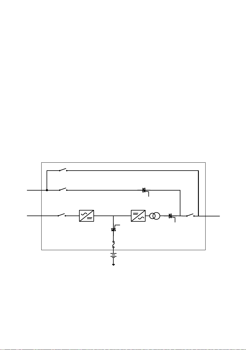
1.2 Basic structure
The whole system consists of REC module, INV module, static bypass, maintain bypass
and battery controller. The output of the UPS are switched over to either line input or
bypass input with two SCRs operated in parallel. The basic structure is shown as below:
SCR3
SCR2
Bypass
input
Line input
Fuse
Load
output
ISO TX
SCR1
REC Module INV Module
Battery
SW3
SW2
SW4
SW1
1.3 Working mode
This part will introduce the working mode of the UPS system.
1.3.1 Line mode
When the UPS is working in line mode, the AC input will be rectified by REC module, and
then be converted to the output via INV module. Meanwhile, the battery is being
charged. At this time, static bypass is in standby.
SW3
SW1

2
REC module INV module
Battery
Line input
Bypass input
1.3.2 Battery mode
When the utility fails, the UPS will transfer to battery mode without interruption. The
UPS converts the power from battery to output. At this time, static bypass is still in
standby. If the utility is recovered, the UPS will transfer back to line mode again.
REC module INV module
Battery
Line input
Bypass input
1.3.3 Static bypass mode
Bypass mode can be enabled or disabled by user setting. The default setting is enabled.
The UPS system will work in bypass mode when the following conditions occur.
The UPS system doesn’t turn on.
The UPS is overload in line mode.
The rectifier or inverter module is abnormal.
The utility fails and the battery is discharged to low level.
When above mentioned situation is eliminated, the UPS will transfer back to line mode or
battery mode.

3
REC module INV module
Battery
Line input
Bypass input
1.3.4 ECO MODE
ECO mode can be enabled or disabled by user setting. The default setting is disabled. If
it’s required to have high efficiency performance instead of the high power quality, it’s
better to enable “ECO mode”.
In this mode, load will be supported via Bypass input when utility quality is OK. And the
Line input will still be operated to charge battery and INV module is in standby status
with switch opened. When Bypass input is lost, the system will transfer to line mode or
battery mode and the transfer time is less than 10ms. When Bypass input is restored,
the system transfers back to bypass mode again. This ECO mode operation greatly
improves system efficiency.
REC module INV module
Battery
Line input
Bypass input
1.3.5 Maintain bypass mode
When the UPS needs maintenance and load needs uninterruptible power, the users can
firstly transfer the inverter to bypass mode, and then switch on maintain bypass breaker.
After that, switch off all other breakers and switches. In this condition, the utility can still
power the load and users can maintain the UPS.

4
REC module INV module
Battery
Line input
Bypass input
1.3.6 Other modes
Except mentioned modes above, there are standby mode, power-off mode and fault
mode.
There is no output in standby mode, but the utility will charge battery. If the UPS stays
in standby mode for a while without utility and load connection, the UPS will transfer to
power-off mode. At this time, the UPS can’t be turned on by pressing ON button. Please
kindly wait for 5 minutes to allow UPS completely off itself. After 5 minutes, UPS can be
restarted by pressing ON button.
The UPS will transfer to fault mode if a fault occurs in the UPS. When some minor faults
occur, the UPS still can transfer to bypass mode if bypass input is available. When some
severe faults occur, it won’t be eliminated until the users restart the UPS. Now, it’s not
necessary to turn off and restart the UPS to clear fault code. Simply follow section
“6.3.3” to exit fault mode through LCD operation.
1.3.7 Dual input source
The line input and bypass input are separated routes in this UPS. Users can apply
different power sources into these two input routes and set up a dual-input system.
Users also can connect the same power source to these two inputs. Once the utility fails,
no Line input and bypass input is available at the same time. Then, it will transfer to
battery mode.
1.3.8 Reverse phase sequence operation
When the phase sequence of the line input is reversed, the UPS can still work in the line
mode with ”Line phase error” warning. If the bypass input connects to the line input
with the same AC source, it will alarm with ”Bps.phase error” warning and can’t turn
into bypass mode.
1.3.9 No neutral operation
When the line input disconnects from the neutral, the UPS can still work in the line
mode.
5
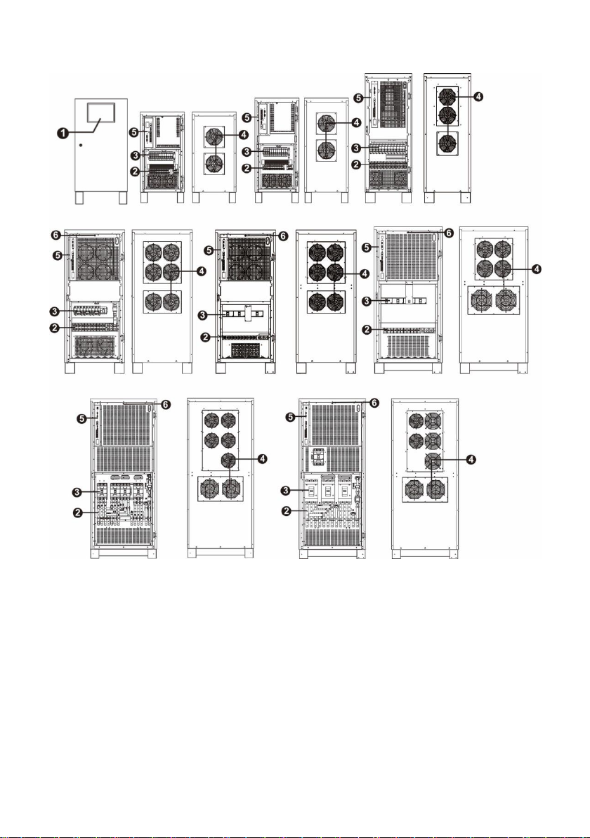
1.4 Overview
160K 200K
1) Interface 4) Fans
2) Terminals 5) Communications
3) Breaker and switch 6) Cold start button. This button is located same
position for whole series.
10K/15K/20K 30K 40K/60K
80K 100K 120K

6
2. Important Safety Warning
2.1 Conventions and used symbols
Conventions used:
WARNING! Warnings identify conditions or practices that could result in personal
injury;
CAUTION! Caution identify conditions or practices that could result in damaged to the
unit or other equipment connected.
Warning, risk of electric shock
Warning, risk of danger
Warning, risk of electric shock, energy storage timed discharge
Refer to the operating instructions
Warning, danger of the possible fall down of the equipment
Warning, Danger of fan’s rotation.
Warning, hot surface
Protective conductor terminal
Earth (ground) terminal
Direct current
Alternating current
Both direct and alternating current
Three-phase alternating current
Three-phase alternating current with neutral conductor
Preservation of the environment: the users can contact with their
provider or with the pertinent local authorities to be informed on how
and where they can take the product to be recycled and/or disposed
correctly.

7
2.2 Safety instructions
WARNING! Before installing and using this equipment, read all instructions and
cautionary markings on the UPS and this manual. Store the manual where it can be
accessed easily.
WARNING! This manual is for qualified personnel. The tasks described in this manual
may be performed by qualified personnel only.
WARNING! This equipment must be installed by qualified person.
WARNING! An earth cable whose cross section should be the same as or greater than
the power supply cable has to be connected to the protective earth connection.
WARNING! Make sure the UPS is isolated and protective earth correctly connected at
installing and before operating the UPS.
CAUTION! This UPS should use for an IT distribution system.
CAUTION! The UPS’s output neutral is same as the input neutral(Non isolate type). For
the correct operation of the UPS, the input neutral cable should be connected. It may
cause power loss without input neutral.
CAUTION! Please transport the UPS with packaged from factory.
WARNING! Pay attention to the slope of the ground and surface to avoid fall down
when moving the equipment.
WARNING! This equipment is heavy. Do not lift too heavy without help.

8
CAUTION! The UPS can only working on dry condition. Shut down the UPS if any liquid
flows into the UPS and dry it with absorbent cloth. Please use dry cloth when clean the
UPS.
CAUTION! Please charge the battery first if using the UPS for first time or no using the
UPS for a long period of time (6 months maximum).
WARNING! Never manipulate the equipment with wet hands.
CAUTION! To avoid a risk of fire and electric shock, make sure that existing wiring is in
good condition and that the wire is not undersized. Do not operate the Inverter with
damaged or substandard wiring.
WARNING! When the UPS shut down the power supply to the load because of EPO
signal trigger, the equipment has power supply yet. To shut down the equipment’s power,
please turn off all the input power.
WARNING! Authorized service personnel should reduce the risk of electrical shock by
disconnecting both the AC and DC power from the UPS before attempting any
maintenance or cleaning or working on any circuits connected to the inverter. Turning off
controls will not reduce this risk. Internal capacitors can remain charged after
disconnecting all sources of power.
CAUTION! Do not open, disassemble or modify the equipment yourself. It contains no
user-serviceable parts. Attempt to service this equipment yourself may cause a risk of
electrical shock or fire and will void the warranty from the manufacturer.
CAUTION! Shut down the UPS If any smoke or gas exhausts from the UPS.
WARNING! Battery circuit is not isolated; it is dangerous to touch any part of the
batteries.
9
CAUTION! When batteries are replaced, the complete battery set has to be replaced
and do not reuse faulty batteries.
CAUTION! Do not expose the batteries in a fire or to high temperatures. Batteries may
explode.
CAUTION! Batteries involve a serious risk for health and environment. Their disposal
should be done in accordance with the existing regulations.
WARNING! Under high temperature environment, the case of this equipment could be
hot enough to cause skin burns if accidentally touched. Ensure that this inverter is away
from normal traffic areas.
CAUTION! Use only recommended accessories from installer. Otherwise, not-qualified
tools may cause a risk of fire, electric shock, or injury to persons.
CAUTION! To reduce risk of fire hazard, do not cover or obstruct the equipment.

10
3. Installation
3.1 Basic requirement
Ambient temperature: 0°C~+55°C
Storage temperature: -15ºC ~ 60ºC
Relative humidity: 5% ~ 95%
Altitude: If the UPS is installed within 1000m, the UPS power will not be derated.
When the height is over 1000m, the output power will be derated by following the
table.
Altitude(m)
1000
1500
2000
2500
3000
3500
4000
4500
5000
Coefficient
100%
95%
91%
86%
82%
78%
74%
70%
67%
Vertical: No vibration and the degree of deviation from vertical shouldn’t be more
than 5°.
Space: It’s requested to have a clearance of approx. 80 cm to the front and back of
the unit and approx. 50 cm to the side.
The UPS should be installed in the environment with free ventilation, less dust, optimum
ambient temperature and humidity.
The recommended ambient temperature is 20°C~25°C with 50% humidity.
Caution! It’s NOT allow to have flammable, explosive or corrosive gas or liquid in
installation environment. It is forbidden to install in a metal conductive dust
environment.

11
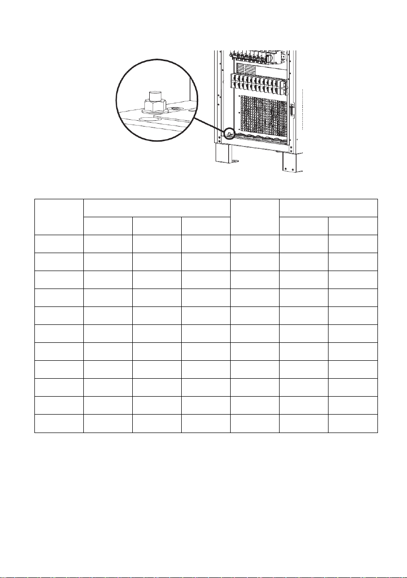
3.2 Disassembling and moving
Please check if any damage on the carton before open.
Then follow below steps to remove UPS from the carton and the pallet.
Remove the cartons and foam.
Remove the nuts showed in the figure.
Preparing two cables. The length of two cables is about 3 meters and the bearing should
be at least 1.5 tons. Fix the UPS with cables. Use the hoist to lift up the UPS and place it
on the ground.

12
After the UPS is removed from pallet, please inspect the unit and package contents.
Be sure that nothing inside the package is damaged. You should have received the
following items inside of package:
CD
User manual
USB cable
RS-232 cable

13
4. Electrical connection
4.1 Power connection
All the connectors are accessible by front panel of the UPS. Simply open the front door
for wire connection. Refer below diagrams for inside panel for whole series.
160K 200K
80K 100K 120K
10K~20K 30K 40K~60K
14
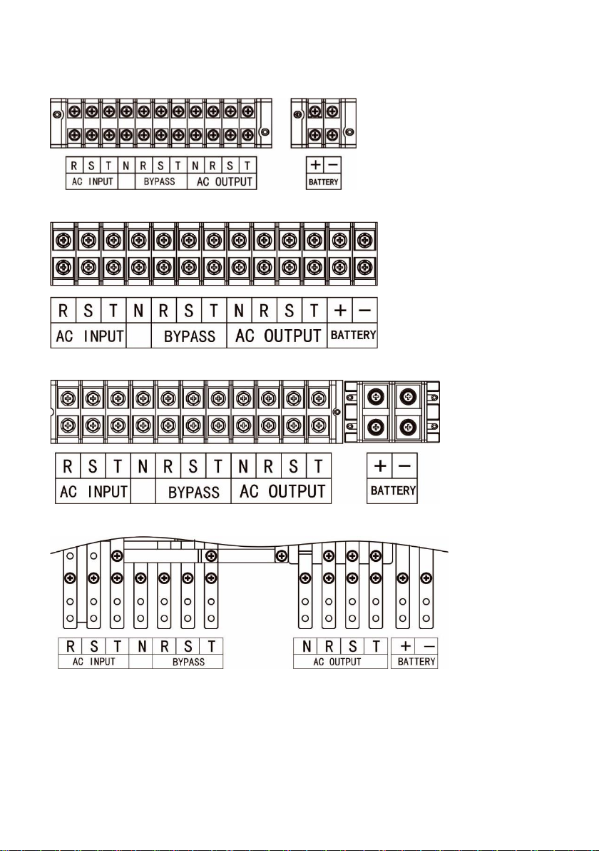
The wire terminals of each model are shown as below:
10K~30K
40K~60K
80K~120K
160K~200K
15
The ground terminal is shown as below:
The specifications of internal breaker, fuse and switch are shown as below:
UPS
Model
Input Breaker
Battery
Fuse
Output
LINE INPUT
BYPASS
M-BYPASS
Breaker
Switch
10K
63A/3P
63A/3P
63A/3P
100A
63A/3P
N/A
15K
63A/3P
63A/3P
63A/3P
100A
63A/3P
N/A
20K
63A/3P
63A/3P
63A/3P
100A
63A/3P
N/A
30K
63A/3P
63A/3P
63A/3P
200A
63A/3P
N/A
40K
100A/3P
100A/3P
100A/3P
200A
N/A
125A/3P
60K
100A/3P
100A/3P
100A/3P
315A
N/A
125A/3P
80K
125A/3P
125A/3P
125A/3P
315A
N/A
125A/3P
100K
225A/3P
225A/3P
225A/3P
350A
225A/3P
N/A
120K
225A/3P
225A/3P
225A/3P
350A
225A/3P
N/A
160K
350A/3P
250A/3P
250A/3P
350A x 2
250A/3P
N/A
200K
350A/3P
350A/3P
250A/3P
350A x 2
350A/3P
N/A

16
The recommended sizes of the cables are listed as below:
UPS
Model
Line Input and Ground
BYPASS/OUTPUT
BATTERY
Size
(AWG)
Cross section
(mm2)
Size
(AWG)
Cross section
(mm2)
Size
(AWG)
Cross section
(mm2)
10K
≤ 10
≥ 6
≤ 10
≥ 6
≤ 8
≥ 8
15K
≤ 8
≥ 8
≤ 8
≥ 8
≤ 6
≥ 10
20K
≤ 8
≥ 8
≤ 8
≥ 8
≤ 6
≥ 10
30K
≤ 6
≥ 10
≤ 6
≥ 10
≤ 4
≥ 20
40K
≤ 4
≥ 16
≤ 4
≥ 16
≤ 2
≥ 30
60K
≤ 2
≥ 25
≤ 2
≥ 25
≤ 1/0
≥ 50
80K
≤ 1/0
≥ 40
≤ 1/0
≥ 40
≤ 3/0
≥ 80
100K
≤ 1/0
≥ 40
≤ 1/0
≥ 40
≤ 4/0
≥ 100
120K
≤ 3/0
≥ 80
≤ 3/0
≥ 80
≤ 4/0
≥ 100
160K
≤ 3/0
≥ 80
≤ 3/0
≥ 80
≤ 4/0
≥ 100
200K
≤4/0
≥100
≤4/0
≥100
≤4/0
≥100
The recommended sizes of the ring terminals are listed as below:
Items
10K-30K
40K-60K
80K-120K
160K~200K
AC INPUT/
BYPASS/
OUTPUT/
BATTERY
AC INPUT/
BYPASS/
OUTPUT/
BATTERY
AC INPUT/
BYPASS/
OUTPUT
BATTERY
AC INPUT/
BYPASS/
OUTPUT/
BATTERY
D (mm)
5.3
8.4
8.4
10.5
8.4
L (mm)
12
22
22
27
22
Torque (Nm)
2
5.5
5.5
10
5.5
Recommended battery pack capacity:
Model
10K/15K/20K
30K/40K
60K/80K
100K~200K
Battery capacity
100 Ah
200 Ah
400 Ah
600 Ah
Note 1: Please set up suitable charging current and battery numbers based on
specifications. Wrong configuration will shorten lifecycle of battery.
Note 2: The bypass input of the UPS is default connected to AC input wire from factory.

17
Therefore, if this UPS is used as dual-inputs, please cut this connection.
Note 3: If there is no neutral connection in bypass, the load with neutral connection may
be out of power when UPS is in bypass mode.
After connecting all the cables, please double check the issues as below:
Check the phase sequence of LINE INPUT, BYPASS and OUTPUT.
Check the polarity of the battery cables.
Make sure all the connected cables are screwed tightly.
4.2 Communication
The UPS provides a variety of communications. The details are listed as below:
4.2.1 Intelligent slot
The intelligent slot can provide SNMP solution for remote monitor. Please request the
supplier for detail information.
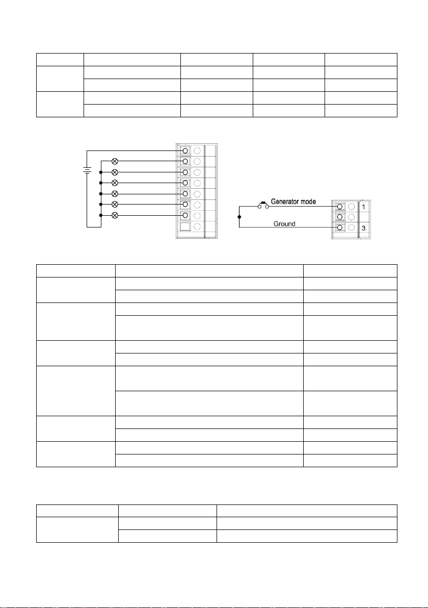
4.2.2 Dry contact
There are 6 output and 1 input dry contacts. The detailed functions are listed as below.
COMMON
UPS fault
UPS warning
Low battery
Line lost
Bypass mode
Inverter mode
Preserved
Ground
Remote turn on
Remote turn off
1
8
1
3
The output dry contacts only provide two passive statuses: short and open. It’s
necessary to connect external power source to trigger this function.
The input dry contacts provide active signals and it’s not necessary to connect external
power to trigger it. Users can simply short or open the ports to ground.
18
The detailed electrical parameters of contacts are listed as below:
Contacts
Parameters
Typical
Maximum
Unit
Output
Relay dc voltage
12
30
V
Relay dc current
0.5
1
A
Input
Output voltage
N/A
5
V
Output current
N/A
15
mA
Application:
Common
UPS fault
UPS warning
Battery low
Line lost
Bypass mode
Inverter mode
Ground
Remote turn on
Remote turn off
+12V
1
8
1
3
Function descriptions of output contacts:
Output contacts
Description
Status
UPS fault
UPS works normally.
Open (Default)
UPS is fault.
Short
UPS warning
UPS works normally.
Open (Default)
UPS is in standby, bypass, fault, line loss or
low battery.
Short
Battery low
Battery voltage is normal.
Open (Default)
Battery voltage drops to low alarm point.
Short
Line lost
Line voltage and frequency is under normal
range.
Open (Default)
Line voltage and frequency exceeds normal
range.
Short
Bypass mode
UPS isn’t in bypass mode.
Open (Default)
UPS is in bypass mode.
Short
Inverter mode
UPS isn’t in line or battery mode.
Open (Default)
UPS is in line or battery mode.
Short
Function descriptions of input contacts:
Input contacts
Status
Description
Generator mode
Open (Default)
No action
Short
UPS will work on generator mode.
This manual suits for next models
11
Table of contents


