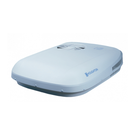
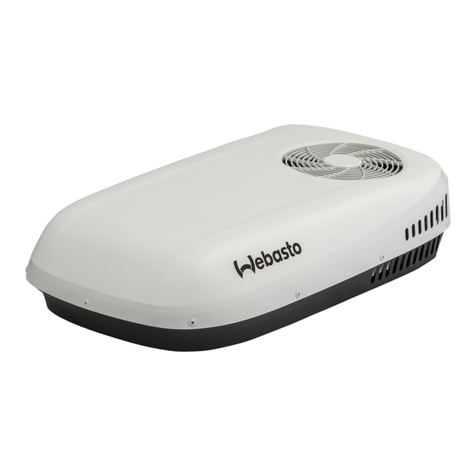
Houghton BELAIRE T135C User manual

1
.

Safety Notices
Dear user, thank you for choosing a HOUGHTON caravan air-conditioner. For your
ease of use and safe maintenance, we have included the following symbols in this manual:
All the contents with this “Prohibition”logo are about the actions that
shall be prohibited, or else the machine may be damaged, or the user’s
personal safety may be endangered.
All the contents with this “Warning”logo are about the safety of the
product and the user, the user shall operate in strict compliance with the
instructions.

Table of Contents
Safety Notes ..........................................................................................................................................1
Product Introduction ..............................................................................................................................2
Packing List...........................................................................................................................................3
Installation Guidance .............................................................................................................................4
Instructions for Use..............................................................................................................................10
Operation Instruction .........................................................................................................................11
Product Maintenance .........................................................................................................................116
Specification Parameters......................................................................................................................17
Exploded Diagram and Parts List.........................................................................................................18
Trouble Shooting Guide.......................................................................................................................20
Circuit Diagram...................................................................................................................................21

1
Safety Notes
Keep the inlet and outlet of the inside and outside units of the caravan air conditioner
smooth.
Do not spray any paint or insecticide on the surface of the air-conditioner.
Immediately turn off the air-conditioner and isolate power supply if there is any unusual
odor, smoke or fire detected, Contact after-sales-service personnel in case of unit fault and
fire.
Make sure the external electric supply socket of the caravan air-conditioner is
effectively grounded in accordance with your local regulations. Failure to ground the
unit correctly may cause electric shock or fire.
The caravan air-conditioner shall be switched on for electric leakage detection after
installation.
If you are not to use the air-conditioner for a long time, please isolate the power
supply.
Clean the filter of the air-conditioner regularly, A dirty filter will decrease air flow and
lead to poor heating and cooling performance.
Use the remote controller to operate the air-conditioner.
Install the air-conditioner in compliance with the instructions of this manual. Incorrect
installation methods or alteration of the product may cause damage to the product or
personal injuries to the user.
Be careful when installing the unit on the roof of the caravan, crawl boards may be
required.
There may be wires between the roof and the ceiling. When cutting into the roof,
make sure the power is isolated prevent risk of electric shock.
Installation and maintenance of the air-conditioner must only be performed by
personnel with appropriate trade qualifications and holding current licenses for such
work.
Do not over-tighten the power connection terminals.
Do not put hand into discharge duct during installation as this may damage the foam
coil tray.
Ensure that your electrical supply and wiring is correctly sized for the power demand
of the air-conditioner. Refer to the specification requirements of the product.
This appliance is not to be used by persons (including children) with reduced
physical, sensory or mental capabilities, or lack of experience and knowledge, unless
they have been given supervision or instruction. Children being supervised not to play
with the appliance.

2
Product Introduction
A. Purpose
HOUGHTON BELAIRE is designed to provide a comfortable environment inside a recreational vehicle or
caravan.
B. How to provide an efficient operation
Many factors will affect the total heat load within the caravan and many factors can also affect the working
efficiency of the air-conditioner. Before purchasing HOUGHTON BELAIRE, the user shall consult with the caravan
manufacturer to understand the total heat load of the caravan and to choose the correct air-conditioner for the
application.
The following measures are very useful to reduce the heat load within a caravan or RV and improve the
performance of the air-conditioner.
Close all the doors, skylights and windows, draw the curtains, and open the sunshade.
Adjust the caravan’s position to make sure the sunshade is on the southern side in the northern hemisphere or on
the northern side in the southern hemisphere. This will reduce the exposure to direct sunshine.
Turn off the unnecessary electrical appliances within the caravan to reduce the heat-load.
Please cook outside of the caravan.
Park the caravan at a shade place.
In case of exceptional high temperature, turn on the air-conditioner in advance during the morning.
Adjust the set temperature of the remote control to prevent from frequent start or stop of the unit.
C. Condensation
For the areas where the air humidity is comparatively low, when the warm moist air within the caravan meets with
the cold wind from the outlet, condensate water may be caused, which is also called as “sweating”. In this case, make
sure the following measures are taken:
Close all the doors, skylights, windows and draw the curtains to reduce the warm moist air incoming.
In the operation of the air-conditioner, a large number of condensate water will be produced on the roof as the
warm moist air is exhausted by the operation of the air-conditioner. The size of the condensate water is decided by
the air humidity. In this case, do not adjust the FAN to low or auto mode but adjust it to high FAN mode to
increase the circulation of the air and reduce the condensation degree.
Please be noted that losses caused by the condensate water are not within warranty scope.
D. Choosing and using of generator
HOUGHTON BELAIRE requires an AC power source and may require for generator driving in some remote areas.
Requirements for generator include efficient power source, stable currency, output power ≥2800W, output waveform:
sine wave, that shall meet the driving requirements of the compressor. The user shall consult with the generator supply
and fully refer to their suggestions.
Please be noted that losses caused to the product by the using of the generator are not within warranty scope.
3
Packing List
Installation parts list
Main parts:
1.BELAIRE air-conditioner outdoor unit ×1
2.Outlet gasket ×1
3.Outlet air duct ×1
4.Plenum mounting bracket ×1
5.Return air filter ×2
6.Plenum assembly ×1
7.M8x120mm blots ×4
8.Fixing metal plate ×4
9.Large washer x4
10.Flat head screw x8
11.Pan head tapping screw ×4
12.Countersunk head tapping screw ×6
7 8 9
10 11 12
1
2
4
5
6
3

4
Installation requirements
The RV or caravan roof shall be able to support the air-conditioner’s weight (40kg).
The opening part of the roof shall be able to support the air-conditioner’s weight and allow for the
corresponding operations.
Minimum thickness of roof: ≥25mm; maximum thickness of roof: ≤85mm。
If the roof’s thickness is beyond the above requirements, you can purchase the enhanced length of the
outlet air duct and M8 installation bolts from HOUGHTON or the local distributor.
schematic diagram after fixing the blocks
Roof
Block
Installation Guidance
Load bearing of roof
The roof shall be able to bear the weight of the
air-conditioner and shall be level without accumulating
water. It is suggested that the caravan manufacturer
confirms the suitability of the roof for load bearing.
If the roof is not preserved with holes, they shall be
punched from the top of the roof to the inside and use
them as leading to punch through the ceiling. It is
suggested to consult with the caravan manufacturer to
get the best punching method.
The square holes (360 x 360mm) on the roof require
for woods of 20mm minimum thickness to padding
and fixing to bear the pressure once the bolts are fixed
and keep air away from entering the cavity of the roof.
Please be careful of the preserved wire holes.
Block
Block
Installation instructions
Read this Manual thoroughly before installation and understand the guidance.
Abide by the national circuit operation rules in the installation.
Do not add other parts or restructure the product in the installation.
The installers shall be equipped with refrigeration technician qualification certificates.
Consult with HOUGHTON or the local distributor in the case of unusual applications or installation
conditions that are not specifically covered by this manual.
Roof
Block

5
Installation position
Note
Angle of inclination of the air-conditioner shall not be larger than 5° and the back part of the
air-conditioner shall not be higher than the front part.
If advice on installations outside of these limits, please contact with the local distributor.
Square hole(360X360mm)
Plenum position
Position of rooftop unit
Moving direction of caravan
Before the installation, consider the installation position:
At least 150mm is needed on the left and right side.
At least 200mm is need at the front and back area.
At least 50mm is needed for the height.
Rooftop unit is to be put in the center of the roof to
ensure the balance of air flow.
The direction of the rooftop unit should be the same
with moving direction of a caravan, otherwise, it will
cause damage of outdoor fan.
It’s suggested to install 2 or more units on a caravan
which is more than 7 meters long to achieve desired
cooling effect.
Please confirm position of rooftop unit as per below
drawing and check the position of plenum in the inside
of caravan.
Position of rooftop unit should avoid partitions,
cupboards or lights to make air flow go smoothly.
Moving direction of caravan
Fron
t
Back

6
Install outlet gasket
Mare sure the roof is dry, clean and without oil before installation.
Take off the paper from the back of the outlet gasket and stick the outlet gasket onto the roof over the square hole.
Press the outlet gasket to make sure the outlet gasket is closely adhered to the roof.
Fill the silicon glue around the outlet gasket to make sure no leakage happens. Please note the silicon glue can’t touch
the rooftop unit.
Place the outdoor unit over the outlet gasket and adjust position to make sure the 4 bolts under the outdoor unit are
aligned with the 4 corners of the square hole(360x360mm). When position of outdoor unit is being adjusted, a person
needs to go to the inside of caravan to ensure the alignment.
Do not push or pull the outdoor unit directly, otherwise, it will cause damage to the outlet gasket and lead leakage of air
and water.
The 4 holes which receives M8 bolts on the base of the outdoor unit should align with the 4 corners of the square
hole(360x360mm) on the roof.
Install outdoor unit
The silicon glue should
go in a close circle

7
Note
Match the corresponding active (brown), neutral (blue)
and the ground wire (yellow green) and firmly tighten up
the screws to make sure the power line is not loose or
improperly connected, otherwise a short circuit or fire
could be caused.
Connect the power
Cut the 4 cable ties and fix the outlet air duct to the
outdoor unit from inside of caravan using 4 flat head
screws. (This step can be done before installing outdoor
unit, but please note do not damage the outlet air duct).
Pay attention to the local wiring regulations that need
to be followed when connecting to main supply.
Look upward from inside the caravan, and locate the
terminal block as shown in the figure.
Connect the external power lines to the 3-pole terminal
block and note the positions of the active, neutral and
ground.
3 Pole terminal block
Install outlet air duct
Note
The outlet air duct has the up and
down, left and right direction, only
one way to be connected correctly,
please align and connect.
This face down
Flat head screw.

8
Install plenum mounting bracket
Connect outlet air duct
Overlap M8 bolt with washer and fixing metal plates
and get bolts through the 4 holes on corners of the
plenum mounting bracket.
Make sure fixing metal plates is 10mm distance from
the plenum mounting bracket in order to adjust angle
during installation.
Push the plenum mounting bracket upward to snap into
the square hole.
Tighten M8 bolt to make sure the plenum mounting
bracket is connected with outdoor unit tightly.
It’s suggested that when screwing the bolt, torque
should be 7N.M which could make the connection
between outdoor unit and outlet gasket perfect.
Check if the plenum mounting bracket is completely
embedded into the square hole.
Snap the outlet air duct into the square hole on the plenum mounting bracket. Four fixed hole position is naturally aligned.
Screw the outlet air duct with the plenum mounting bracket with 4 flat head screws from underneath the plenum mounting
bracket support the square duct ring by hand when screwing.
Flat head screw
Fixed Hole
Square duct
ring

9
Install plenum assembly
Connect the socket and plug of the display panel wires
and the controller wires; please notice that colors of
the wires should be matching (yellow to yellow, red to
red, etc.);
Attach the plenum assembly to the plenum mounting
bracket by engaging the two parts. You will hear four
clicks to as the parts connect together;
Fix the plenum assembly on the plenum mounting
bracket with 4 provided pan head tapping screws.
Take out the return air filter and fix the plenum to the
ceiling with 4 provided countersunk head tapping
screws.
Finally, fit both return air filter into the plenum
properly and the installation is all completed.
Plenum mounting
bracket
Plenum assembly

10
Note
After selecting the COOL/HEAT mode, the compressor will have a delay
start for three minutes.
Instructions for Use
Switch on the power to the air-conditioner at the isolation breaker.
Start the air-conditioner by switching to FAN mode to select the FAN.
Operate in low FAN, medium FAN and high FAN in turn to check normal operation.
To select the COOL mode, adjust the set point temperature to three degrees lower than the room
temperature, the unit will start to blow cold air after the compressor starts.
To select the HEAT mode, adjust the set point temperature to three degrees higher than the room
temperature, the unit will start to blow hot air after the compressor starts.

11
Operation Instruction
Remote controller
Plenum display
Touch screen key
Temperature
display
Mode display

12
1. Operation of the remote controller
Turn on
Press the on/off “” key, the machine turns on, the buzzer of the plenum beeps one time and the running mode and
temperature will be displayed.
FAN mode
Press the “MODE”key, select the “” mode, Press the“FAN”key,Select Low/Medium/High FAN circularly and
the plenum will display “”and the indoor environment temperature.
Low Medium High
COOL mode
Press the“MODE”key, select the mode, Press the down“▼”key to set the temperature lower than the room
temperature ,Press the“FAN”key to select different speed. and the plenum will display and the setting temperature.
FAN
FAN

13
DRY mode
Press the“MODE”key, select the“”mode, Press the down“▼”key to set the temperature 1℃lower than the room
temperature , and the plenum will display and the setting temperature.
HEAT mode
Press the “MODE” key, select the mode, Press the up“▲”key to set the temperature higher than the room
temperature ,Press the“FAN”key to select different speed. and the plenum will display and the setting temperature.
AUTO mode
Press the “MODE” key, select the“”mode, Press the up“▲”or down“▼”key to set different temperature ,Press
the“FAN”key to select different fan speed. and the plenum will display and 、or and , and
the setting temperature.
FAN
FAN

14
Celsius and Fahrenheit degree change
In any mode,Press the“℃/℉”key,you can select temperature between Celsius and Fahrenheit.
Turn off
Press the on/off“”key again,unit turns off and the plenum will display nothing.
Note
When in the AUTO mode, according to the difference between the setting temperature and the
environmental temperature , the plenum will display“”and “”(automatic heating) , or
“”and “”(automatic cooling) in the same time.

15
Note
In case the plenum touch screen key is locked by the remote controller, operations of the key would
be not available. Press the lock key on the remote controller again to unlock!
2. Plenum operation
Press the touch screen “ ” key on the plenum, the setting will be circularly from “ OFF ->COOL ->FAN
->HEAT” modes for every pushing. The setting temperature is 24℃ in high fan FAN.
Mode display of the plenum are as: COOL “”, DRY , FAN“”, HEAT“”, AUTO“”.
Tips
When in the automatic mode, according to the difference between the setting temperature and
the environmental temperature , the panel will display and (automatic
heating) , or and (automatic cooling) in the same time.
The remote controller should be operated by directing at the plenum, which will beep once
when received signal, otherwise operate after adjusting the distance and angle.
The unit will blow cold air in COOL mode and hot air in HEAT mode.
When the unit is on, press the “DISPLAY” key on the remote controller, the control plenum
LED display will be on and off.
When the unit is on, press the “LOCK” key on the remote controller to shield and invalidate
the touch screen key on the plenum.
The air-conditioner features power cut memory and automatic starting-up after power back
functions.
Low temperature heating will cause frosting, during when it is normal to show “DF” on the
plenum.
When the environmental temperature is lower than 0℃, the heating effect is reduced, suggest
adopting other ways for heating in the same time.
If the device is left unused for long time, please remove the batteries from the remote
controller.

16
Maintenance
It is recommended that the air-conditioner is operated regularly to ensure good performance.
In the case of a caravan that will not be used regularly then the unit should be operated for 20-30
minutes every 6 months.
In case the caravan is parked outdoors for long time, suggest to use protective jacket to protect the
outdoor unit of the air-conditioner from wind and sun.
Bolt check
It is recommended that the bolts holding the unit to the roof are checked for tightness 3 months after
the first installation of the product.
These bolts should be regularly inspected every 12 months through-out the air-conditioners life.
Filter
The return air filters are the only components that need to be maintained periodically.
Check and clean the filter screen each week when in use to prevent the filter from being blocked
by dirt.
The filter should be washed frequently to ensure effective cooling and heating.
Pull out the filter from the panel before washing in warm water with a touch of detergent.
Replacement filters can be ordered separately.
Product Maintenance

17
Specification Parameters
Model
T135C
T150
T3500
Power supply
115V~/60Hz
115V~/60Hz
220-240V~/50Hz
Refrigerant charged
R410A/470g
R410A/650g
R410A/590g
Rated cooling capacity
13500BTU/H
15000BTU/H
3500W
Rated heating capacity
-------
15000BTU/H
3500W
Input power for cooling (W)
1300
1500
1300
Input power for heating (W)
-------
1300
1200
Rated current for cooling(A)
12
14
5.6
Rated current for heating(A)
-------
12
5.2
Maximum input power(W)
1550
1750
1500
Maximum current(A)
14
16
6.5
Maximum design pressure(kPa)
4500
4500
4500
Minimum design pressure(kPa)
3000
3000
3000
Maximum air flow(l/s)
165
165
150
Installed weight(kg)
33.5+2.8
36.5+2.8
35.5+2.8
Outdoor unit dimension Height 340mm Width 680mm Length 998mm
Plenum unit dimension Height 43mm Width 536mm Length 557mm
Notes: 1.All parameters listed are subject to change without notice and the nameplates on the machine
shall prevail;
2. E&OEAll values are approximate & subject to change.
This manual suits for next models
2
Table of contents
Other Houghton Air Conditioner manuals

Houghton
Houghton BELAIRE H2000 User manual

Houghton
Houghton H2000C User manual

Houghton
Houghton A3501 User manual

Houghton
Houghton BELAIRE H2000 User manual

Houghton
Houghton BELAIRE HB3400 User manual

Houghton
Houghton BELAIRE H2400D User manual

Houghton
Houghton BELAIRE User manual

Houghton
Houghton BELAIRE User manual

Houghton
Houghton Cool Top Trail 34 User manual

Houghton
Houghton BELAIRE H3400 User manual