Houston M741LMRT User manual

This publication, including all photographs, illustrations and
software, is protected under international copyright laws, with all
rights reserved. Neither this manual, nor any of the material
contained herein, may be reproduced without the express written
consent of the manufacturer.
The information in this document is subject to change without
notice. The manufacturer makes no representations or warranties
with respect to the contents hereof and specifically disclaims any
implied warranties of merchantability or fitness for any particular
purpose. Further, the manufacturer reserves the right to revise this
publication and to make changes from time to time in the content
hereof without obligation of the manufacturer to notify any person
of such revision or changes.
Trademarks
IBM, VGA, OS/2, and PS/2 are registered trademarks of
International Business Machines.
Intel, Pentium, Pentium-II, MMX, and Celeron are registered
trademarks of Intel Corporation.
Microsoft, MS-DOS and Windows 95/98/NT are registered
trademarks of Microsoft Corporation.
Sound Blaster and SB-Link are trademarks of Creative Technology
Ltd.
PC-cillin and ChipAway Virus are trademarks of Trend Micro Inc.
AMI is a trademark of American Megatrends Inc.
A3D is a registered trademark of Aureal Inc.
Gamut is a registered trademark of Formosoft International Inc.
SuperVoice is a registered trademark of Pacific Image
Communications Inc.
MediaRing Talk is a registered trademark of MediaRing Inc.
Other names used in this publication may be trademarks and are
acknowledged.
Copyright © 1999
All Rights Reserved
M741LMRT, Version 1.4
S6X/April 1999

Federal Communications Commission (FCC)Federal Communications Commission (FCC)
This equipment has been tested and found to comply with the limits for a
Class B digital device, pursuant to Part 15 of the FCC Rules. These limits
are designed to provide reasonable protection against harmful interference
in a residential installation. This equipment generates, uses, and can
radiate radio frequency energy and, if not installed and used in accordance
with the instructions, may cause harmful interference to radio
communications. However there is no guarantee that interference will not
occur in a particular installation. If this equipment does cause harmful
interference to radio or television reception, which can be determined by
turning the equipment off and on, the user is encouraged to try to correct
the interference by one or more of the following measures:
qReorient or relocate the receiving antenna.
qIncrease the separation between the equipment and the receiver.
qConnect the equipment onto an outlet on a circuit different from that
to which the receiver is connected.
qConsult the dealer or an experienced radio/TV technician for help.
Shielded interconnect cables and shielded AC power cable must be
employed with this equipment to insure compliance with the pertinent RF
emission limits governing this device. Changes or modifications not
expressly approved by the system’s manufacturer could void the user’s
authority to operate the equipment.
Declaration of Conformity
This device complies with part 15 of the FCC rules. Operation is subject
to the following conditions:
qThis device may not cause harmful interference, and
qThis device must accept any interference received, including
interference that may cause undesired operation.
Canadian Department of CommunicationsCanadian Department of Communications
This class B digital apparatus meets all requirements of the Canadian
Interference-causing Equipment Regulations.
Cet appareil numérique de la classe B respecte toutes les exigences du
Réglement sur le matériel brouilieur du Canada.

Table of Contents
Chapter 1 Introduction...............................................................1
Key Features................................................................................................2
Slot-1 Processor Support......................................................................2
Socket-370 Processor Support.............................................................2
Memory Support....................................................................................2
Expansion Slots......................................................................................2
Onboard IDE channels..........................................................................2
Power Supply and Power Management .............................................2
Built-in Graphics System.....................................................................3
Sound System.........................................................................................3
Onboard I/O Ports..................................................................................3
Hardware Monitoring............................................................................4
Built-in LAN Adapter...........................................................................4
Fax/Modem DAA Module...................................................................4
OnboardFlashROM.............................................................................4
Bundled Software ..................................................................................4
Dimensions.............................................................................................5
Package Contents........................................................................................5
OptionalAccessories.............................................................................5
Static Electricity Precautions....................................................................6
Chapter 2 Mainboard Installation................................................7
Mainboard Components.............................................................................8
I/O Ports .......................................................................................................9
Install the Processor....................................................................................9
Installing a Slot-1 Processor Cartridge............................................10
Installing a Socket-370 Processor.....................................................11
Install Memory ..........................................................................................12
Set the Jumpers..........................................................................................13
Jumper JP10: Keyboard Power On Selector...................................14
Jumper J9: Clear CMOS Memory ....................................................14
Jumper JP6: Enable/Disable Onboard LAN....................................14
Jumper JP7: Enable/Disable Onboard Audio..................................14
Jumper JP8: Enable/Disable Onboard Fax/Modem.......................15
Jumper J20: Select Slot-1 or Socket-370 Processor.......................15
Install the Mainboard ...............................................................................16
Install the Extension Brackets ................................................................18
LAN Adapter Extension Bracket......................................................18
Fax/Modem Module............................................................................18
Optional Extension Brackets...................................................................20
Digital Audio Extension Bracket......................................................20

Install Other Devices................................................................................21
Floppy Disk Drive ...............................................................................21
IDE Devices..........................................................................................21
Internal Sound Connections...............................................................22
Digital Audio Connection..................................................................22
Infrared Port..........................................................................................23
Expansion Slots .........................................................................................24
LAN Wake Up......................................................................................24
Chapter 3 BIOS Setup..............................................................25
Introduction................................................................................................25
Running the Setup Utility........................................................................26
Standard CMOS Setup Page ...................................................................27
Advanced Setup Page...............................................................................28
Power Management Setup Page.............................................................30
PCI / Plug and Play Setup Page..............................................................31
Load Optimal Settings .............................................................................32
Load Best Performance Settings............................................................32
FeaturesSetupPage..................................................................................33
CPU PnP Setup Page................................................................................34
Hardware Monitor Page...........................................................................35
Change Password......................................................................................36
Change or Remove the Password......................................................36
Exit ..............................................................................................................36
Chapter 4 Software & Applications ...........................................37
Introduction................................................................................................37
Bus Master IDE Driver.......................................................................37
USB Driver...........................................................................................37
Sound Driver.........................................................................................38
Graphics Drivers and Software .........................................................38
Fax/Modem Drivers and Software....................................................38
Network Adapter Driver.....................................................................38
BIOS Update Utility............................................................................38
PC-Cillin Software ..............................................................................38
ADCM Software ..................................................................................39
Using the PCI Sound Application..........................................................39
The Four Speakers System......................................................................40
SpeakerInstallation.............................................................................40
Speaker Position...................................................................................40
Mixer Setup...........................................................................................40
Demo ......................................................................................................41

Chapter 1
Introduction
This mainboard has a slot-1processor socket for an Intel
processor cartridge, and it also has a socket-370 for an Intel
PPGA (Plastic Pin Grid Array) Celeron processor. You can
install either one of these processors according to the power and
performance requirements that you need from your system. Note
that you cannot install two processors on this mainboard.
Slot-1 processors include the SEPP (Single Edge Processor
Package) Celeron, the Pentium-II, and the Pentium-III. Clock
rates run as high as 500 MHz. Socket-370 processors are the
PPGA Celeronwhich runs at clock rates up to 466 MHz. The
mainboard supports a system bus of 66 MHzor 100 MHz.
The mainboard uses the Xcel 2000 chipset which provides CPU
Plug & Play through firmware. The mainboard is highly integrated
and includes a built-in 64-bit AGP Graphics Accelerator, a built-
in PCI 3D Sound System, and a built-in 10BaseT/100BaseTX
Network Adapter. A V.90 Fax/Modem DAA module is also
shipped with the mainboard. In addition, it has a full set of ATX
I/O Ports including two PS/2 ports, two USB ports, a parallel port,
a serial port and a VGA port.
This mainboard has all the features you need to develop a powerful
multimedia workstation that is network ready, and has built -in
communications. The board is micro-ATX sizedand has power
connectors for ATX power supply units so it can be installed in a
micro-ATX case.

Key Features
This key features of this mainboard include:
Slot-1 Processor Support
♦Pentium-IIIsupport for 450 MHz and 500 MHz clock
rates
♦Pentium-II support for 233 MHz to 450 MHz clock rates
♦SEPP Celeron support for 266 MHz to 433 MHz clock
rates
♦Support for 66 MHz and 100 MHz FSB (Front Side Bus)
♦All processors configured by CPU Plug & Play
Socket-370 Processor Support
♦The PPGA Celeron provides Pentium-II performance with
integrated level 1 and level 2 cache memory
♦PPGA Celerons run from 300 MHz through to 466 MHz.
♦Supports a 66 MHz front side system bus
♦All Celerons are automatically configured using firmware
Memory Support
♦Three DIMM slots for SDRAM 168-pin memory modules
♦Support for 66 MHz & 100 MHz memory bus
♦Maximum installed memory can be 3 x 256 MB = 768 MB
Expansion Slots
♦One 32-bit PCI slot
♦One 8/16-bit ISA slot
Onboard IDE channels
♦Primary and Secondary PCI IDE channels
♦Support for PIO (programmable input/output) modes
♦Support for Bus mastering and UltraDMA 33/66 modes
Power Supply and Power Management
♦Provides ATX power connector

♦Support for Green PC standard, suspend switch, keyboard
power on/off
♦Supports Wake on Modem, Wake on LAN and Wake on
Alarm
Built-in Graphics System
♦Onboard 64-bit 3DAGP Graphics Accelerator
♦Complies with AGP Ver. 2.0 with built-in 8-way/16 entry
set-associative GART cache for AGP master
♦Shared memory architecture allows a maximum of 8 MB
main memory to act as frame buffer
♦Supports high resolutions up to 1600 x 1200 pixels
Sound System
♦Meets PC98 audio specification
♦Full duplex playback and recording with built-in 16-bit
CODEC
♦HRTF 3D professional audio supports both Direct Sound
3D® and A3D® compatible interface plus support for 4-
channel speakers
♦Drivers support DOS/Windows 95/98/2000/NT 4.0
♦Built-in 32 ohm earphone buffer and 3D surround
♦Provides MPU-401 Game/MIDI port and legacy Sound
Blaster 16 support
♦Downloadable Wave-table Synthesizer supports Direct
Music®
♦Digital Audio Interface (SPDIF In/Out) with 24-bit stereo,
44KHz sampling rate and measured 120dB audio quality
♦Stereo Mixer supports analog mixing from CD-Audio,
Line-In, and digital mixing from voice, FM/Wave-table and
digital CD-Audio
Onboard I/O Ports
♦Provides PC99 Color Connector for easy identification of
peripheral devices
♦Floppy disk drive port with 1Mb/s transfer rate
♦One serial ports with 16550-compatible fast UART
♦One parallel port with support for ECP and EPP

♦Two USB ports & two PS/2 ports
♦One infrared port
Hardware Monitoring
♦Built-in hardware monitoring for CPU temperature and fan
speeds
♦Supports AMI’s Desktop Client Manager (ADCM)
Built-in LAN Adapter
♦Onboard 10BaseT/100BaseTX LAN Adapter
♦LAN controller integrates Fast Ethernet MAC and PHY
compliant with IEEE802.3u 100BASE-TX, 10BASE-T and
ANSI X3T12 TP-PMD standards
♦Compliant with ACPI 1.0 and the Network Device Class
Power Management 1.0
♦High Performance provided by 100 Mbps clock generator and
data recovery circuit for 100 Mbps receiver
Fax/Modem DAA Module
♦56 Kbps Fax/Modem DAA module
♦Supports V.90, V.34, V.32bis, V.32, V.22bis, V.22
♦Supports Auto Fallback and MNP 5, V.42bis data compression
with 115200 compatible Virtual UART
♦Requires 16 MB RAM and WIN 95/98/NT
Onboard Flash ROM
♦Provides plug and play function for automatic CPU and
board configuration
♦Supports plug and play configuration of peripheral devices
and expansion cards
♦Built-in virus protection using Trend’s ChipAway Virus
which ensures that the entire boot process is virus protected.
Bundled Software
♦AMI Desktop Client Managersupports hardware
monitoring on stand alone systems or over a network
♦PC-Cillin provides automatic virus protection under
Windows 95/98

♦SuperVoice Fax/Modem software
♦Gamut 98 provides professional audio application included
MP3 playback
♦MediaRing Talk provides PC to PC base internet phone
communication
Dimensions
♦Micro-ATX form factor (22cm x 24.4cm)
Package Contents
Your mainboard package ships with the following items:
qMainboard
qThis User’s guide
qIDE cable
qFloppy diskette drive cable
qFax/Modem DAA module
qNetwork adapter extension bracket
qSupport software CD-ROM
Optional Accessories
You can purchase the following optional accessories for this
mainboard.
qDigital Audio extension bracket

Static Electricity Precautions
1. Components on this mainboard can be damaged by static
electricity. Take the following precautions when unpacking the
mainboard and installing it in a system.
2. Keep the mainboard, and other components, in their original
static-proof packaging until you are ready to install them.
3. During an installation, wear a grounded wrist strap if possible.
If you don’t have a wrist strap, frequently discharge any static
electricity by touching the bare metal of the system chassis.
4. Handle the mainboard carefully by the edges. Avoid touching
the components unless it is absolutely necessary. During the
installation lay the mainboard on top of the static -proof
packaging with the component side facing upwards.
5. Inspect the mainboard for any damage caused during transit.
Ensure that all the components that are plugged into sockets
are correctly seated.
6. If you suspect that the mainboard has been damaged, do not
apply power to the system. Contact your mainboard vendor
and report the damage.

Chapter 2
Mainboard Installation
To install this mainboard into your system, follow the procedures
in this chapter:
qIdentify the mainboard components
qInstall the correct processor
qInstall one or more memory modules
qVerify that any jumpers or switches are at the correct setting
qInstall the mainboard in the system chassis
qInstall any extension brackets or cables tothe mainboard
headers
qInstall any other devices and make the appropriate connections
to the mainboard headers.
Note: 1. Before installing the mainboard, you must ensure that
jumper J9 is set to the Normal setting. See this chapter for
information on locating J9 and changing the jumper setting.
2. While installing the mainboard, please make sure the AC
power cord is unplugged before the full system is installed
completely. Otherwise, it may destroy stuffs unpredictably, due to
the power-on trigger event of power management.

Mainboard Components
Use the diagram below to identify the major components on your
mainboard.
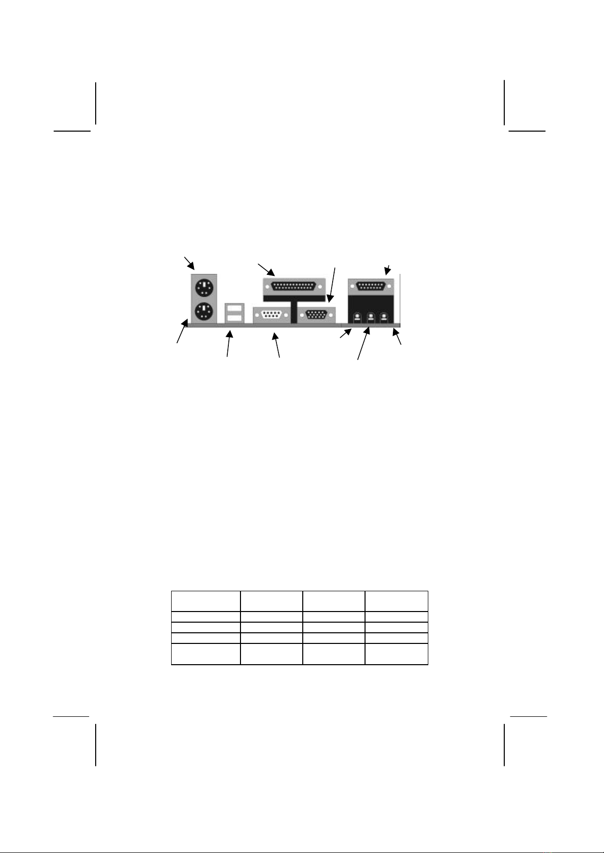
I/O Ports
The illustration below shows a side view of the I/O ports installed
on the mainboard.
PS/2 Mouse
PS/2 Keyboard
Parallel Port LPT1 Game/MIDI Port
Serial Port COM1/3USB Ports
Microphone Jack
StereoOut Jack
VGA Port
Stereo In Jack
Install the Processor
This mainboard has a Slot-1 which can be installed with any Slot-1
processor cartridge including the Pentium-III, the Pentium-II, and
the SEPP Celeron. It also has a Socket-370 which can be installed
with the new Celeron processor which is shipped in a PPGA
(Plastic Pin Grid Array) package. To ensure reliability, make
sure that your PPGA Celeron processor is fitted with a
heatsink/cooling fan assembly.
You can install a Slot-1 processor or a PPGA Celeron. You cannot
install a PPGA and a Slot-1 processor cartridge together. Take care
that you do not try to install a Socket-7 processor into the Socket-
370. A Socket-7 processor such as the Pentium-MMX, or the AMD
K5/K6 does not fit in the socket-370. The following table lists the
processors that are currently supported by this mainboard. New
processors may be a released after this manual is printed.
Processor
Cartridge Clock Rate
MHz Processor
Socket System Bus
MHz
Pentium-III 550 Slot-1100
Pentium-III 500 Slot-1100
Pentium-III 450 Slot-1100
Pentium-II 450 Slot-1100
Pentium-II 400 Slot-1100

Pentium-II 350 Slot-1100
Pentium-II 333 Slot-166
Pentium-II 300 Slot-166
Pentium-II 266 Slot-166
Pentium-II 233 Slot-166
SEPP Celeron 433 Slot-166
SEPP Celeron 400 Slot-166
SEPP Celeron 366 Slot-166
SEPP Celeron 333 Slot-166
SEPP Celeron 300A Slot-166
SEPP Celeron 300 Slot-166
SEPP Celeron 266 Slot-166
PPGA Celeron 466 Socket-370 66
PPGA Celeron 433 Socket-370 66
PPGA Celeron 400 Socket-370 66
PPGA Celeron 366 Socket-370 66
PPGA Celeron 333 Socket-370 66
PPGA Celeron 300 Socket-370 66
Installing a Slot-1 Processor Cartridge
1. Locate Slot-1, FAN1, and J20 on the mainboard.
2. The Slot-1 is installed with a cartridge holder. The upright
struts of the cartridge holder are folded down for shipping. Pull
the struts upwards so that they are in the upright position.
Slot-1 with pre-installed
cartridge holder. The
upright arms are folded
down for shipping.
FAN1
J20
1

3. Insert the processor cartridge into the cartridge holder. Follow
the instructions given with your processor cartridge. The edge
connector on the cartridge has a notch so that it only fits into
the Slot-1 in the correct way.
4. Locate the cooling fan power supply FAN1. Connect the cable
from the processor cartridge cooling fan to FAN1.
5. Locate the jumper J20. Use this jumper to short pins 2-3 if you
have installeda Slot-1 processor.
6. On this mainboard, you can configure the processor by
entering the correct settings in the BIOS setup utility.
Installing a Socket-370 Processor
The Celeron processor installs into the ZIF (Zero Insertion Force)
Socket-370 on the mainboard.
1. Locate the Socket-370, FAN1, and J20. Pull the locking lever
out from the socket and swing it to the upright position.
Socket-370
FAN1
J20
1
2. On the Celeron processor, identify the pin-1 corner by noting
that it has a slight bevel.
3. On the Socket-370, identify the pin-1 corner. The pin-1 corner
is on the same side as the locking lever, closest to the top of the
lever when it is in the locked position.
4. Match the pin-1 corners and insert the Celeron processor into
the socket. No force is required and the processor should drop
into place freely.
5. Swing the locking lever down and hook it under the catch on
the side of the socket. This locks the Celeron processor in the
socket.
6. Locate the jumper J20. Use this jumper to short pins 1-2 if you
have installed a Socket-370 processor.
7. If the Celeron processor is installed with a cooling fan
assembly, connect the cable from the fan to the CPU fan power
connector FAN1.
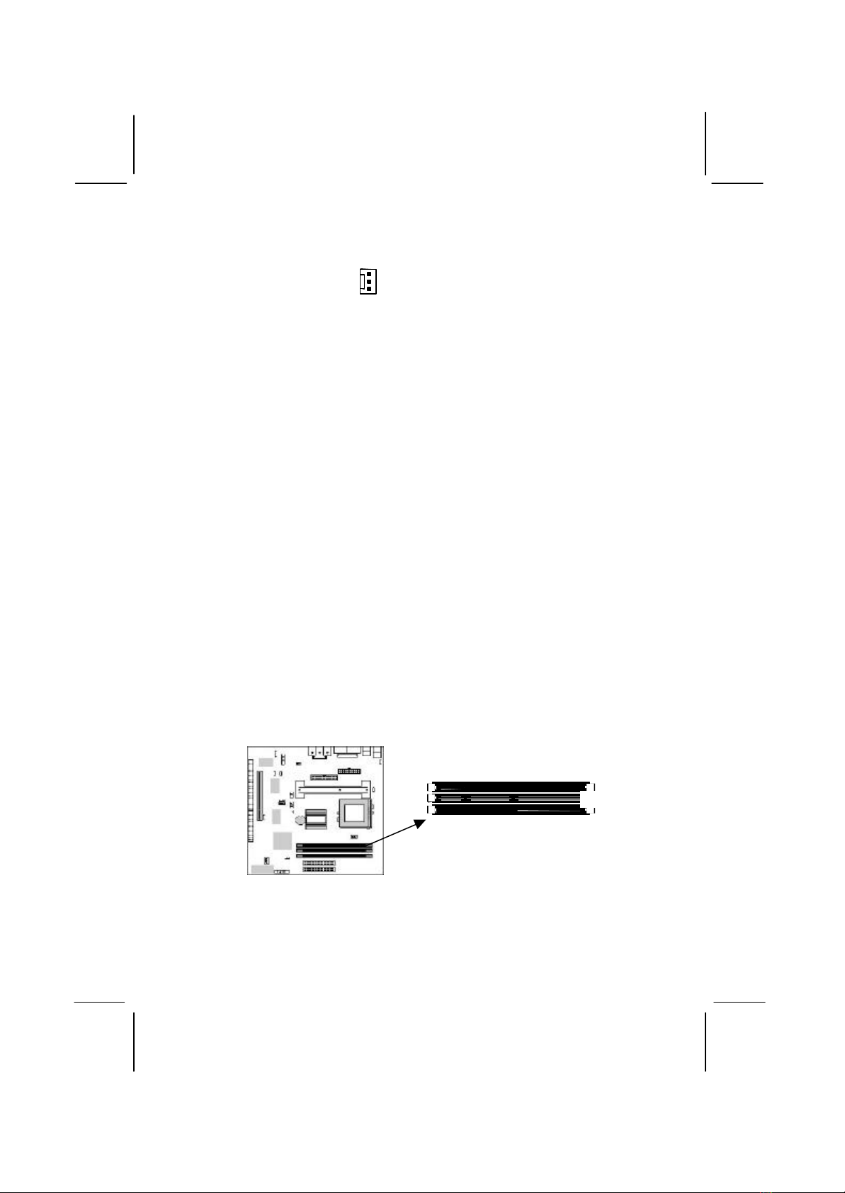
Install Memory
The mainboard has three DIMM slots which can be installed with
memory modules. You must install at least one memory module in
order to use the mainboard. You must install the first memory
module into DIMM1 so that it can share memory with the onboard
VGA system.
For this mainboard, you must use 168-pin, 3.3V memory modules
installed with SDRAM memory chips. If you are using a processor
DIMM1
DIMM2
DIMM3
Pin-1 Corner
that runs on a 100 MHz system bus, you must use memory that
operates on a 100 MHz memory bus (PC-100 memory). If you are
using a processor that runs on a 66 MHz system bus, you must use
memorythat operates on a 66 MHz memory bus. You can install
any size of memory module from 16 MB up to 256 MB, so the
maximum memory size is 3 x 256 MB = 768 MB.
The edge connectors on the memory modules have cut outs, which
coincide with struts in the DIMM slots, so the memory modules
can only be installed in the correct way.
On the DIMM slot, pull the locking latches at either end of the
slots outwards. Position the memory module correctly and insert it
into the DIMM slot. Press the module down into the slot so that the
locking latches lever inwards and lock the module in place.
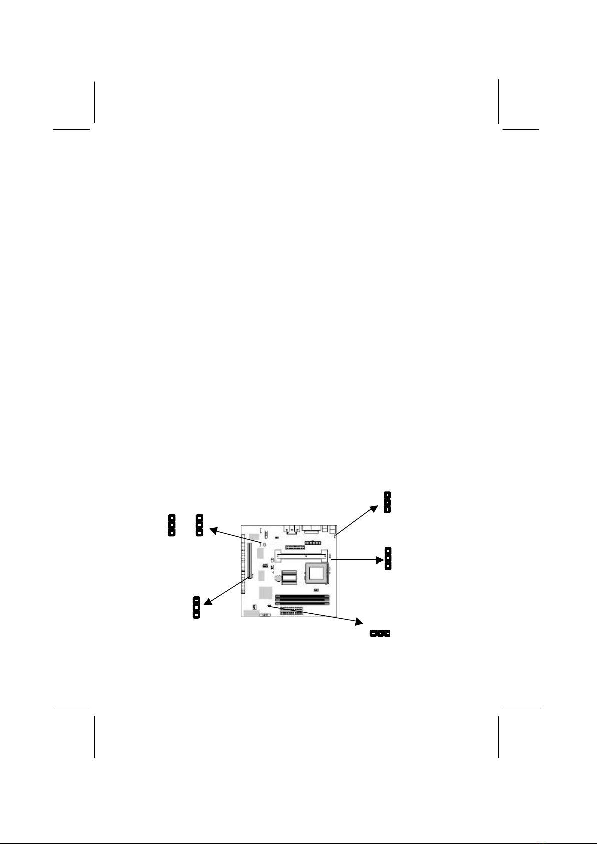
Set the Jumpers
Jumpers are sets of pins which can be connected together with
jumper caps. The jumper caps change the way the mainboard
operates by changing the electronic circuits on the mainboard. If a
jumper cap connects two pins, we say the pins are SHORT. If a
jumper cap is removed from two pins, the pins are OPEN.
J9
1
J10
1
J20
1
JP8
1
JP7
1
JP6
1

Jumper J10: Keyboard Power On Selector
If you enable the keyboard power on feature, you can use hot keys
on your keyboard as a power on/off switch for the system.
Note: Make sure that the system can provide 1A on +5VSB (+5V
Standby) signal before using the Keyboard Power On function.
Function Jumper Setting
Disable Keyboard Power On Short Pins 1-2
Enable Keyboard Power On Short Pins 2-3
Jumper J9: Clear CMOS Memory
Use this jumper to clear the contents of the CMOS memory. You
may need to clear the CMOS memory if the settings in the setup
utility are incorrect and prevent your mainboard from operating. To
clear the CMOS memory, disconnect all the power cables from the
mainboard and then move the jumper cap into the CLEAR setting
for a few seconds.
Function Jumper Setting
Normal Operation Short Pins 1-2
Clear CMOS Memory Short Pins 2-3
Jumper JP6: Enable/Disable Onboard LAN
Use this 3-pin jumper to enable or disable the onboard network
adapter.
Function Jumper Setting
Enable Onboard LAN Short Pins 1-2
Disable Onboard LAN Short Pins 2-3
Jumper JP7: Enable/Disable Onboard Audio
Use this 3-pin jumper to enable or disable the onboard audio
system. If you install a different audio system on an expansion
card, you must disable the onboard audio system. If you use this
jumper to disable the audio system, it automatically disables the
onboard Fax/Modem, even if the Fax/Modem jumper JP8 is
enabled.
Function Jumper Setting
Disable Audio/Modem Short Pins 1-2
Enable Audio Short Pins 2-3
Jumper JP8: Enable/Disable Onboard Fax/Modem
Use this 3-pin jumper to enable or disable the onboard
Fax/Modem. If the audio jumper JP7 is disabled, the Fax/Modem is
also disabled, no matter the setting of JP8.
Function Jumper Setting
Enable Onboard Modem Short Pins 1-2
Disable Onboard Modem Short Pins 2-3
J20: Select Slot-1 or Socket-370 Processor
Use this 3-pin jumper to prepare the mainboard to use either a Slot-
1 processor or a Socket-370 processor.
Function Jumper Setting
Socket-370 Processor Short Pins 1-2
Slot-1 Processor Short Pins 2-3
Install the Mainboard
Install the mainboard into the system chassis. This mainboard uses
the micro-ATX format with a twin-tier of I/O ports. Special micro-
ATX cases are available with a reduced number of expansion slots
and a smaller power supply unit. Ensure that your case has an I/O
template that can be used by this mainboard.
Install the mainboard into the unit case. Follow the instructions
provided by the case manufacturer using the screws and mounting
points provided in the chassis.
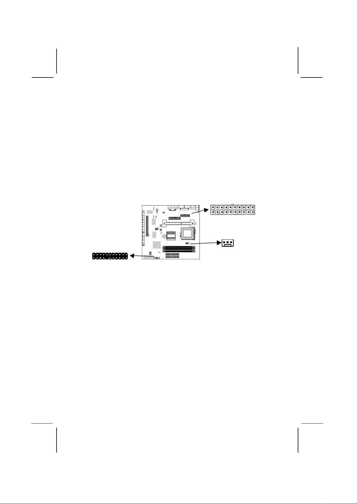
Connect the power cable from the power supply unit to the power
connector ATX Power on the mainboard. If the system chassis is
installed with a cooling fan, connect the cable from the cooling fan
to the chassis fan power connector on the mainboard FAN2.
ATX Power
J7
FAN2
Table of contents


