Hoval TopVent TG User manual

TopVent ®TG |GV |MG
Operating instructions
TopVent®
TG |GV |MG
Original operating manual
4 220 656-en-03

1 Use 3
1.1 Intended use .................................................................. 3
1.2 User group..................................................................... 3
2 Safety 4
2.1 Symbols......................................................................... 4
2.2 Operational safety.......................................................... 4
2.3 Decommissioning........................................................... 5
2.4 Emergency situations..................................................... 5
2.5 Regulations.................................................................... 5
3 Construction and operation 6
3.1 Components................................................................... 6
3.2 Function diagrams ......................................................... 7
4 Operating modes 8
5 Type code 10
5.1 TopVent®TG................................................................ 10
5.2 TopVent®GV................................................................ 10
5.3 TopVent®MG ................................................................11
6 Technical data 12
6.1 Application limits .......................................................... 12
6.2 Electrical connection.................................................... 12
6.3 Air ow rate, gas consumption ..................................... 12
6.4 Gas connection............................................................ 13
6.5 Sound levels ................................................................ 13
6.6 Heat output .................................................................. 13
6.7 Dimensions and weights .............................................. 14
7 Options 17
7.1 Outlet nozzle................................................................ 17
7.2 Suspension set ............................................................ 17
7.3 Air ltration................................................................... 17
7.4 Paint nish ................................................................... 18
7.5 Recirculation silencer................................................... 18
7.6 Acoustic cowl ............................................................... 19
7.7 Flue gas accessories ................................................... 19
8 Transport and installation 20
8.1 Scope of delivery ......................................................... 20
8.2 Storage ........................................................................ 20
8.3 Requirements for the installation site ........................... 21
8.4 Flue gas evacuation and combustion air supply........... 23
8.5 Installation.................................................................... 24
8.6 Gas connection............................................................ 25
8.7 Electrical installation .................................................... 26
9 Initial commissioning 28
9.1 Checklist to prepare for commissioning:....................... 28
9.2 Commissioning of the gas burner................................. 29
9.3 Service mode............................................................... 30
9.4 Emission measurement................................................ 30
9.5 Setting of the gas control valve.................................... 31
9.6 Programming the control system.................................. 31
10 Operation 32
11 Troubleshooting 32
11.1 Locking burner malfunctions....................................... 32
11.2 Temporary burner malfunctions .................................. 33
11.3 Warnings.................................................................... 33
11.4 Measures ................................................................... 34
11.5 Further troubleshooting .............................................. 35
12 Maintenance and repair 37
12.1 Safety......................................................................... 37
12.2 Maintenance .............................................................. 38
12.3 Repair ........................................................................ 39
13 Changing the type of gas 39
13.1 Switching to a different type of natural gas................. 39
13.2 Switching from natural gas to liquid gas..................... 39
14 Dismantling 40
15 Disposal 40
2
TopVent ®TG |GV |MG
Operating instructions
4 220 656-en-03 4 220 656-en-03
Content

1 Use
1.1 Intended use
TopVent®TG
TopVent®TG units are recirculation units for heating spaces up to 25 m in height
with gas-red heat exchanger. They have the following functions:
■Heating with gas-red heat exchanger
■Recirculation operation
■Air distribution and destratication with adjustable Air-Injector
■Air ltration (option)
TopVent®GV
TopVent®GV units are recirculation units for heating spaces up to 6 m in height
with gas-red heat exchanger. They have the following functions:
■Heating with gas-red heat exchanger
■Recirculation operation
■Air distribution via air outlet louvre
TopVent®MG
TopVent® MG units are supply air units for ventilation and heating of spaces up to
25 m in height with gas-red heat exchanger. They have the following functions:
■Heating with gas-red heat exchanger
■Fresh air supply
■Mixed air operation
■Recirculation operation
■Air distribution and destratication with adjustable Air-Injector
■Air ltration
The units comply with all the requirements of the Ecodesign Directive 2009/125/EC
relating to environmentally friendly design of energy-related products. They are
systems of the 'warm air heater' type.
Intended use also includes compliance with the operating instructions. Any usage
over and above this use is considered to be not as intended. The manufacturer
can accept no liability for damage resulting from improper use.
1.2 User group
The units are only allowed to be installed, operated and maintained by authorised
and instructed personnel who are well acquainted with the units and are informed
about possible dangers.
The operating instructions are for operating engineers as well as specialists in
building, heating and ventilation technology.
2 3
TopVent ®TG |GV |MG
Operating instructions
Use
4 220 656-en-03

2 Safety
2.1 Symbols
Caution
This symbol warns against risk of injury. Please heed all instructions
designated by this symbol to prevent injuries and/or death.
Attention
This symbol warns against property damage. Please heed the respective
instructions to prevent risk of damage to the unit and its functions.
Notice
This symbol denotes information about the economic use of the equipment
or special tips.
2.2 Operational safety
TopVent® TG, GV and MG units are gas-red warm air heaters with modulating
atmospheric gas burner. All control and safety valves are checked at the factory
and preset according to the specications on the type label. The units are state-of-
the-art design and are safe to operate. Nevertheless, hazards may emanate from
the units if they are used incorrectly or not used as intended. Therefore:
■The unit may only be installed, operated and serviced by authorised, trained
and instructed skilled personnel:
– Specialists as dened by these operating instructions are those persons
who, based on their training, knowledge and experience as well as their
knowledge of the relevant regulations and guidelines, can carry out the work
assigned to them and recognise potential hazards.
■Please read the operating instructions before unpacking, installing,
commissioning and before maintaining the equipment.
■Store the operating instructions so that they are easily accessible.
■Observe any attached information and warning signs.
■Immediately replace damaged or removed informational and warning signs.
■Follow the local safety and accident prevention regulations at all times.
■Observe the particular dangers involved in working on the roof and on electrical
systems.
■When working on the unit, objects (e.g. tools) could be dropped. Block o the
area underneath the unit.
■Do not attach additional loads to the unit.
■When working in the unit, take precautions against unprotected, sharp metal
edges.
■Wear suitable protective equipment (helmet, gloves, mouth protection,
goggles).
■Following maintenance work, professionally reassemble all dismantled
protective devices.
■Replacement parts must comply with the technical requirements of the system
manufacturer. Hoval recommends the use of original spare parts.
■Unauthorised reconguration or modication of the unit is not permitted.
4
TopVent ®TG |GV |MG
Operating instructions
Safety
4 220 656-en-03 4 220 656-en-03

■Shut down the unit immediately, if any defects are ascertained that limit the
operational safety:
– Close the main shuto device in the gas supply line.
– Switch o the power supply (main switch in the control panel).
2.3 Decommissioning
■Switch o heating operation:
– TopTronic C: Switch the unit to the 'L_OFF' mode.
– TempTronic MTC: Set the room temperature to the lowest setting.
■Close the cut-o valve in the gas supply line.
■Let the unit cool o. The fan continues to run to cool down the heat exchanger.
Attention
Fire hazard due to hot components. Do not switch o the power supply
until the fan comes to a complete stop!
■When the fan comes to a stop: switch o the plant on the main switch.
2.4 Emergency situations
In emergency situations:
■Disconnect the power supply with the main switch in the control panel. The gas
blower and the fan stop immediately. In this case, the orderly cool down of the
heat exchanger does not happen.
■Close the cut-o valve in the gas supply line.
2.5 Regulations
Observe all applicable national regulations and standards as well as generally
accepted engineering practice for the installation and operation of gas-red units.
4 5
TopVent ®TG |GV |MG
Operating instructions
Safety Safety
4 220 656-en-03

3 Construction and operation
3.1 Components
TopVent®TG
■
1
Fan unit
■
2
Unit control box
■
3
Heating section
■
4
Air-Injector
Fig. 1: TopVent®TG components
TopVent®GV
■
1
Fan unit
■
2
Heating section
with integrated control box
■
3
Air outlet louvre
Fig. 2: TopVent®GV components
1
3
4
2
1
3
2
TopVent®MG
■
1
Mixed air box
■
2
Filter box
■
3
Fan unit
■
4
Unit control box
■
5
Heating section
■
5
Air-Injector
Fig. 3: TopVent®MG components
1
2
4
5
6
3
6
TopVent ®TG |GV |MG
Operating instructions
Construction and operation
4 220 656-en-03 4 220 656-en-03

3.2 Function diagrams
TopVent®TG
1
2
3
4
5
6
7
■
1
Extract air
■
2
Air filter with differential pressure
switch (option)
■
3
Fan
■
4
Gas-fired heat exchanger
■
5
Air-Injector with actuator
■
6
Supply air temperature sensor
■
7
Supply air
Fig. 4: TopVent®TG function diagram
TopVent®GV
1
2
3
4
5
6
■
1
Extract air
■
2
Fan
■
3
Stratification sensor
■
4
Gas-fired heat exchanger
■
5
Air outlet louvre
■
6
Supply air
Fig. 5: TopVent®GV function diagram
TopVent®MG
5
6
7
8
9
10
1
2
3
4
■
1
Fresh air
■
2
Fresh air damper with actuator
■
3
Recirculation damper
(opposed to the fresh air damper)
■
4
Extract air
■
5
Air filter with differential pressure
switch
■
6
Fan
■
7
Gas-fired heat exchanger
■
8
Air-Injector with actuator
■
9
Supply air temperature sensor
■
10
Supply air
Fig. 6: TopVent®MG function diagram
6 7
TopVent ®TG |GV |MG
Operating instructions
Construction and operation Construction and operation
4 220 656-en-03

4 Operating modes
Operating modes with TopTronic®C
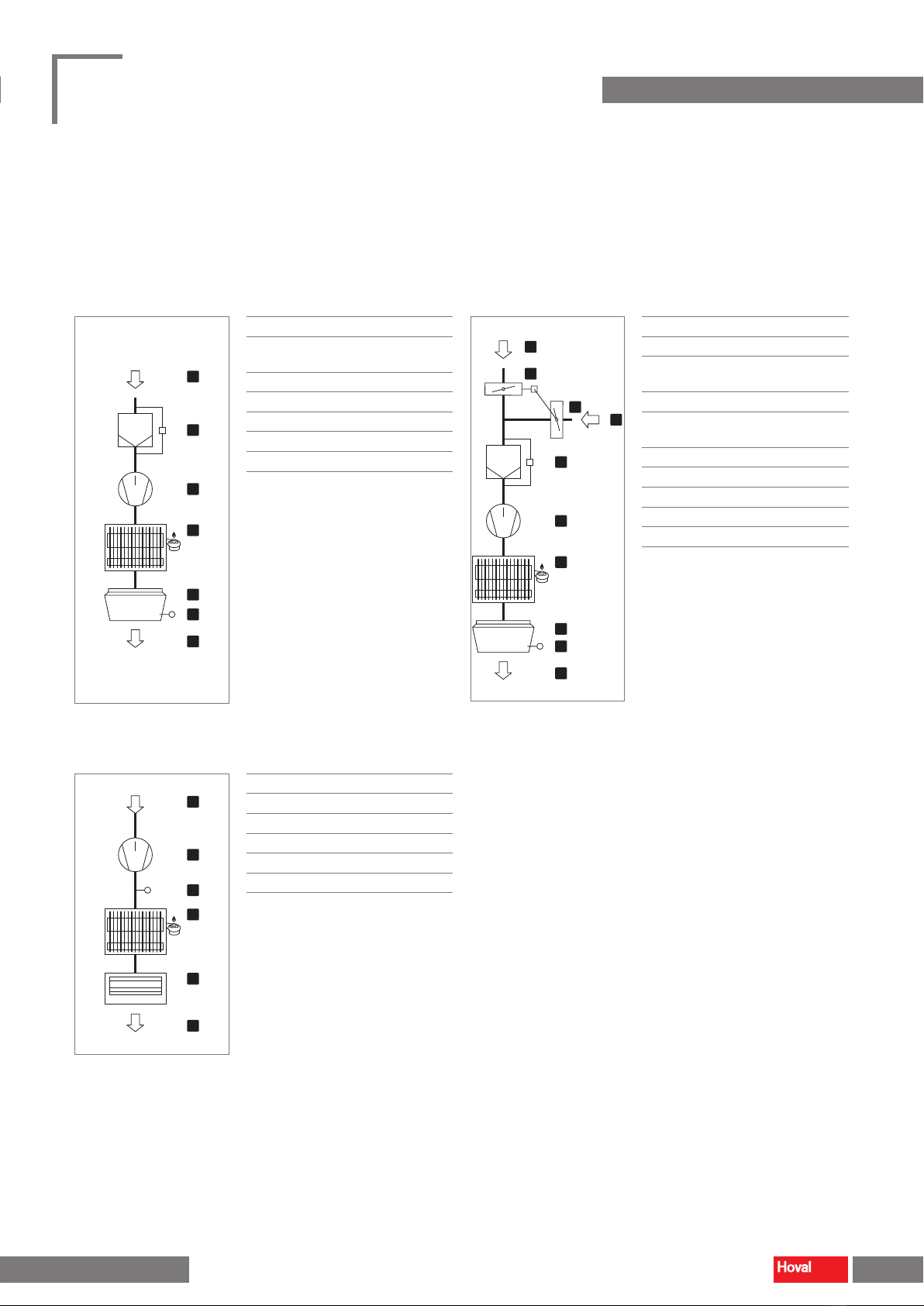
The units have the following operating modes:
■Supply air speed 2 (only TopVent® MG)
■Supply air speed 1 (only TopVent® MG)
■Recirculation
■Recirculation speed 1 (only TopVent® TG, MG)
■Standby (Night cooling only TopVent® MG)
The TopTronic® C control system regulates these operating modes automatically
for each control zone in accordance with the specications in the calendar.
The following points also apply:
■The operating mode of a control zone can be switched over manually.
■Each TopVent® unit can operate individually in a local operating mode: O,
Supply air speed 2, Supply air speed 1, Recirculation, Recirculation speed 1.
Code Operating mode Description
SA2 Supply air speed 2
The unit blows fresh air into the room. The fresh air ratio is adjustable.
The heating is regulated according to the heat demand. The room temperature set
value day is active. The unit operates at speed 2 (high air flow rate).
Fan .................................. speed 2
Fresh air damper.............. 10 % open 1)
Heating ............................ on 2)
1) Percentage is adjustable
2) Depending on heat demand
SA1 Supply air speed 1
The same as SA2, but the unit operates at speed 1 (low air flow rate)
Fan .................................. speed 1
Fresh air damper.............. 10 % open 1)
Heating ............................ on 2)
1) Percentage is adjustable
2) Depending on heat demand
REC Recirculation
On/off-operation: If heating is required, the unit draws in room air, heats it and blows
it back into the room. The room temperature set value day is active.
Fan .................................. speed 1 / 2 1)
Fresh air damper.............. closed
Heating ............................ on 1)
1) Depending on heat demand
DES ■Destratication:
To avoid heat build-up under the ceiling, it may be appropriate to switch on the fan
when there is no heat demand (either in permanent operation or in on/off opera-
tion depending on the temperature stratication, as desired).
Fan .................................. speed 2
Fresh air damper.............. closed
Heating ............................ off
REC1 Recirculation speed 1
The same as REC, but the unit operates only at speed 1
(low air flow rate)
Fan .................................. speed 1
Fresh air damper.............. closed
Heating ............................ on 1)
1) Depending on heat demand
DES ■Destratication:
The same as for REC, but the unit operates only at speed 1
Fan .................................. speed 1
Fresh air damper.............. closed
Heating ............................ off
ST Standby
The unit is ready for operation. The following operating modes are activated if
required:
CPR ■Cooling protection:
If the room temperature drops below the set value for cooling protection, the unit
heats up the room in recirculation operation.
Fan .................................. speed 2
Fresh air damper.............. closed
Heating ............................ on
8
TopVent ®TG |GV |MG
Operating instructions
Operating modes
4 220 656-en-03 4 220 656-en-03

Code Operating mode Description
NCS ■Night cooling:
If the room temperature exceeds the set value for night cooling and the current
fresh air temperature permits it, the unit blows cool fresh air into the room and
extracts warmer room air.
Fan .................................. speed 2
Fresh air damper.............. open
Heating ............................ off
L_OFF Off (local operating mode)
The unit is switched off.
Fan .................................. off
Fresh air damper.............. closed
Heating ............................ off
Table 1: Operating modes
Operating modes with TempTronic MTC
The TempTronic MTC controls the following operating modes per control zone:
Operating mode Description
Recirculation heating
The unit draws in room air, warms it and blows it back into the room.
3 setpoints can be set for regulation of the room temperature.
The controller operates in one of the following programs, as desired:
■Automatic mode with setpoint changeover according to clock programme
■Continuous operation with the room temperature setpoint day
■Continuous operation with the room temperature setpoint night
■Continuous operation with the room temperature setpoint frost
Fan .................................. modulated 1)
Heating ............................ modulated 1)
1) Depending on heat demand
Destratification
To avoid heat build-up under the ceiling, the fan can be switched on depending on the
temperature stratification. The controller compares the air temperatures in the ceiling area and in
the occupied area, and switches to destratification mode if the difference becomes too great.
Fan .................................. on
Heating ............................ off
Summer ventilation
The fan can be switched manually to 3 speeds.
Fan .................................. speed 1 / 2 / 3
Heating ............................ off
Table 2: Operating modes TopVent®GV with TempTronic MTC
8 9
TopVent ®TG |GV |MG
Operating instructions
Operating modes Operating modes
4 220 656-en-03

5 Type code
5.1 TopVent®TG
TG - 9 H / ST . D1 / S . FK . LH . UA . P / TC
Unit type TG
Unit size
6 or 9
Heating section
FCapacity 30 kW
HCapacity 60 kW
Design
ST Standard
Air outlet
D1 Design with Air-Injector
DN Outlet nozzle
Installation
-without
SSuspension set
Filter box
-- without
FK Filter box
FF Flat filter box
Paint finish
-- without
LH Standard paint finish
LU Paint finish as desired
Silencer
-- without
U- Recirculation silencer
-A Acoustic cowl
UA Recirculation silencer and acoustic cowl
Flue gas kit
-without
FFlue gas kit flat roof
PFlue gas kit pitched roof
WFlue gas kit wall
Control system
TC TopTronic®C
Table 3: TopVent®TG type code
5.2 TopVent®GV
GV - 5 G
Unit type GV
Unit size
3 or 5
Heating section
FCapacity 30 kW
GCapacity 50 kW
Table 4: TopVent®GV type code
10
TopVent ®TG |GV |MG
Operating instructions
Type code
4 220 656-en-03 4 220 656-en-03

5.3 TopVent®MG
MG - 9 H / ST . D1 / S . -- . LH . A . P / TC
Unit type MG
Unit size
6 or 9
Heating section
FCapacity 30 kW
HCapacity 60 kW
Design
ST Standard
Air outlet
D1 Design with Air-Injector
Installation
-without
SSuspension set
Paint finish
-- without
LH Standard paint finish
LU Paint finish as desired
Silencer
-without
AAcoustic cowl
Flue gas kit
-without
FFlue gas kit flat roof
PFlue gas kit pitched roof
WFlue gas kit wall
Control system
TC TopTronic®C
Table 5: TopVent®MG type code
10 11
TopVent ®TG |GV |MG
Operating instructions
Type code Type code
4 220 656-en-03

6 Technical data
6.1 Application limits
TopVent®TG, MG
Extract air temperature max. °C 50
Fresh air temperature (TopVent® MG) min. °C – 15
Supply air temperature max. °C 55
Protection rating IP 50
The units cannot be used in:
■Damp locations
■Places with a corrosive or aggressive environment
■Spaces with a large amount of dust
■Areas where there is danger of explosion
Table 6: TopVent®TG, MG application limits
TopVent®GV
Extract air temperature max. °C 50
Supply air temperature max. °C 55
The units cannot be used in:
■Damp locations
■Places with a corrosive or aggressive environment
■Spaces with a large amount of dust
■Areas where there is danger of explosion
Table 7: TopVent®GV application limits
6.2 Electrical connection
Unit type TG-6
MG-6
TG-9
MG-9 GV-3 GV-5
Supply voltage V AC 3 x 400 3 x 400 230 230
Permitted voltage tolerance %± 5 ± 5 +10 / -15 +10 / -15
Frequency Hz 50 50 50 50
Power consumption max. W1360 1960 300 750
Current consumption max. A2.3 3.4 1.4 3.5
Series fuse A13 13 16 16
Protection rating of unit control box –IP 56 IP 56 IP 00B IP 00B
Table 8: Electrical connection
6.3 Air flow rate, gas consumption
Unit type TG-6
MG-6
TG-9
MG-9 GV-3 GV-5
Nominal air flow rate 1) m³/h 6000 9000 4200 8500
Minimum air flow rate m³/h 4500 7000 2900 6000
Floor area covered m² 537 946 140 290
Nominal heat input max. kW 32.0 66.0 32.0 55.0
Nominal heat output max. kW 28.9 61.2 28.9 50.7
Gas consumption
Natural gas: G20, G27 (H, E, Lw) m³/h 3.4 7.0 3.4 5.8
Natural gas: G25, G25.3 (L, LL, K) m³/h 3.8 7.9 3.8 6.6
1) at an air temperature of 20 °C
Table 9: Technical data
12
TopVent ®TG |GV |MG
Operating instructions
Technical data
4 220 656-en-03 4 220 656-en-03

6.4 Gas connection
TopVent®TG, MG
Unit type TG-6
MG-6
TG-9
MG-9
Gas appliance type 1) B23, C13, C33 B23, C13, C33
Gas connection G ½" (internal) G ¾" (internal)
Combustion air connection DN 80 DN 80
Flue gas connection DN 80 DN 80
Max. length of flue gas duct 2) 6 m 8 m
1) according to method of flue gas evacuation and combustion air supply
2) Equivalent length of formed parts:
– 90° elbow ..... 2 m
– 45° elbow .... 1 m
– 90° T-piece ... 2 m
Table 10: TopVent®TG, MG gas circuit connections
TopVent®GV
Unit type GV-3 GV-5
Gas appliance type 1) B23, C13, C33 B23, C13, C33
Gas connection G ½" (internal) G ¾" (internal)
Combustion air connection DN 80 DN 80
Flue gas connection DN 80 DN 80
Max. length of flue gas duct 2)
Ceiling installation 2 m 2 m
Wall mounting 6 m 8 m
1) according to method of flue gas evacuation and combustion air supply
2) Equivalent length of formed parts:
– 90° elbow ..... 2 m
– 45° elbow .... 1 m
– 90° T-piece ... 2 m
Table 11: TopVent®GV gas circuit connections
6.5 Sound levels
TopVent®TG, MG
Unit type TG-6 TG-9 MG-6 MG-9
Sound pressure level
(at a dist. of 5 m) 1)
dB(A) 47 49 55 57
Total sound power level dB(A) 69 71 77 79
Octave sound power level 63 Hz dB 45 44 55 51
125 Hz dB 51 51 59 58
250 Hz dB 57 59 65 66
500 Hz dB 63 64 69 72
1000 Hz dB 66 68 74 75
2000 Hz dB 63 65 70 72
4000 Hz dB 55 58 64 66
8000 Hz dB 48 51 56 58
1) with a hemispherical radiation pattern in a low-reflection room
Table 12: TopVent®TG, MG sound power levels
TopVent®GV
Unit type GV-3 GV-5
Sound pressure level (at a distance of 5 m) 1) dB(A) 59 64
Total sound power level dB(A) 84 89
1) with a hemispherical radiation pattern in a low-reflection room
Table 13: TopVent®GV sound power levels
6.6 Heat output
Unit type TG-6
MG-6
TG-9
MG-9
GV-3 GV-5
Rated heating capacity (Prated,h)kW 28.8 61.2 28.8 50.7
Minimum capacity (Pmin)kW 17.0 37.9 17.0 31.5
Table 14: Heat output
12 13
TopVent ®TG |GV |MG
Operating instructions
Technical data Technical data
4 220 656-en-03

6.7 Dimensions and weights
TopVent®TG
Ø B
A
102
388
29
40
C
D
E
F
G
M
308
28
129
K
H
4 × M10
J
L
1
2
3
4
5
Unit type TG-6 TG-9 ■
1
Flue gas connection with measuring opening (DN 80)
■
2
Combustion air connection (DN 80)
■
3
Inspection door with measuring opening for
combustion air temperature
■
4
Gas connection (TG-6: G ½", TG-9: G ¾")
■
5
Unit control box
Amm 900 1100
Bmm 500 630
Cmm 1565 1672
Dmm 1490 1570
Emm 1000 1000
Fmm 946 1019
Gmm 836 909
Hmm 257 461
Jmm 110 110
Kmm 594 846
Lmm 89 89
Mmm 1079 1094
Weight kg 125 170
Fig. 7: TopVent®TG dimensions and weights
14
TopVent ®TG |GV |MG
Operating instructions
Technical data
4 220 656-en-03 4 220 656-en-03

TopVent®GV
GV-3 GV-5
650
495
400
11512185
652
529
264
58
753
327
131
63
92 G ½"
469
M10
M10
1
2
3
795
M10
M10
400
73546
144650
325
47090
670
170117
112
108
105 G ¾"
1
2
3
Unit type GV-3 GV-5 ■
1
Gas connection
■
2
Combustion air connection (DN 80)
■
3
Flue gas connection (DN 80)
Weight kg 40 80
Fig. 8: TopVent®GV dimensions and weights
14 15
TopVent ®TG |GV |MG
Operating instructions
Technical data Technical data
4 220 656-en-03

TopVent®MG
25
400ED
F
K
H
4 × M10
J
L
O
129
G
P
C
308
388
102
25M × N
Ø B
A
1
2
3
4
5
6
Unit type MG-6 MG-9 ■
1
Flue gas connection with measuring opening
(DN 80)
■
2
Combustion air connection (DN 80)
■
3
Inspection door with measuring opening for
combustion air temperature
■
4
Gas connection (MG-6: G ½", MG-9: G ¾")
■
5
Unit control box
■
6
Fresh air duct connection
Amm 900 1100
Bmm 500 630
Cmm 2246 2333
Dmm 490 570
Emm 1000 1000
Fmm 946 1019
Gmm 836 909
Hmm 257 461
Jmm 110 110
Kmm 797 803
Lmm 594 846
M × N mm 420 × 850 500 × 1050
Omm 89 89
Pmm 1079 1094
Weight kg 175 230
Fig. 9: TopVent®MG dimensions and weights
16
TopVent ®TG |GV |MG
Operating instructions
Technical data
4 220 656-en-03 4 220 656-en-03

7 Options
7.1 Outlet nozzle
The outlet nozzle replaces the Air-Injector. The external dimensions of the unit
remain the same. The weight is reduced:
■Size 6: – 15 kg
■Size 9: – 21 kg
The air discharge angle cannot be adjusted. Units with outlet nozzle are well-
suited for applications with lower comfort requirements and for large mounting
heights (e.g. in high-bay warehouses).
7.2 Suspension set
For ease of installation of the units, there are suspension sets available (complete
with nuts and bolts).
7.3 Air filtration
For hygiene reasons, Hoval recommends always tting TopVent®TG units with a
lter.
Filter box
A lter box with 2 bag lters can be installed for the purpose of ltering the
recirculation air. The modular construction made of aluzinc sheet metal with
2 sliding doors makes it easy to replace the lters.
A pressure dierence control device is installed for automatic monitoring of the
lter. It shows when the lters have to be changed.
Size 6 9
Amm 900 1100
Bmm 400 400
Filter class ISO coarse 60 % (G4)
Weight kg 20 24
Factory setting of differential pressure
switches Pa 120 120
Table 15: Filter box technical data
16 17
TopVent ®TG |GV |MG
Operating instructions
Technical data Options
4 220 656-en-03

Flat lter box
A at lter box with 4 pleated cell lters can be installed for the purpose of ltering
the recirculation air.
A pressure dierence control device is installed for automatic monitoring of the
lter. It shows when the lters have to be changed.
A
B
Size 6 9
Amm 900 1100
Bmm 140 165
Filter class ISO coarse 60 % (G4)
Weight kg 10 12.5
Factory setting of differential pressure
switches Pa 50 50
Table 16: Flat lter box technical data
7.4 Paint finish
If the customer wishes, the units can be provided with an exterior paint nish.
7.5 Recirculation silencer
The recirculation silencer is mounted on the appliance and thus reduces the sound
reection from the ceiling. Insertion attenuation is 3 dB compared with the total
sound power level of each TopVent® unit.
B
A
Size 6 9
Amm 900 1100
Bmm 380 485
Weight kg 15 20
Table 17: Recirculation silencer dimensions and weights
18
TopVent ®TG |GV |MG
Operating instructions
Options
4 220 656-en-03 4 220 656-en-03

7.6 Acoustic cowl
The acoustic cowl reduces the noise level in the room; it is installed in the
Air-Injector. This does not change the outside dimensions of the Air-Injector.
Insertion attenuation is 4 dB compared with the total sound power level of each
TopVent® unit.
7.7 Flue gas accessories
Flue gas kits
For simple, room air independent installation of TopVent® gas units:
Flue gas kit flat roof DN 80
Flue gas kit pitched roof DN 80
Flue gas kit wall DN 80
110
250
125
150 50
45
716
939
1850
110
250
125
150 50
45
660
865
1850
405
780
150
250
50
180
110
125
Appropriate for roof inclinations between
25° and 45°
Components:
■Roof feed-through
■Flat roof ange
■Flue gas pipe
■T-piece
■Condensate cap
■Elbow bend 90°
Components:
■Roof feed-through
■Lead pan with shell
■Flue gas pipe
■T-piece
■Condensate cap
■Elbow bend 90°
Components:
■Wall feed-through
■Flue gas pipe
■T-piece
■Condensate cap
Table 18: Flue gas kit dimensions and components (dimensions in mm)
Individual parts
For the adaptation of the ue gas kit to the particular situation:
■Flue gas pipe (250 / 500 / 1000 mm)
■Elbow (90° / 45°)
■T-piece
■Length adjustment piece
■Condensate cap
■Pipe clamp
18 19
TopVent ®TG |GV |MG
Operating instructions
Options Options
4 220 656-en-03

8 Transport and installation
Caution
Risk of injury from incorrect handling. Transport, assembly and installation
work may only be performed by specialists. Observe safety and accident
prevention regulations.
8.1 Scope of delivery
The scope of delivery includes:
■TopVent®unit
■Accessories (ue gas duct, installation material, temperature sensors)
■Optional components
1 2
■
1
TopVent®unit
■
2
Zone control panel
Fig. 10: Delivery of the components on pallets
Accessories
The following accessories are supplied separately:
■Fresh air temperature sensor and room air temperature sensor (in the zone
control panel)
■Installation material (in the Air-Injector)
■Flue gas duct
Options
The following optional components are supplied separately:
■Additional room temperature sensors (in the zone control panel)
■Zone control panel C-SYS
■Room temperature controller TempTronic MTC
Preparation
■Use a forklift with a suciently long fork to unload (at least 1.3 m).
■Check the consignment against the delivery documents and the order
conrmation to ensure that it is complete. Report missing parts and any
damage immediately in writing.
8.2 Storage
If you do not install the unit immediately:
■Remove the packaging lm to avoid water vapour condensation.
■Store the unit in a dry, dust-free room.
■Keep the storage temperature between – 30 °C and + 50 °C.
■Avoid too long storage periods. After a storage period of more than 1 year:
– Check that the bearings of the fans move smoothly before installing the unit.
20
TopVent ®TG |GV |MG
Operating instructions
Transport and installation
4 220 656-en-03 4 220 656-en-03
This manual suits for next models
2
Table of contents
Popular Ventilation Hood manuals by other brands

HYBRYD
HYBRYD ORBIT SU LED Installation and maintenance manual

Haier
Haier HHX2030 - 05-05 user manual

Inalto
Inalto ARBC90TPS quick start guide

Greenheck
Greenheck Hooded Propeller Roof Fans Installation, operating and maintenance manual

Broan
Broan BKDEG1 Installation use and care manual

Electrolux
Electrolux EFB90581OX user manual

KOBE
KOBE IN2636SQB-1 Installation instructions and operation manual

ELICA
ELICA Ciak 60 Instruction on mounting and use

Wolf
Wolf W602418 Planning information

Bertazzoni
Bertazzoni KTV24XV Installation instructions; use and care information

Bauknecht
Bauknecht DDR 5010 instructions

Trade-wind
Trade-wind 7236 Installation instructions & use & care guide