Hoymiles HRSD-2C User manual

Open Energy for All
Rapid Shutdown
HRSD-2C
HT10
HT10-Kit
USER MANUAL
Region: Global V202312 hoymiles.com

Rapid Shutdown User Manual
© 2023 Hoymiles Power Electronics Inc. All rights reserved.
Legal Notice
Hoymiles has made every eort to ensure the accuracy and completeness of this manual.
However, the content of this manual is continually reviewed and amended, due to product
enhancements or feedback from real-world usage.
Hoymiles retains the right to modify this manual without prior notice at any time. Please refer to
Hoymiles ocial website at www.hoymiles.com or scan the QR code for the latest version.
Warranty
To ensure reliability and warranty compliance, follow the installation instructions in this manual.
You can access the current warranty conditions at www.hoymiles.com.
Contact Information
If you have technical queries or any questions concerning Hoymiles products, please contact us.
Floor 6, Building 5, Housheng 99 Road, Gongshu District, Hangzhou 310015 P. R. China
hoymiles.com
Germany [email protected]
Italy [email protected]
Netherlands [email protected]
Spain [email protected]
Other EU countries [email protected]
Spanish-speaking countries [email protected]
Cannada [email protected]
Asia & Pacific [email protected]
Before contact, make sure the following information at hand:
• Model of the product
• Brief description of the problem

Rapid Shutdown User Manual
© 2023 Hoymiles Power Electronics Inc. All rights reserved.
Using This Manual
Symbols
Symbol
•List
A) ... Installation steps in a defined order
Tool and Related Documents
To quickly select HRSD or Transmitter, use Rapid Shutdown Compatibility Calculator.
For more information or related documents, refer to the product page at hoymiles.com.
Revision History
Issues
V202205 Original issue
V202310
• Added the rating in "3. Safety Instructions"
• Added "4. Cable Length and Routing"
• Updated illustrations in 5.1, 5.2, and 5.3 of "5. Installation"
• Added "6. Troubleshooting"
• Updated "7. Technical Specifications"
V202312 • Updated "7.1 HRSD-2C“

Rapid Shutdown User Manual
© 2023 Hoymiles Power Electronics Inc. All rights reserved.
CONTENTS
1. Products 01
1.1 HRSD-2C 01
1.2 HT10 02
1.3 HT10-Kit 03
2. System Overview 04
3. Safety Instructions 05
3.1 Safety Symbols 05
3.2 Safety Instructions 05
4. Cable Length and Routing 07
4.1 Conguration of Cable Lengths 07
4.2 Routing Instruction 09
5. Installation 10
5.1 HRSD-2C 10
5.2 HT10 13
5.3 HT10-Kit 16
5.4 Recommended Conduit Drilling Guide 19
6. Troubleshooting 20
6.1 Term 20
6.2 Troubleshooting Guide 20
7. Technical Specications 22
7.1 HRSD-2C 22
7.2 HT10 23
7.3 HT10-Kit 24

Rapid Shutdown User Manual
© 2023 Hoymiles Power Electronics Inc. All rights reserved. 01
1. Products
1.1 HRSD-2C
Features
• Meets SunSpec RSD, NEC 2017&NEC 2020 690.12 requirements
• Uses Active Bypass to reduce heat generation in shade and other situations
• Uses graphene heat spreader to improve heat dissipation
• Plug & play, no conguration required
• Lower power consumption and wider operating voltage range
• Able to avoid crosstalk with special communication modulation technique
As part of Hoymiles Rapid Shutdown Solution for PV system, HRSD-2C is connected with two modules.
It meets NEC 2017, NEC 2020, UL 1741 and SunSpec Rapid Shutdown requirements, guaranteeing PV
system safety.
The HRSD device enables proper operation of the PV system when it is installed and receives a “permission
to operate’‘ signal from the Hoymiles Transmitter. In an emergency, PV system would enter module-level
rapid shutdown mode by simply disconnecting the AC power of Transmitter or using an external initiator.

Rapid Shutdown User Manual
© 2023 Hoymiles Power Electronics Inc. All rights reserved. 02
1.2 HT10
Features
• Complied with NEC 2017&NEC 2020 690.12 requirements
• Complied with SunSpec RSD requirements
• Equipped with single/dual Core
• Achieves rapid shutdown through Transmitter power-o or external initiation
Hoymiles Transmitter HT10 is part of Hoymiles Rapid Shutdown Solution and works with HRSD for module-
level rapid shutdown. While powered on, the HT10 uses PLC technology to continuously send a “permission
to operate” signal to HRSD, enabling the PV system to start producing power.
In case of emergency, the PV system would enter module-level rapid shutdown mode by simply disconnecting
the AC power of Transmitter or using an external initiator.

Rapid Shutdown User Manual
© 2023 Hoymiles Power Electronics Inc. All rights reserved. 03
1.3 HT10-Kit
Features
• Module-level rapid shutdown with Hoymiles HRSD
• Achieves rapid shutdown through Transmitter power-o or external initiation
• Equipped with single/dual Core
• Complied with NEC 2017&NEC 2020 690.12 and SunSpec RSD requirements
• Weatherproof outdoor enclosure
• Equipped with single- / three-phase power supply
Hoymiles Transmitter HT10-Kit is part of Hoymiles Rapid Shutdown Solution and works with HRSD for
module-level rapid shutdown.
While powered on, the HT10-Kit uses PLC technology to continuously send a “permission to operate” signal
to HRSD, enabling the PV system to start producing power. In case of emergency, the PV system would
enter module-level rapid shutdown mode by simply disconnecting the AC power of Transmitter or using an
external initiator.
Hoymiles Transmitter Outdoor Kit includes one Transmitter, single or dual Core, single- or three-phase
power supply, and outdoor enclosure.

Rapid Shutdown User Manual
© 2023 Hoymiles Power Electronics Inc. All rights reserved. 04
2. System Overview
• The HRSD-2C requires a Transmitter or an inverter with a built-in transmitter for operation.
• Hoymiles recommends that Transmitter power supply be on the same AC branch circuit as the inverter to
meet rapid shutdown requirements.
• When power is supplied to the Transmitter, the HRSD-2C turns ON and allows full PV module voltage. The
HRSD-2C constantly receives a “permission to operate” signal from the Transmitter. When the power supply
to the Transmitter is disconnected, this “permission to operate” signal ceases, and every HRSD-2C enters
shutdown mode with output reduced to 0.9 V-1.1 V. In this way, PV array enters rapid shutdown in the event
of AC grid loss.
Inverter
Transmitter
RSD
Inverter
Transmitter
RSD
-V +V
OK
DC
PE L2 L1
DC OK

Rapid Shutdown User Manual
© 2023 Hoymiles Power Electronics Inc. All rights reserved. 05
3. Safety Instructions
3.1 Safety Symbols
This manual contains IMPORTANCE, NOTICE, WARNING, and DANGER notes. These instructions demand increas-
ingly great attention as the severity levels rise.
The instructions do not cover all the possible conditions and situations that may occur. It is important to use com-
mon sense, caution and care during installation, maintenance and operation.
3.2 Safety Instructions
Symbols Meaning
DANGER This indicates a hazardous situation that can result in high level electric shocks
and other serious physical injuries.
WARNING This indicates a hazardous situation that may result in serious physical injuries.
NOTICE This indicates a situation that can result in product damages.
IMPORTANCE This indicates complementary information.
DANGER
• No ammable and combustible material should be seen where HRSD is installed.
• Do not touch any live parts in the system, including the PV array, when the system has been connected to the electrical
grid.
• Do not connect or disconnect under load. Turning o the Inverter and/or the HRSD may not reduce the risk. Internal ca-
pacitors within the Inverter can remain charged for several minutes after all power sources are disconnected. Verify that
capacitors have discharged by measuring the voltage across inverter terminals before disconnecting wiring if service is
required. Wait 30 seconds after rapid shutdown activation before disconnecting DC cables or turning o DC disconnect.
• Do not remove the cover of the products in case of electric shock. Only professionals should carry out decommission and
repair.
WARNING
• All the installation MUST comply with local regulations and technical rules.
• Do not attempt to install in inclement weather.
• Only professionals should install and/or replace the HRSD and the Transmitter. The professionals must be qualied,
trained and skilled, and shall strictly adhere to this Manual during installation, operation and maintenance.
• The Transmitter must be powered o during HRSD installation.
• Before installing or using an HRSD or a Transmitter, please read related technical notes (see Tool and Related Docu-
ments ) and all the instructions and warnings on the inverter system itself as well as on the PV array.
• Do not operate the HRSD if it is physically damaged. Check existing cables and connectors and ensure they are in good
condition and appropriate in rating. Do not operate the HRSD with damaged or substandard wiring or connectors.
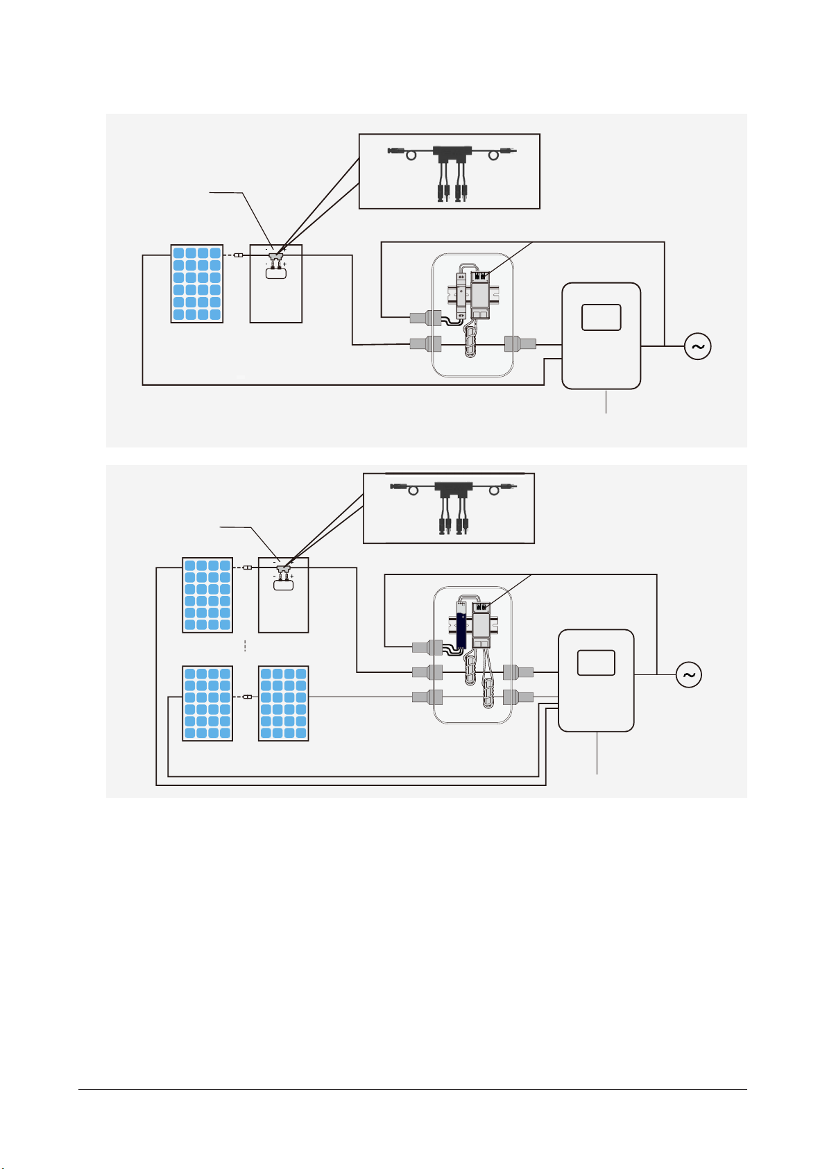
• To install the HRSD, connect the input cables to the PV module rst, and then connect the HRSD output cables in series.

Rapid Shutdown User Manual
© 2023 Hoymiles Power Electronics Inc. All rights reserved. 06
1. Source: SunSpec RapidShutdown Specication. Please refer to local regulations before installation.
2. With Φ 6 mm DC cable diameter (without DC connector) (Refer to 7.2 or 7.3 for details.)
• For parallel string connections, rst connect the HRSD to the PV modules, then connect all outputs of HRSD in series, and
nally pass one side (+ or -) of the string through the transmitter to turn the system ON.
• Do not touch the body of the running HRSD because it can reach high temperatures during heat dissipation.
• To disconnect the HRSD, remove the output cables of the HRSD string rst, and then disconnect the input cables from the
PV modules.
NOTICE
• Do not mix DC connectors from dierent manufacturers. Damages caused by it will void the Hoymiles warranty.
• Improper installation may lead to HRSD damage, which is not covered under warranty.
• Human-made damages caused by improper handling or opening the product will void the warranty.
• Be sure to verify that the voltage and current specications of the PV module match with those of the HRSD.
• Cables of the HRSD inputs and the PV module outputs cannot be extended.
• Never apply an external voltage source to a module or string equipped with HRSD.
IMPORTANCE
• To reduce the system risk, it is recommended that string inverters be able to perform Arc Fault Protection and DC
Insulation Resistance Detection during the operation.
• HRSD is shipped in the OFF position and will measure 0.9 V to 1.1 V when the “permission to operate” signal is not pres-
ent.
• Max. cable length from inverter (+) to inverter (-): 2625 ft. (800 m)
• Recommended max. number of strings connected to HRSD: 30 modules1
• Hoymiles recommends that Transmitter power supply be on the same AC branch circuit as the inverter to meet rapid
shutdown requirements.
• Max. current per Core of Transmitter: 75 A or 150 A
• Max. number of strings per Core2: 5 (75 A Core) or 15 (150 A Core)
• During the PV system operation, check that the Transmitter Power LED 1 is lit and the Signal LED 2 is blinking.
• Place rapid shutdown system label no more than 1m (3 ft.) from the Transmitter, initiator (AC disconnect) or service panel.

Rapid Shutdown User Manual
© 2023 Hoymiles Power Electronics Inc. All rights reserved. 07
4. Cable Length and Routing
4.1 Configuration of Cable Lengths
HRSDs can be mounted on both the long and short sides of the
PV module frame. Choose the suitable HRSDs
based on the installation scenario.
NOTICE
• To securely fasten the HRSD to
the PV module frame, ensure A is
15 mm at minimum for clipping.
Scenario One: Long-side Installation
For PV modules with short output cables, choose HRSDs with input cables of the suitable length shown below.
CUS
IP68 / NEMA6P
IN 1IN 2
CUS
IP68 / NEMA6P
IN 1IN 2
HRSD-2C input
cable: 1.6 m
(5.25 ft.)
PV Module output
cable: ≥0.2 m (0.66 ft.)
* The proportions of the HRSDs have been modied to improve the depiction of the structure.
For PV modules with long output cables, choose HRSDs with input cables of the suitable length shown below.
CUS
IP68 / NEMA6P
IN 1IN 2
CUS
IP68 / NEMA6P
IN 1IN 2
PV Module output
cable: ≥1.35 m (4.43 ft.)
HRSD-2C input
cable: 0.45 m
(1.48 ft.)
* The proportions of the HRSDs have been modied to improve the depiction of the structure.
AA

Rapid Shutdown User Manual
© 2023 Hoymiles Power Electronics Inc. All rights reserved. 08
Scenario Two: Short-side Installation
For PV modules with short output cables, choose HRSDs with input cables of the suitable length shown below.
CUS
IP68 / NEMA6P
IN 1IN 2
CUS
IP68 / NEMA6P
IN 1IN 2
HRSD-2C input
cable: 1.6 m
(5.25 ft.)
PV Module output
cable: ≥0.2 m (0.66 ft.)
* The proportions of the HRSDs have been modied to improve the depiction of the structure.
For PV modules with long output cables, choose HRSDs with input cables of the suitable length shown below.
CUS
IP68 / NEMA6P
IN 1IN 2
CUS
IP68 / NEMA6P
IN 1IN 2
HRSD-2C input
cable: 0.45 m
(1.48 ft.)
PV Module output
cable: ≥1.35 m (4.43 ft.)
* The proportions of the HRSDs have been modied to improve the depiction of the structure.

Rapid Shutdown User Manual
© 2023 Hoymiles Power Electronics Inc. All rights reserved. 09
4.2 Routing Instruction
To ensure eective communication,
• minimize the distance between positive and negative cables within the same string.
• up to 10 Transmitters' DC cables can pass through a single cable tray.
Number of Transmitter ≤10
String Inverter
PV arrays and HRSDs
PV modules and HRSDs
String Inverter
Minimize the
Distance
Note: This diagram only shows one
output loop’s wiring schematic in the
PV system.
PV +
PV -
PV 1 -
PV 1 +
PV 2 +
PV 2 -
Cable
Tray
Transmitter NO. 1
Transmitter NO. 10
PV 9 +
PV 10 -
PV 10 +
PV 9 -

Rapid Shutdown User Manual
© 2023 Hoymiles Power Electronics Inc. All rights reserved. 10
5. Installation
5.1 HRSD-2C
A) Buckle HRSD-2C on the PV module frame.
IMPORTANCE
• HRSD-2C output Voltage is 0.9 V to 1.1 V when Transmitter “permission to operate” signal is not
present.
• Max. cable length from inverter (+) to inverter (-): 2625 ft. (800 m)
• Max. number of strings recommended: 30 modules*
*Source: SunSpec RapidShutdown Specication. Please refer to local regulations before installation.
NOTICE
• The HRSD-2C has two inputs. If you are connecting it to one PV module, connect HRSD-2C Input 1
rst, and then short jump the HRSD-2C Input 2 - and Input 2 + together.
• Cables of the HRSD inputs and the PV module outputs cannot be extended.
NOTICE
· Maintain a minimum of 1.5 cm (0.59 inch) clearance distance
between the roof and the HRSD-2C enclosure to ensure.
ventilation and heat dissipation.
· Avoid exposing the HRSD-2C and its DC connectors to
sunlight, rain, or snow. Don’t place them between
PV modules due to potential gaps.
WARNING
• The Transmitter must be powered o during HRSD-2C installation.
• To disconnect the HRSD-2C, remove the output cables of the HRSD string rst, and then discon-
nect the input cables from the PV modules.
Mounting Brackets
IN 1IN 2
CUS
IP68 / NEMA6P
push

Rapid Shutdown User Manual
© 2023 Hoymiles Power Electronics Inc. All rights reserved. 11
B) Connect the PV modules to the HRSD-2C.

Rapid Shutdown User Manual
© 2023 Hoymiles Power Electronics Inc. All rights reserved. 12
C) Connect the outputs of HRSD-2C in series.

Rapid Shutdown User Manual
© 2023 Hoymiles Power Electronics Inc. All rights reserved. 13
5.2 HT10
A) - Mount Transmitter HT10 and power supply on DIN rail.
- Connect the Core to the Transmitter.
If there’s only one Core to connect, start with Core 1.
WARNING • Before powering on the Transmitter, ensure that the HRSD has been installed.
IMPORTANCE
• PSU and the DIN rail are not provided by Hoymiles.
• Hoymiles recommends that Transmitter power supply be on the same AC branch circuit as the in-
verter to meet rapid shutdown requirements.
• During the PV system operation, check that the Power LED 1 is lit and the Signal LED 2 is blinking.
• Place rapid shutdown system label no more than 1m (3 ft.) from the Transmitter, initiator (AC dis-
connect) or service panel.
• Max. current per Core: 75 A or 150 A
• Max. cable length from inverter (+) to inverter (-): 2625 ft. (800 m)
• Max. number of strings per Core*: 5 (75 A Core) or 15 (150 A Core)
* With Φ 6 mm DC cable diameter (without DC connector) (Refer to 7.2 or 7.3 for details.)
NOTICE • Improper installation may lead to HT10 damage, which is not covered under warranty.
INITIATOR -
Transmitter
75A Core
①Transmitter
②75 A Core
150A Core 2
Transmitter
150A Core 1
INITIATOR -
①Transmitter
②150 A Core 1
③150 A Core 2

Rapid Shutdown User Manual
© 2023 Hoymiles Power Electronics Inc. All rights reserved. 14
B) - Pass either positive homerun or negative homerun through the Core.
- Connect wires to the DC side of the power supply.
PV 1 +
PV 1 -
PV 2 +
PV 2 -
PV 1 +
PV 2 -
PV 3 -
PV 4 +
PV 1 +
PV 1 -
PV 1 +
PV 1 -
PV 2+
PV 2 -
*Either positive or negative
homerun runs through
the Core.
-
+

Rapid Shutdown User Manual
© 2023 Hoymiles Power Electronics Inc. All rights reserved. 15
C) - Connect the serially connected outputs of HRSD-2C to the inverter with a DC cable.
- Turn on AC power to Transmitter HT10 power supply to activate the “permission to operate” signal.
GRID

Rapid Shutdown User Manual
© 2023 Hoymiles Power Electronics Inc. All rights reserved. 16
5.3 HT10-Kit
A) - Mount HT10 and power supply on DIN rail.
- Connect DC leads from power supply to HT10.
- Connect the Core to the Transmitter.
If there’s only one Core to connect, start with Core 1.
WARNING
• Before powering on the Transmitter, ensure that the HRSD has been installed.
• Ground 180-550 VAC PSU with isolation class I. Grounding is not necessary for an 85-264 VAC PSU
with isolation class II.
IMPORTANCE
• Hoymiles recommends that Transmitter power supply be on the same AC branch circuit as the in-
verter to meet rapid shutdown requirements.
• During the PV system operation, check that the Power LED 1 is lit and the Signal LED 2 is blinking.
• Place rapid shutdown system label no more than 1m (3ft) from the Transmitter, initiator (AC discon-
nect) or service panel.
• Max. current per Core: 75 A or 150 A
• Max. cable length from inverter (+) to inverter (-): 2625 ft. (800 m)
• Max. number of strings per Core*: 5 (75 A Core) or 15 (150 A Core)
* With Φ 6 mm DC cable diameter (without DC connector) (Refer to 7.2 or 7.3 for details.)
NOTICE • Improper installation may lead to HT10-Kit damage, which is not covered under warranty.
INITIATOR -
L
N
GND
+12 V
①Transmitter
② 85-264 VAC
DIN Rail PSU
③75 A Core
INITIATOR -
+12 V
GND
INITIATOR
+
LED 1
CORE
2
LED 2
LED 2
CORE
1
-V +V
OK
DC
PE L2 L1
DC OK
+V
PE
L2
L1
-V
① Transmitter
② 180-550 VAC
DIN Rail PSU
③150 A Core 1
④150 A Core 2
Other manuals for HRSD-2C
1
This manual suits for next models
2
Table of contents
Other Hoymiles Cables And Connectors manuals