manuals.online logo
Brands
  1. Home
  2. •
  3. Brands
  4. •
  5. LEGRAND
  6. •
  7. Cables And Connectors
  8. •
  9. LEGRAND AV3STC User manual

LEGRAND AV3STC User manual

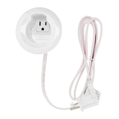
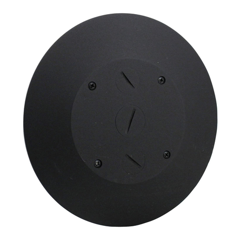
Products Covered: AV3STC, 4FFATC, 4FFCTC
CAUTION DO NOT operate tile stripper or resurfacing equipment over top of covers. This may result in damage to the
surface finish of the product.
Suitable for use in air handling spaces in accordance with Sec. 300-22 (C) of the National Electrical Code.
4" Furniture Feed Poke-Thru Device
INSTALLATION INSTRUCTIONS
Installation Instruction No.: 1 004 301 – January 2005
Walker® electrical systems conform to and should be properly grounded
in compliance with requirements of the current National Electrical Code
or codes administered by local authorities.
All electrical products may present a possible shock or fire hazard if
improperly installed or used. Walker electrical products may bear the
mark as UL Listed and/or Classified and should be installed in
conformance with current local and/or the National Electrical Code.
24" [610mm] Min
Center – Center
7"
[178mm]
CAUTION: Be certain to drill hole at least 4" [102mm] from any wall or
pillar to leave enough room for Poke-Thru cover assembly.
CAUTION: For tile installations up to a maximum of
3/4" [19.1mm] thick.
NOTE: For tile thickness greater than 3/4" [19.1mm]
consult factory.
IMPORTANT: Please read all instructions
before beginning.
CAUTION: Spacing is limited to 2 feet on center and no
more than one hole per each 65 sq. ft. [6 sq. m]
of floor area in each span.
Step 2 Remove 7" dia. [178mm] section from carpet
or tile. Use template provided.
Step 1 Layout and locate position of hole(s).
Step 3 Core drill hole.
CAUTION: Poke-Thru cannot be rotated in
hole after inserted into floor.
4" [102mm] Diameter Core Drill
4 1/16" [103mm] Actual Diameter
Push Down
#6-32 x 3/8" PHMS
three (3) required
Step 4 Stem Assembly:
Catalog No. AV3STC
Insert stem into hole.
Step 5 Cover Assembly:
Catalog No. 4FFCTC.
Remove disposable plate
and replace with carpet/tile
flange. Install with three (3)
#6-32 x 3/8" [9.5mm] PHMS.
2
Push
Down
Step 6 Complete assembly: Catalog No. 4FFTATC Step 7 With the assembly installed, remove the
screw plugs and install conduit fittings as
necessary. Attach conduit to adapter.
CAUTION: Poke-Thru cannot be rotated in
hole after inserted into floor.
Step 8 Pull cables and complete installation.
1 1/4" Trade Size Flexible
EMT. Not required
For Communication
Conduit Fitting.
3/4" Trade Size Flexible
EMT. Must Be Attached
To Power Conduit Fitting.
The 4FFTC Series Poke-Thru Devices are UL Listed and Classified to U.S. and Canadian safety
standards to the following conditions:
The AV3STC poke-thru stem with the 4FFCTC service head fitting, the 4FFATC factory assembled poke-thru device are for use with
1, 1-1/2, and 2 hr rated unprotected reinforced concrete floors and 1, 1-1/2 or 2 hr rated floors employing unprotected steel floor
units and concrete topping (D900-Series Designs), or concrete floors with suspended ceilings. (Fire resistive designs with suspended
ceilings should have provisions for accessibility in the ceiling area below the poke-thru fittings).
The assembled poke-thru stem and service fitting will not reduce the ratings of the floor assembly when the thickness and type of
concrete(required for the specific rating) are within the specified limits and the fittings are installed as specified:
1. – Spacing – Minimum of 2' [610mm] OC and not more than one unit per 65 sq ft [6 sq. m] of floor area in each span.
2. – Concrete – Minimum thickness of structural concrete topping of 2 1/4 in. [57mm] over metal deck or a minimum
3 in. thick reinforced concrete slab. Unit weight of concrete to be 110 to 155 pcf.
3. – Installation – Mounted in a 4 in. diameter core-drilled hole in concrete per installation instructions accompanying the
fittings or abandonment fittings. For use with power circuits, date and/or telephone cables as tabulated below:
The “TC” suffix letters indicate that device may be installed on tile or carpet covered concrete floors. The “LJB” suffix letters
indicate units supplied without a junction box.
(A) Maximum number of No. 12 AWG Type THHN conductors in power compartment of Poke-Thru fitting.
(B) Maximum number of 22 AWG conductors in low-voltage compartment of Poke-Thru fitting (4 pair cables have
8 conductors). When conductors larger than No. 22 AWG are used, the aggregate cross-sectional area of
the copper conductors shall not exceed the aggregate cross-sectional area of the 22 AWG conductors
permitted in the low-voltage compartment.
FLOOR COVERINGS: The poke-thru device is fire rated for carpet or wood covered floors, tile floor coverings up to 3/4" [19.1 mm]
maximum thickness, and linoleum floor coverings up to a maximum 1/8" [3.2 mm] thickness. For other floor coverings not listed
above, consult factory.
Size Solid
#24 .00032 sq. in. [.20645mm2]
#22 .00050 sq. in. [.32258mm2]
#14 .00323 sq. in. [2.08386mm2]
#12 .00512 sq. in. [3.30321mm2]
#10 .00815 sq. in. [5.25805mm2]
# 8 .01296 sq. in. [8.36127mm2]
COPPER CROSS SECTIONAL AREA
OF COMMONLY USED CONDUCTORS
NOTE: Use above values for solid or stranded conductors.
3
4FFATC Series – 16 (.08192 sq in.) [52.861mm2]144
(.072 sq. in.) [46.452mm2]
AV3STC Series 4FFCTC Series 16 (.08192 sq in.) [52.861mm2]144
(.072 sq. in.) [46.452mm2]
POKE-THRU SERVICE POWER COMMUNICATION
FITTING TYPE FITTING TYPE CONDUCTORS (A) CONDUCTORS (B)
The Wiremold Company
U.S. and International:
60 Woodlawn Street • West Hartford, CT 06110
1-800-621-0049 • FAX 860-232-2062 • Outside U.S.: 860-233-6251
Canada:
850 Gartshore Street • Fergus, Ontario N1M 2W8
1-800-741-7957 • FAX 519-843-5980
1 004 301 0105
© Copyright 2005 The Wiremold Company All Rights Reserved
Carpet Cutout
7" [178mm]
Core Hole
4 1/16" [103mm]
CAUTION: When printing copies of
this template please be
sure template is scaled
correctly and is the
correct size once it
is printed.
Carpet Cutout Template

This manual suits for next models

2

Other LEGRAND Cables And Connectors manuals

LEGRAND Wiremold 2000TRGFI User manual

LEGRAND

LEGRAND Wiremold 2000TRGFI User manual

LEGRAND SPX 00 User manual

LEGRAND

LEGRAND SPX 00 User manual

LEGRAND RC7FF Poke-Thru Series User manual

LEGRAND

LEGRAND RC7FF Poke-Thru Series User manual

LEGRAND LCS 0 337 53 User manual

LEGRAND

LEGRAND LCS 0 337 53 User manual

LEGRAND Pass & Seymour 1597PC User manual

LEGRAND

LEGRAND Pass & Seymour 1597PC User manual

LEGRAND Niloe 6 645 73 User manual

LEGRAND

LEGRAND Niloe 6 645 73 User manual

LEGRAND 673 17/787 68 User manual

LEGRAND

LEGRAND 673 17/787 68 User manual

LEGRAND WIREMOLD MDSF User manual

LEGRAND

LEGRAND WIREMOLD MDSF User manual

LEGRAND 4 130 39 User manual

LEGRAND

LEGRAND 4 130 39 User manual

LEGRAND Wiremold Walkerflex FCA User manual

LEGRAND

LEGRAND Wiremold Walkerflex FCA User manual

LEGRAND Linkeo C User manual

LEGRAND

LEGRAND Linkeo C User manual

LEGRAND 025626 User manual

LEGRAND

LEGRAND 025626 User manual

LEGRAND WIREMOLD XEVCABLE User manual

LEGRAND

LEGRAND WIREMOLD XEVCABLE User manual

LEGRAND EZ-RJ AC3450-50 User manual

LEGRAND

LEGRAND EZ-RJ AC3450-50 User manual

LEGRAND 33250 User manual

LEGRAND

LEGRAND 33250 User manual

LEGRAND ON-Q HT2302B User manual

LEGRAND

LEGRAND ON-Q HT2302B User manual

LEGRAND Cablofil User manual

LEGRAND

LEGRAND Cablofil User manual

LEGRAND LE-50444 User manual

LEGRAND

LEGRAND LE-50444 User manual

LEGRAND 0 648 47 User manual

LEGRAND

LEGRAND 0 648 47 User manual

LEGRAND RJ 11 User manual

LEGRAND

LEGRAND RJ 11 User manual

LEGRAND 330 48 User manual

LEGRAND

LEGRAND 330 48 User manual

LEGRAND 882 02 User manual

LEGRAND

LEGRAND 882 02 User manual

LEGRAND WIREMOLD CMK70 User manual

LEGRAND

LEGRAND WIREMOLD CMK70 User manual

LEGRAND WIREMOLD MDSA User manual

LEGRAND

LEGRAND WIREMOLD MDSA User manual

Popular Cables And Connectors manuals by other brands

Gefen EXT-HDMI1.3-142D user manual

Gefen

Gefen EXT-HDMI1.3-142D user manual

Philips SWV3523 Specifications

Philips

Philips SWV3523 Specifications

TRENDnet TPE-114GS Specifications

TRENDnet

TRENDnet TPE-114GS Specifications

SMC Networks DM Series manual

SMC Networks

SMC Networks DM Series manual

Eaton EU4A-RJ45-CAB2 Instruction leaflet

Eaton

Eaton EU4A-RJ45-CAB2 Instruction leaflet

Harbor Freight Tools THUNDERBOLT SOLAR 59171 Owner's manual & safety instructions

Harbor Freight Tools

Harbor Freight Tools THUNDERBOLT SOLAR 59171 Owner's manual & safety instructions

PASCO ME-1242 instruction manual

PASCO

PASCO ME-1242 instruction manual

Sirius Satellite Radio SR-100C installation guide

Sirius Satellite Radio

Sirius Satellite Radio SR-100C installation guide

NEUTRIK PowerCon NAC3MPA operating instructions

NEUTRIK

NEUTRIK PowerCon NAC3MPA operating instructions

Tektronix Keithley 2657A-PCT-KIT manual

Tektronix

Tektronix Keithley 2657A-PCT-KIT manual

KStrong FC409151 User instruction manual

KStrong

KStrong FC409151 User instruction manual

Cypress CHDMI-210T Operation manual

Cypress

Cypress CHDMI-210T Operation manual

Comprehensive CDA-HD200EK Operation manual

Comprehensive

Comprehensive CDA-HD200EK Operation manual

Xantech MRCKPSP installation instructions

Xantech

Xantech MRCKPSP installation instructions

Scion-Tech SC02.0104 operating instructions

Scion-Tech

Scion-Tech SC02.0104 operating instructions

Motorola NKN6498 manual

Motorola

Motorola NKN6498 manual

TechLogix Networx TL-DA14-F2 user manual

TechLogix Networx

TechLogix Networx TL-DA14-F2 user manual

Parker Phastite PH-4-PS installation manual

Parker

Parker Phastite PH-4-PS installation manual

manuals.online logo
manuals.online logoBrands
  • About & Mission
  • Contact us
  • Privacy Policy
  • Terms and Conditions

Copyright 2025 Manuals.Online. All Rights Reserved.