Eltroplan REVCON RHD Series User manual

ELTROPLAN-REVCON
Elektrotechnische Anlagen GmbH
Operating instructions
Power feedback unit REVCON
RHD
Power range 4 ... 400 kW
Voltage range 230V, 400V, 460V,
500V, 690V
V 1.2 Issue 05/13

Contents
Operating instructions RHD 1
ELTROPLAN - REVCON
Elektrotechnische Anlagen GmbH
1 Preface and general information ............................................................................................ 3
1.1 About these Operating Instructions ....................................................................................... 3
1.1.1 Terminology used .................................................................................................................. 3
1.1.2 Ordering code ....................................................................................................................... 4
1.1.3 cope of delivery ................................................................................................................... 4
1.1.4 Product selection ................................................................................................................... 5
1.1.5 Legal regulations ................................................................................................................... 6
2 EC-Directives / Declaration of conformity ............................................................................... 7
2.1 EC-Low-Voltage Directive ....................................................................................................... 7
2.2 EC-directive Electromagnetic compatibility ............................................................................ 8
2.3 EC-directive Machinery .......................................................................................................... 9
3 afety information .............................................................................................................. 10
3.1 General safety information .................................................................................................. 11
3.2 afety-responsible persons .................................................................................................. 15
3.3 Layout of the safety information .......................................................................................... 16
3.4 Residual hazards .................................................................................................................. 16
3.5 General instructions ............................................................................................................ 17
4 Technical data ..................................................................................................................... 28
4.1 Characteristics ..................................................................................................................... 28
4.2 General data/ application conditions ................................................................................... 29
4.3 Rated data .......................................................................................................................... 30
4.3.1 Power feedback unit RHD B0/D0 .......................................................................................... 30
5 Current load ........................................................................................................................ 31
5.1 Current load REVCON RHD B0/D0 ........................................................................................ 31
5.2 Fuses and wire cross sections ............................................................................................... 34
5.2.1 eries fuses RHD B0/D0 ..................................................................................................... 34
5.3 Internal fuses ...................................................................................................................... 36
5.3.1 Internal fuses RHD B0/D0 .................................................................................................. 36
5.4 RFI-filter .............................................................................................................................. 39
5.4.1 RFI-filter RLD-B0/D0 .......................................................................................................... 39
5.5 Harmonic filter module RHF-RA ........................................................................................... 41
5.5.1 RHF-RA filter RHD-B0/D0 ................................................................................................... 41
6 Installation .......................................................................................................................... 43
6.1 Dimensions REVCON RHD .................................................................................................... 44

Contents
2 Operating instructions RHD
ELTROPLAN - REVCON
Elektrotechnische Anlagen GmbH
6.2 RFI-filter .............................................................................................................................. 49
6.3 RHF-RA-filter ....................................................................................................................... 52
7 Electrical Installation ........................................................................................................... 57
7.1 Mains types / Mains characteristics ..................................................................................... 58
7.2 Connection .......................................................................................................................... 59
7.3 Power connection................................................................................................................ 59
7.3.1 Wiring schematic RHD B0/D0 ............................................................................................... 61
7.3.2 Wiring schematic RHD B0/D0 and FC with RHF-RA ................................................................ 63
7.3.3 Wiring schematic RHD B0/D0 with RHF-RA ........................................................................... 65
7.4 Fan supply ........................................................................................................................... 67
7.5 Control wires ....................................................................................................................... 67
7.6 Control functions ................................................................................................................. 67
7.7 Application example ............................................................................................................ 71
7.8 Installation of a power feedback unit in a CE-typical drive system ......................................... 72
8 Installation .......................................................................................................................... 74
8.1 Connection of a RFI-filter ..................................................................................................... 75
8.2 Design of an EMC-conformal cabinet .................................................................................... 76
8.3 Remarks .............................................................................................................................. 77
8.4 Installation of control wires ................................................................................................. 78
9 Commissioning .................................................................................................................... 79
9.1 First powering up ................................................................................................................ 79
10 Configuration ...................................................................................................................... 80
11 Troubleshooting and fault elimination ................................................................................. 83
11.1 LED-messages ...................................................................................................................... 84
12 ervice ................................................................................................................................ 86
13 Appendix ............................................................................................................................. 87
13.1 Options ............................................................................................................................... 87
14 REVCON
®
Product overview ................................................................................................. 89
15 Contact ............................................................................................................................... 90

Preface and general information
Operating instructions RHD 3
ELTROPLAN - REVCON
Elektrotechnische Anlagen GmbH
1Preface and general information
1.1 About these Operating Instructions
•These Operating Instructions help you to work properly on and with the power feed-
back units REVCON
RHD. They contain safety information which must be observed
and information which are necessary for an undisturbed operation of the units together
with the exploitation of all the advantages of the system.
•All persons who work on and with the power feedback units REVCON
RHD must
have the Operation instructions available and observe all relevant notes and instruc-
tion.
•The Operating Instructions must always be in a complete and perfectly readable state.
1.1.1 Terminology used
Power feedback unit
For „Power feedback unit
„
REVCON
RHD“ in the following the term „Power feedback
unit“ is used.
Controller
For the frequency inverter which is used together with the power feedback unit in the fol-
lowing the term „Controller“ is used.
Drive system
For a drive system with power feedback units, controller and other components of the drive
system in the following the term „Drive system“ is used.

Preface and general information
4 Operating instructions RHD
ELTROPLAN - REVCON
Elektrotechnische Anlagen GmbH
1.1.2 Ordering code
1.1.3 Scope of delivery
•1 Power feedback unit REVCON
RHD
•1 Operating instructions
•After receipt of the delivery verify immediately, if the scope of supply correspond
to the shipping documents. We make no warranty for later complained defects
Claim
•Visible transport damages in transit immediately at the deliverer.
•Visible deficiencies/incompleteness immediately to ELTROPLAN-REVCON.
R
H
D
B0
033
-
400
-
50
-
0
-
A
B
•
Level B:
ith internal mains inductance
033
• Nominal feedback
power: e.g. 33k
50
•
Mains frequency:
e.g. 50Hz
A
•
Version: A
RLD
•Product type:
REVCON- High Duty
For up to 100% duty
cycle
0
400
•
Connection voltage:
e.g. 400VAC
0
•
Auxiliary voltage
:
0=Not required
•
0: ithout integrated
harmonic filter
400V
1:
ith integrated
harmonic filter
•
Level D: ith internal mains inductance
and additional DC capacity
•

Preface and general information
Operating instructions RHD 5
ELTROPLAN - REVCON
Elektrotechnische Anlagen GmbH
1.1.4 Product selection
Selection
REVCON RHD B or D:
→REVCON Type RHD B is sufficient for drives with direct DC-Bus connection.
→REVCON Type RLD D is required for drives with DC-Bus connection.via the DC-
choke(s). This unit contains additional capacity to compensate the magnetic energy from
the DC choke in case of a system shutdown.
Preface and general information
6 Operating instructions RHD
ELTROPLAN - REVCON
Elektrotechnische Anlagen GmbH
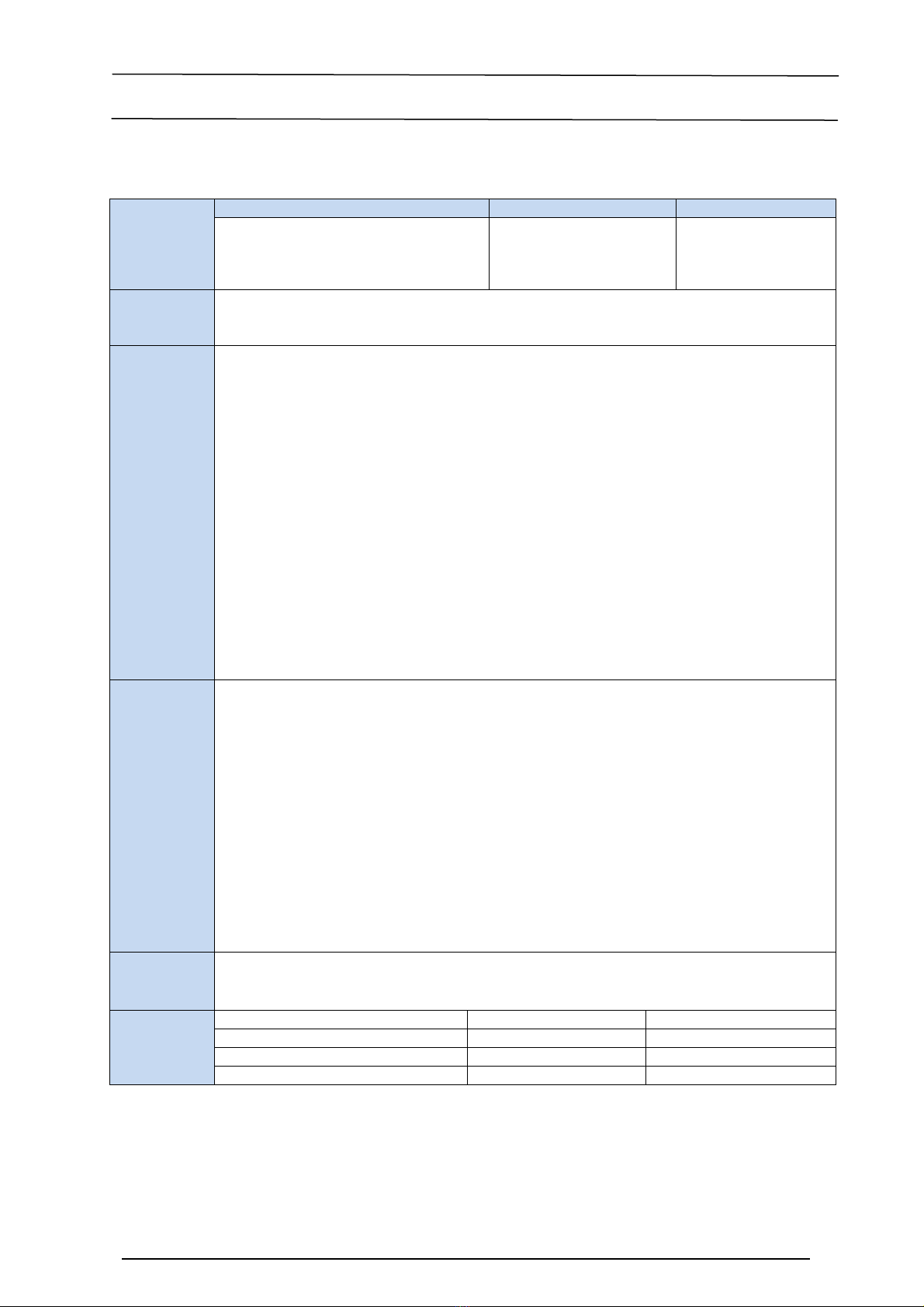
1.1.5 Legal regulations
Labelling Nameplate CE-mark Manufacturer
Power feedback units REVCON
RHD
are unequivocally marked by the contents
of the nameplate.
Conforms the EC Low
Voltage Directive
ELTROPLAN-
REVCON
Edisonstraße 3
D-59199 Bönen
Patent rights The power feedback unit REVCON
is protected in Germany and Europe by patents:
Patent-No.: DE 3938654C1 and Patent-Nr.: 90123584.6-2207.
Patent infringements become prosecute.
Application
as directed
Power feedback unit REVCON
RHD
•Must only be operated under the conditions prescribed in these instructions.
•Are components
– to feedback electrical energy
– used for installation into a machine
– used for assembly together with other components to from a machine
•Are electric units for the installation into control cabinets or similar enclosed operating
housing.
•Comply with the requirements of the Low-Voltage Directive
•Are not machines for the purpose of the Machinery Directive
•Are not to be used as domestic appliances, but only for industrial purpose.
Drive systems with power feedback unit REVCON
RHD
•Comply with the EMC-Directive if they are installed according to the guidelines of CE-typical
drive systems.
•Can be used
– on public and non-public mains
– in industrial as well as residential and commercial premises
•The user is responsible for the compliance of this application with the EC directives.
Liability
•
The information, data and notes in these Operating Instructions met the state of the art at the
time of printing. Claims referring to power feedback units which have already been supplied
cannot be derived from information, illustrations and descriptions given in these Operation In-
structions.
•The specifications, processes and circuitry described in these Operating Instructions are for
guidance only and must be adapted to your own specific application. ELTROPLAN-REVCON
does not take responsibility for the suitability of the process and circuit proposals.
•The indications given in these Operating Instructions describe the features of the product with-
out warranting them.
•ELTROPLAN-REVCON does not accept any liability for damage and operating interference
caused by:
– disregarding these instructions
– unauthorized modifications to the power feedback unit
– operating errors
– improper working on and with the power feedback unit
Warranty
•
Warranty conditions: see sales and delivery conditions of ELTROPLAN-REVCON GmbH.
•Warranty claims must be made immediately after detecting defects or faults.
•The warranty is void in all cases where liability claims cannot be made.
Disposal Material recycle disposal
Metal -
Plastic -
Printed-board assemblies -

Preface and general information
Operating instructions RHD 7
ELTROPLAN - REVCON
Elektrotechnische Anlagen GmbH
2EC-Directives / Declaration of conformity
What is the purpose of EC-Directives?
The EC-Directives have been drawn up by the European council to define common techni-
cal standards and certification procedures within the European Community. At the moment
there are 21 EC-Directives for product sectors. The directives are or will be converted in
national laws by the member states. If a certificate is conferred in one member state, it is
valid in all other member states automatically.
The directives only describe the basic standards. The technical details are or will be de-
scribed in harmonized European standards.
What is the meaning of the CE-marking?
After a conformity-assessment-procedure the conformity with the standards of the EC-
Directives is certified by fixing the CE-marking. Within the EC there are no trading obsta-
cles for a CE-marked product.
Power feedback units with CE-marking themselves are compliant with the Low-Voltage
Directive only
.
For observing the EMC Directive recommendations are made.
2.1 EC-Low-Voltage Directive
(73/23/EEC)
Modified by: CE – Marking Directive (93/68/EEC)
CE – Marking Directive (2006/95/EEC)
General:
•The Low-Voltage Directive is valid for all electrical equipment which is used at a nominal
voltage between 50V and 1000V AC and between 75V and 1500V DC together with cus-
tomary environment conditions. Excluded is e.g. the use of electrical equipment in explo-
sive areas and electrical components of lifts for persons or material.
•Aim of the Low-Voltage Directive is to put only those products into commerce which
don’t endanger the safety of persons and animals as well as the preservation of material as-
sets.

Preface and general information
8 Operating instructions RHD
ELTROPLAN - REVCON
Elektrotechnische Anlagen GmbH
EC-declaration of conformity
According to the EC-Low Voltage Directive (2006/95/EEC)
The power feedback units REVCON
RHD have been developed, designed and manu-
factured in accordance with the above mentioned EC-Directive and in sole responsibil-
ity of
ELTROPLAN-REVCON Elektrotechnische Anlagen GmbH,
Edisonstraße 3, D-59199 Bönen
Considered standards:
Standard
DIN VDE 0160 5.88 +A1 / 4.89 +A2 / 10.88
PRDIN EN 50178
Class VDE 0160 / 11.94
Equipment of power installations with
electronic components
EN 61558-1/A1 Safety of power transformers, power supplies,
reactors and similar products
EN 60529 International protection rating
DIN VDE 0100 Guidelines for the design of
power installations
2.2 EC-directive Electromagnetic compatibility
EMC directive (89/336/EWG)
Replaced by: EMC-directive (2004/108/EG)
General:
The objective target describes article 4 (2004/108/EG), as follows:
The... designated devices must be so manufactured, that
(a) an intended operation of radio- and telecommunication devices and other devices is
possible and
(b) the devices have an adequate stability against electromagnetically disturbances, so
that an intended operation is possible.

Preface and general information
Operating instructions RHD 9
ELTROPLAN - REVCON
Elektrotechnische Anlagen GmbH
EG-declaration by the manufacturer
in terms of the EG-standard EMC (2004/108/EG)
The listed REVCON
products are in terms of the EMC no independently recoverable
products, this means only after integration in the overall system would they be rateable
regarding to EMC. The rating became detected for typical plant constructions, but not for
the several products.
ELTROPLAN- REVCON Elektrotechnische Anlagen GmbH,
Edisonstraße 3, D-59199 Bönen
Considered standards:
Standard
DIN EN 61000-3-3:2008
(IEC 61000-3-3:2008)
Generic standards Limits: Limitation of voltage changes, voltage fluctua-
tions and flicker in public low-voltage supply systems
DIN EN 61000-6-2:2005
(IEC 61000-6-2:2005)
Generic standards - Immunity for industrial environments
DIN EN 61000-6-3:2007 +A1:2011
(IEC 61000-6-3:2006+A1:2010)
Generic standards - Emission standard for residential, commercial and
light-industrial environments
DIN EN 61000-6-4:2007 + A1:2011
(IEC 61000-6-4:2006+A1:2010)
Generic standards - Emission standard for industrial environments
2.3 EC-directive Machinery
Machine directive (98/37/EG)
Changed by: Modification directive (2006/42/EG)
General:
Machinery means an assembly, fitted with or intended to be fitted with a drive system
other than directly applied human or animal effort, consisting of linked parts or compo-
nents, at least one of which moves, and which are joined together for a specific applica-
tion.
EC- declaration by the manufacturer
in terms of the EG-directive machines (2006/42/EG)
The Energy feedback units REVCON
RHD were developed, designed and manufac-
tured in accordance to the above named EG- directive in exclusive accountability by
ELTROPLAN-REVCON
Elektrotechnische Anlagen GmbH,
Edisonstraße 3, D-59199 Bönen
The operation of the Energy feedback units REVCON
RHD is prohibited as long as it is
determined, that the machine, in which it should be installed, conforms to the regulations
of the EG-directive machines.

afety information
10 Operating instructions RHD
ELTROPLAN - REVCON
Elektrotechnische Anlagen GmbH
3Safety information
Safety and application notes
for drive converters
(Low-Voltage Directive (2006/95/EEC)
1.
General
During operation, power feedback unit may have, according to their
type of protection, live, bare, in some cases also movable or rotating
parts as well as hot surfaces.
Non –authorized removal of required cover, inappropriate use, incor-
rect installation or operation, creates the risk of severe injury to per-
sons or damage to material assets.
Further information can be obtained from the documentation.
All operations concerning transport, installation and commissioning as
well as maintenance must be carried out by qualified, skilled person-
nel (IEC 364 and CENELEC HD 384 or DIN VDE 0100 and IEC-
Report 664 or DIN VDE 0110 and national regulations for the preven-
tions of accidents must be observed).
According to this basic safety information qualified skilled personnel
are persons who are familiar with the erection, assembly, commission-
ing and operation of the product and who have the qualifications nec-
essary for their occupation .
2.
Application as directed
Power feedback units are components which are designed for installa-
tion in electrical systems or machinery.
When installing in machines, commissioning of the power feedback
unit (i.e. the starting of operation as directed) is prohibited until it is
proven, that the machine corresponds to the regulations of the EC Di-
rective (2006/42/EG) (Machinery Directive); EN 60204 must be ob-
served.
Commissioning (i.e. starting operation as directed) is only allowed
when there is compliance with the EMC-Directive (2004/108/EG).
The power feedback units meet the requirements of the Low-Voltage
Directive (2006/95/EEC). The harmonized standards of the prEN
50178/DIN VDE 0160 series together with EN 60439-1/DIN VDE
0660 part 500 and EN 60146/DIN VDE 0558 are applicable for the
power feedback unit. The technical data and information on the con-
nection conditions must be obtained from the nameplate and the
documentation and must be observed in all cases.
3.
Transport, Storage
Notes on transport, storage and appropriate handling must be observed
At non-observance any warranty expires.
The power feedback unit has to be protected from inadmissible stress.
The transport is only valid in original packaging and in the thereon by
pictograms marked transport position.
In particular during transport and handling no components are allowed
to be bent and / or isolating distances may not be altered. The units are
equipped with electrostatic sensitive devices, which may be damaged
by improper handling. Therefore it has to be avoided to get in contact
with electronic components. If electronic components are damaged
mechanically the unit must not be put into operation, as it cannot be
ensured, that all relevant standards are observed. Climatic conditions
must be observed according to prEN 50178.
4.
Erection
The devices must be erected and cooled according to the regu-
lations of the corresponding documentation.
The power feedback units must be protected from inappropriate
loads. Particularly during transport and handling, components
must not be bent and / or isolating distances must not be
changed. Touching of electronic components and contacts must
be avoided.
Power feedback units contain electro-statically sensitive com-
ponents which can easily be damaged by inappropriate han-
dling. Electrical components must not be damaged or destroyed
mechanically (health risk are possible!).
5.
Electrical Connection
When working on live power feedback units, the valid national
regulations for the prevention of accidents (e.g. VBG 4) must
be observed. Before any installation or connection works, the
plant has to be switched off and to be secured properly.
The electrical installation must be carried out according to the
appropriate regulations (e.g. cable cross-sections, fuses, PE-
connection). More detailed information is included in the
documentation. When using the power feedback unit with con-
trollers without safe separation from the supply line (to VDE
0100) all control wiring has to be include in further protective
measures (e.g. double insulated or shielded, grounded and insu-
lated).
Notes concerning the installation in compliance with EMC –
such as screening, grounding, arrangement of filters and lying
of cables – are included in the chapter installation of this docu-
mentation. These notes must be also observed in all cases for
power feedback units with the CE-mark. The compliance with
the required limit values demanded by the EMC legislation is
the responsibility of the manufacturer of the system or machine.
6.
Operation
Systems where power feedback units are installed, if applicable,
have to be equipped with additional monitoring and protective
devices according to the valid safety regulations e.g. law on
technical tools, regulations for the prevention of accidents, etc. .
After disconnecting the power feedback unit from the supply
voltage, live parts of the power feedback unit and power con-
nections must not be touched immediately, because of possibly
charged capacitors. For this, observe the corresponding labels
on the drive controllers.
During operation, all covers and doors must be closed.
7.
Maintenance and service
The manufacturer’s documentation must be observed.
This safety information must be kept!
The product-specific safety and application notes in these Op-
erating Instructions must also be observed!

afety information
Operating instructions RHD 11
ELTROPLAN - REVCON
Elektrotechnische Anlagen GmbH
3.1 General safety information
•These safety regulations are not entitled to completeness. In case of questions please
contact our technicians.
•When commissioning the power feedback units are compliant with the state of the
art. The power feedback unit generally allows safe operation.
•The statements of this manual describe the attributes of the products without guaran-
teeing them.
•The power feedback unit may expose persons, the power feedback units itself and
other material to danger, if
– non qualified personal works at and with the power feedback unit.
– The power feedback unit is used in opposite to its purpose.
•Power feedback units have to be projected in a way, that they fulfil their function and
don’t expose persons to danger, if they are mounted correctly and are used in accor-
dance with their purpose. This applies also for the interplay with the whole plant.
•The units, operational data and circuit details described in this manual have to be un-
derstood analogously and have to be checked for transferability to each application.
•For the reasons of personal safety, the observance of the EMC-regulations and for
the regular cooling the operation of the device is only allowed with a closed cover of
the housing and with mounted flanges!
•Use the drive system only in flawless condition.

afety information
12 Operating instructions RHD
ELTROPLAN - REVCON
Elektrotechnische Anlagen GmbH
•Modifications of the power feedback units without consultation of a REVCON
-
technician are not allowed generally.
•The warranty given by us expires, if the unit is modified or (even partially) dismantled
or if it is used in contradiction to our instructions.
•The constructor of the plant, who has to know the technical guidelines, bears the re-
sponsibility for the correct selection and arrangement of the electrical components.
•Putting into operation of the power feedback unit is only admissible at VDE-conform
nets of electrical power supply. Non observance may damage the device!
•In accordance with the corresponding standards and guidelines the operation on even
for a short time over-compensated networks (cosϕ≤1) respectively on un-choked com-
pensation-units is not admissible. If this is done nevertheless, overvoltage will occur
(caused by oscillating currents), which may damage all connected components, espe-
cially electronic units like controllers and power feedback units.
•To low powered or unloaded generators and to regulating transformers it is never al-
lowed to feed back power without a previous consultation of our application depart-
ment. Otherwise unintended voltage rises / excess voltages are generated, which may
damage or destroy REVCON
and combined units!
•Before operating at nets without reference to neutral ground additional safety meas-
ures (e.g. installation of over voltage suppressors like MOV’s) have to be done. If nec-
essary, please ask for technical support by our technicians.

afety information
Operating instructions RHD 13
ELTROPLAN - REVCON
Elektrotechnische Anlagen GmbH
•An undisturbed operation of the power feedback unit is only probable, if the following
instructions are observed. If these instructions are not observed, tripping of the unit
and damages may occur.
•Pay attention to the correct values of mains and DC-bus voltage.
•Separate power and control wires (> 15cm)
•Use shielded or twisted control wires. Connect both ends of the shield to ground!
•When using the digital input devices, only use suitable switching devices, whose
contacts are able to switch the connected voltages.
•Connect the housings of drive, controller and power feedback unit to ground
carefully. Connect shields of power cables to ground at both ends with as big
surface as possible (remove lacquer)!
•Connect the cabinet or the plant by a star-shaped network to ground (ground
loops have to be avoided!)
•The power feedback unit has been designed for a fixed connection to mains only. Es-
pecially when using RFI-filter leakage current values> 3,5mA may occur. The cross
section of the earthing conductor must be at least 10mm² copper, or a second conduc-
tor has to be connected in parallel (star shaped grounding network).
•If components are used, which have no electrical separated inputs / outputs it is neces-
sary to equalize the potentials (e.g. by an equalizing wire). If this is not observed,
these components may be damaged by equalizing currents.
•When carrying out an insulations test in accordance with VDE0100/part 620 the de-
vice has to be disconnected to avoid damage to the power semiconductors. This proce-
dure corresponds with the standard, as each device performs a high voltage test in ac-
cordance with VDE 0160 (EN 50178) in the course of final testing after manufactur-
ing.

afety information
14 Operating instructions RHD
ELTROPLAN - REVCON
Elektrotechnische Anlagen GmbH
•A standard fault-current circuit breaker (sensitive on peak currents) is not allowed to
be used as the only protective measure when using controller and power feedback unit
Caused by a DC-component in the mains current a controller with 3-phase input volt-
age may prevent a fault-current circuit breaker from tripping in case of a earth fault. In
accordance with VDE 0160 a fault-current circuit breaker is not allowed to be used as
the only protective measure. In dependence on the kind of network (TN, IT, TT) fur-
ther protective measures in accordance with VDE 0100 part 410 are necessary. For a
TN-network this may be an over current protection, for an IT-network insulation su-
pervision with pulscode-measurement. For all kind of networks protective insulation (-
transformer) may be used, if required power and length of wires allow that. When se-
lecting a fault current circuit breaker the following measures have to be considered:
•The fault current circuit breaker has to be compliant with the VDE 0664 standard.
•The tripping current should be 300mA or more, to prevent a premature tripping
caused by the leakage current of the controller. In dependence on the load, the
length of the motor cables and the usage of a RFI-filter the leakage current may
even be much higher.
Fault current circuit breakers, which are sensitive to all kinds of leakage currents, grant a
good protection and are suitable as the only protection measurement for one ore three
phase controllers. The connection instructions of the manufacturer have to be observed.
afety information
Operating instructions RHD 15
ELTROPLAN - REVCON
Elektrotechnische Anlagen GmbH
3.2 Safety-responsible persons
User
•User is any natural or legal entity, who uses the drive system or by whom order the
drive system is used.
•The user respectively his security officer have to grant
– that all relevant regulations, instructions and laws have to be observed
– that only qualified personnel works with or at the drive system
– that the relevant manual is available for the personnel during any works
– that non-qualified personnel is prohibited to work on the drive system
Qualified staff
Stop!
Qualified staff means persons, that are entitled (by the safety responsible) due to their training,
experience, education, their knowledge in relevant norms, directives, accident directives and op-
eration conditions to execute the necessary works and to recognize possible danger and to avoid
it. (Definition of qualified staff IEC 364)
Intended Use
Danger!
Power feedback units are electrical drive components, which are directed to be installed in
electrical plants or machines. They have to be used only for drive systems with infinity variable
speed controls of 3-phase asynchronous or permanent magnet motors. The usage with other elec-
trical loads is not permitted and may damage the devices. The power feedback unit may only be
connected to symmetrical networks. Non-observance may damage the devices.
STOP

afety information
16
E
3.3
Layout of the s
•
All safety no
-
The icon c
-
The signa
-
The note d
Signal word
Legend
Used pictogra
Warning of
injury to
persons
Imm
by c
War
mine
Dan
situa
War
surfa
Warning of
property
damages
Harm
situa
Useful informa-
tion and
application notes
Info
3.4
Residual hazar
Operator’s safety
After mains disconnections, th
Protection of the device
Cyclic connection and disconn
over
load the internal input cur
Allow at least 1 minute betwee
STOP
STOP
Operating
ELTROPLAN
- REVCON
Elektrotechnische Anlagen GmbH
e safety information
notes have a uniform layout:
n characterizes the type of danger.
nal word characterizes the severity of danger.
te describes the danger and suggests how to avo
grams
Signal words
minent danger
current
Danger!
Warns of an immedia
ger.
Consequences by
Death or severe injurie
arning
of a im-
inent danger
Warning!
Warns of a possible, ve
situation.
Possible con
gard:
Death or severe injurie
angerous
tuation
Caution!
Warns of a possible, da
Possible consequences
Minor or small injuries
arning of hot
rface
Warning!
Warns of touching a ho
Possible consequences
Burnings
armful
tuation
Stop!
Warns of possible prop
Possible consequences
Damage of the drive
roundings
formation
Note!
Marks a generally, use
If you follow it, you m
handling of the
system
ards
the power
terminals + and – remain
live for sev
nnection of the supply voltage at terminals L1,
urrent limitation:
een disconnection and reconnection.
instructions RHD
bH
void the d
anger.
diately imminent Da
n-
y disregard:
ries
, very danger
onsequences by disr
e-
ries
, dangerous situation.
es by disregard:
ies
hot surface.
es by disregard:
roperty damages.
es by disregard:
ive system or its su
r-
seful note, tip.
make the
m
easier
several minutes.
1, L2 und L3, may

afety information
Operating instructions RHD 17
ELTROPLAN - REVCON
Elektrotechnische Anlagen GmbH
3.5 General instructions
By this information to erectors and users of a plant hints on properties and directions con-
cerning the power feedback unit are given. These hints are not entitled to completeness.
Special features in comparison to a brake chopper:
Unlike a braking resistor a power feedback device isn't a constant drain, but it's dependent
on the momentary characteristics of the supplying net. Commutation brake downs and
voltage-flicker in the net have a considerable effect to the backward current of the device.
In case of a short time voltage brake down the backward current has to raise correspond-
ingly to feedback the demanded power-amount. Does the level of the supply voltage sink
for a longer time; the maximum feedback power is reduced.
If only one phase fails, the device is able to work on, but the current in the two remaining
conductors will rise up to 150% of the normal level.

afety information
18 Operating instructions RHD
ELTROPLAN - REVCON
Elektrotechnische Anlagen GmbH
Length of the DC-connection
The maximum inductivity of the DC-connection between output B6- Bridge of the in-
verter and the power feedback device mustn't exceed a certain level, as this inductivity
inducts an additional voltage to the DC-bus, when the IGBT’s are switched off. To avoid
an overload to the components of the power feedback unit, this additional voltage must
not exceed 100V. Resulting from this and other relevant characteristics of the power
feedback unit (DC-capacity and absolute maximum value of the grid current) the maxi-
mum inductivity can be calculated.
This inductivity always has to be higher or equal than the sum of the DC-bus inductivity
of the frequency inverter and the conductor inductivity of the DC connection.
The DC-bus inductivity of the frequency inverter has only to be considered, if it is placed
between the inverter B6- Bridge and the power feed-back unit. The cables, which are
normally used for power applications, have an inductance per unit length of about
0,6µH/m. If the values of the input capacitance C, the during power feedback maximum
allowed rise of the DC-voltage ∆U
GL
=100V, the top level of the AC-current of the de-
vice
the inductance per unit length L´
and the inductance of the DC-bus ´choke L
ZKD
are known the maximum longitude of the
conductors can be calculated with the following equation:
L
L
L
i
UC
lZKDGL
′
−
′
⋅
∆⋅
=2
2
max ˆ
eff
Ii ×= 2
ˆ
2
(
)
2
2
max
ˆ
i
UC
L
GL
∆⋅
=
eff
Ii ×=2
ˆ
2
(
)
25,0ln´
0
+=
⋅µ
r
a
l
L
π
afety information
Operating instructions RHD 19
ELTROPLAN - REVCON
Elektrotechnische Anlagen GmbH
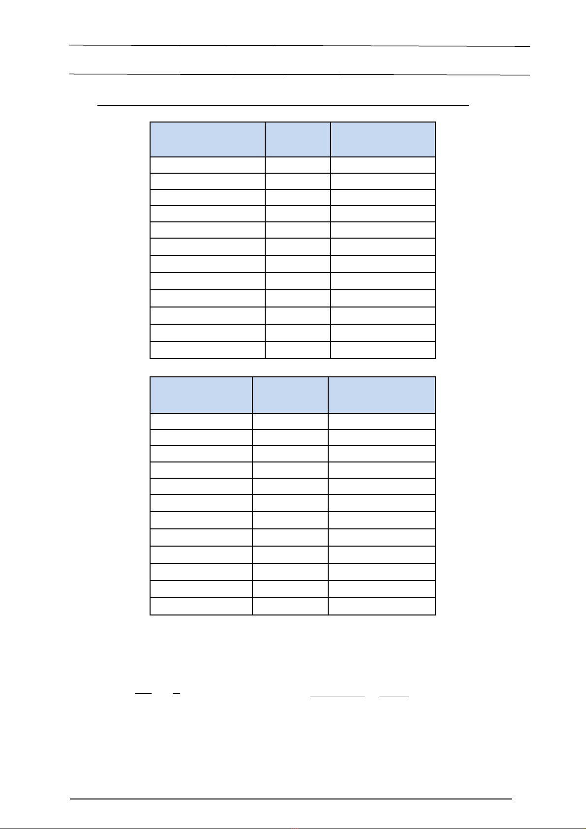
Typical capacitance of the DC-connection inside the power feedback unit:
REVCON
®
-type Power
[kW]
DC-capacity
[µF]
RHD B0 400V 7 20
RHD B0 400V
13 20
RHD B0 400V
18 100
RHD B0 400V
24 40
RHD B0 400V
30 40
RHD B0 400V
50 220
RHD B0 400V
70 220
RHD B0 400V
100 660
RHD B0 400V
125 440
RHD B0 400V
150 660
RHD B0 400V
200 660
RHD B0 400V
250 880
Table 3.5.1
REVCON
®
-type Power
[kW]
DC-capacity
[µF]
RHD D0 400V 8 100
RHD D0 400V
14 100
RHD D0 400V
19 100
RHD D0 400V
25 100
RHD D0 400V
31 100
RHD D0 400V
51 220
RHD D0 400V
71 440
RHD D0 400V
101 660
RHD D0 400V
126 660
RHD D0 400V
151 1760
RHD D0 400V
201 1760
RHD D0 400V
251 1980
Table 3.5.2
Example:
C=200µF, ∆U
GL
=100V, i=271A, a=80mm, r=8,5mm, µ
0
=1,257
.
10
-6
H/m
⇒l
max
=26m
For longer DC-Bus-wires additional capacitors have to be installed (please get in contact
with our application-department if the occasion arises).
(
)
25,0ln´
0
+= ⋅µ
r
a
l
L
π
L
L
L
i
UC
l
ZKDGL
′
−
′
⋅
∆⋅
=
2
2
max
ˆ
This manual suits for next models
2
Table of contents
Popular Industrial Electrical manuals by other brands


Murata
Murata GRM155R71C472KA01 Series Reference sheet

SEW-Eurodrive
SEW-Eurodrive MOVIGEAR classic MGF**1-DSM-C Series operating instructions

Murata
Murata GRM033C80J473KE19 Series Reference sheet

Eaton
Eaton 10250T/E34 Instructional Leaflet

Murata
Murata GRM1885C1H271GA01 Series Reference sheet

Murata
Murata GRM0225C1E6R0CDAE Series Reference sheet

Murata
Murata GRM0335C1E8R6DA01Series Reference sheet

Siemens
Siemens MFKE Series installation instructions

Moeller
Moeller LCB2 Series installation instructions

Zimmer
Zimmer GEP5000 Series Installation and operating instructions

Murata
Murata GRM31CR60J226KE19 Series Reference sheet

Murata
Murata GRM0225C1E9R5WA03 Series Reference sheet