7
LP-420 REV. 2.14.20
FIGURE NOTES:
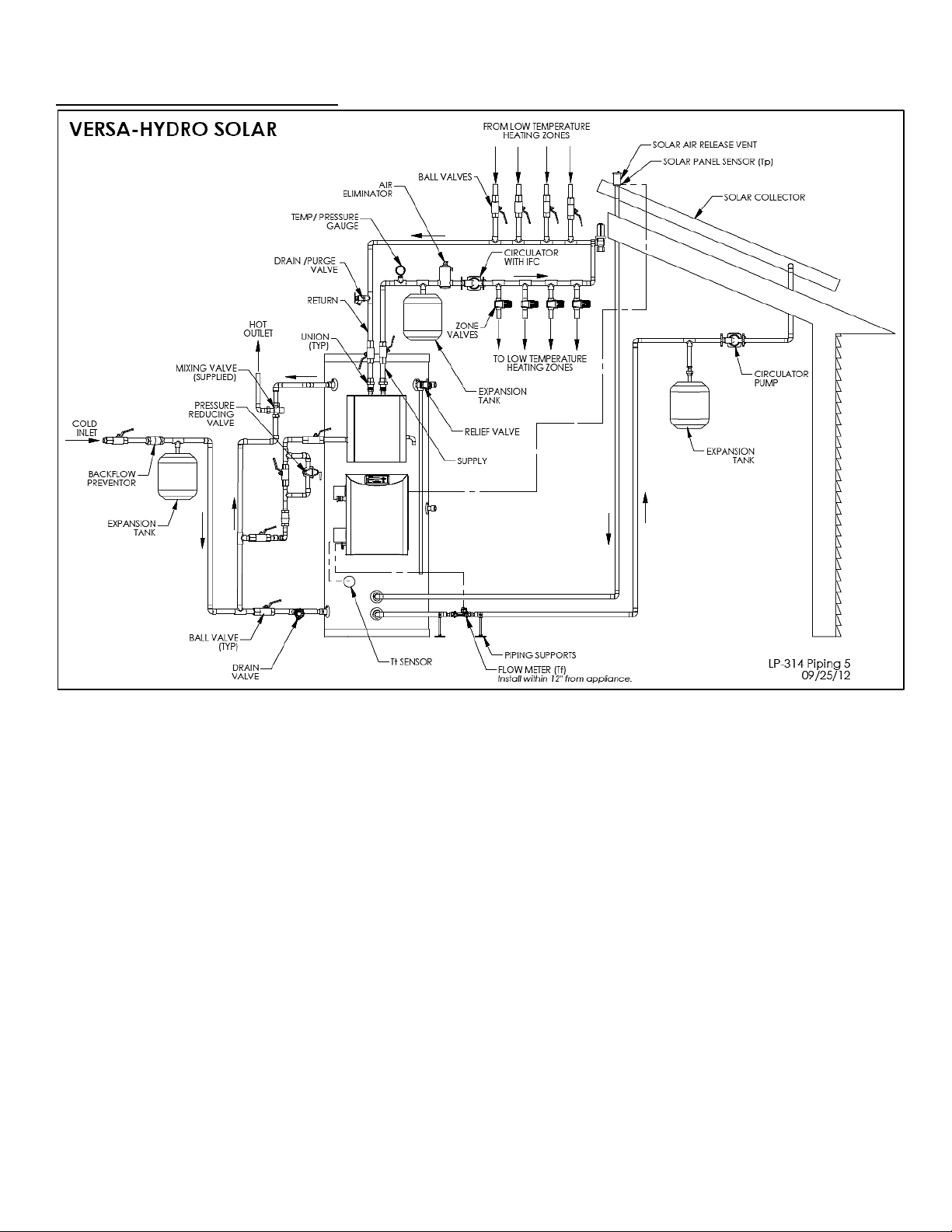
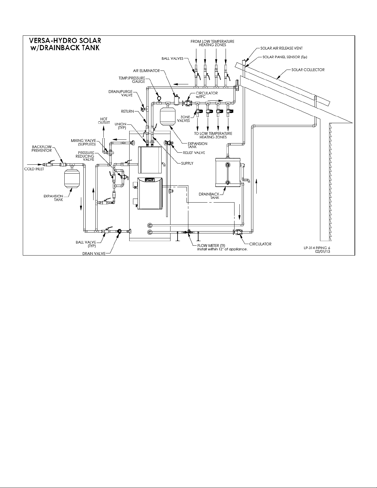
1. This drawing is meant to show system piping concept only. The installer is responsible for all equipment and detailing by local codes.
2. Antifreeze, non-potable HTF shall be used for the solar heat exchanger circuit only. Never introduce antifreeze solution to any connection
other than the solar loop.
3. If there is a check valve on the cold water feed line, a thermal expansion tank suitable for potable water must be sized and installed within
this piping system between the check valve and cold water inlet of the solar water heater.
4. An ASSE 1017 mixing valve is required per SRCC OG-300.
5. A minimum of 12 diameters of straight pipe must be installed upstream of all circulators.
6. Make sure tank is fully purged of air before power is turned on to the backup heat source.
7. Circulators shown in the above hydronic piping should have an integral flow check or alternately use a stock pump with an external spring
type check valve. (Due to extreme temperatures, circulators with integral flow checks are not to be used in solar systems. If circulator comes
equipped with an integral flow check, remove it.)
8. Non-vertical drain back solar system piping should pitch ¼” per foot to facilitate draining.
9. No check valves are allowed within the solar loop.
10. Solar pumps must be installed 3’ below the drain back tank.
11. The drain back tank must be properly supported.
12. The flow meter must be properly supported and installed no more than one (1) foot from the Versa Hydro.
STEP 4: PROGRAMMING THE SYSTEM
NOTE: Programming the control is not possible when the unit is firing. Make sure any input (such as the thermostat) is turned off, so
the water heater will remain idle to allow programming.
To access the system setting program, press and hold the ENTER Key for 4 seconds, until the display
shows the screen at left.
Using the arrow keys on the display, log in your System Menu Access Code “925”. To confirm code,
press ENTER to access system setting program navigation menu.
Table 2 – System Settings
Once the System Menu Access Code is confirmed, the user can set System Parameters. Use the arrow keys on the display to
navigate through the different program settings. To change an appliance setting, press ENTER. Increase system settings by pressing
▲and decrease by pressing ▼on the display.
Listed below are the system settings that can be programmed into the control.