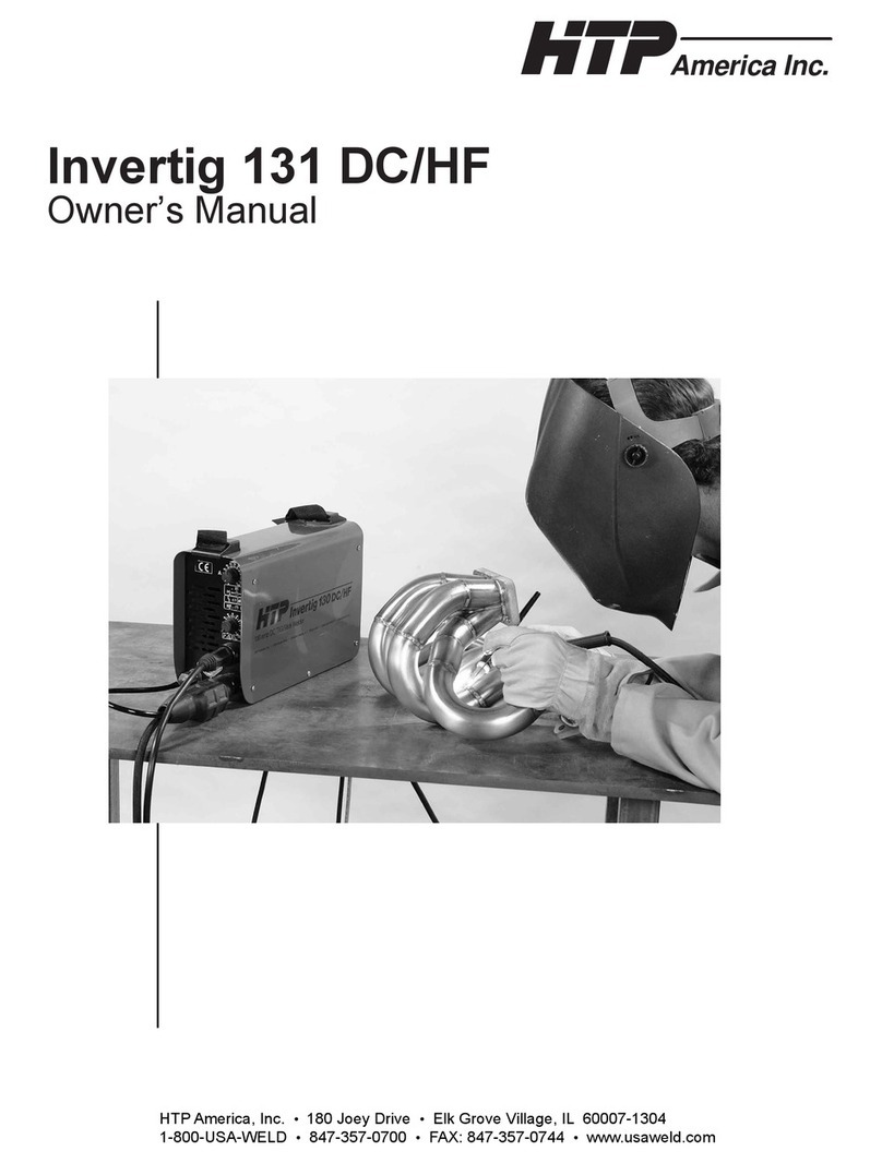
HTP Invertig 130 DC/HF User manual

Invertig 130 DC/HF
Owner’s Manual
America Inc.
HTPAmerica, Inc. •3200 Nordic Road •Arlington Heights, IL 60005-4729
1-800-USA-WELD •847-357-0700 •FAX: 847-357-0744 •www.usaweld.com

Manufacturer’s Warranty
It is expressly agreed that there are no warranties, expressed or implied, made by either the
Salesman, Dealer, or HTP America, Inc. on products or parts furnished hereunder, except the
Manufacturer’s Warranty against defective materials or workmanship as follows:
HTP America, Inc. warrants each new welding machine to be free from defects in material and
workmanship under normal use and service for one year after delivery to the original purchaser.
HTP America, Inc. will repair and replace, at its factory, any part or parts thereof, products to be
returned to HTP America, Inc. with transportation charges prepaid and which its examination shall
disclose to its satisfaction to have been thus defective. This warranty being expressly in lieu of all
other warranties, expressed or implied, and all other obligations or liabilities on its part and it neither
assumes nor authorizes any other person to assume for it any other liability in connection with the
sale of its machines.
This warranty shall not apply to any welding machine which has been repaired or altered by
unauthorized service departments in any way so as in the judgment of HTP America, Inc. to affect
its stability and reliability, nor which has been subjected to misuse, negligence or accident.
HTP America, Inc. shall not be liable in any event, unless HTP America, Inc. receives notice of
alleged breach of warranty within not more than 30 days after the discovery, actual or construction
alleged breach of warranty specifying the claimed defect.
HTP America, Inc. has reserved the right to make change in design or add any improvements to its
products at any time without incurring any obligation to install same on equipment.
This warranty is void unless warranty card is sent to HTP America, Inc. within 15 days from date
of purchase.
Note:
Exclusions to Warranty:
1. The Tig Welding Torch is warranted for a period of ninety
(90) Days against defects in material and workmanship.
2. The tungsten, collet, collet body, ceramic nozzles are
consumable items, WHICH CARRY NO WARRANTY.

For more information, refer to the following standards and
comply as applicable.
1. ANSI Standard Z49.1 SAFETY IN WELDING AND
CUTTING, obtainable from the American Welding Society,
2051 NW 7th St., Miami, FL 33125.
2. ANSI Standard Z87.1 SAFE PRACTICE FOR
OCCUPATION AND EDUCATIONAL EYE AND FACE
PROTECTION, obtainable from American National
Standards Institute, 1430 Broadway, New York, NY 10018.
3. America Welding Society Standard A6.0 WELDING AND
CUTTING CONTAINERS WHICH HAVE HELD
COMBUSTIBLES, obtainable same as item 1.
4. NFPA STANDARD 51. OXYGEN-FUEL GAS SYSTEMS
FOR WELDING AND CUTTING, obtainable from the
National Fire Protection Assoc., 470 Atlantic Avenue,
Boston, MA 02210.
5. NFPA Standard 51B. CUTTING AND WELDING
PROCESSES, obtainable same as item 4.
6. CGA PAMPHLET P-1. SAFE HANDLING OF
COMPRESSED GASES IN CYLINDERS, obtainable
from the Compressed Gas Association, 500 Fifth Avenue,
NewYork, NY 10036.
7. OSHA Standard 29 CFR, Part 1910, Subpart Q WELDING,
CUTTING AND BRAZING.
Safety Suggestions
Electric arc welding produces ultra-violet rays, which are
harmful to skin and eyes. Ultra-violet radiation can penetrate
lightweight clothing, reflect from light colored surfaces, and
burn the skin and eyes. Wear flameproof welding gloves which
are not oily or greasy. The oil or grease on the gloves may
ignite. Wear a heavy, pocket-less; long sleeve shirt, cuffless
trousers, and high-topped work shoes. Wear a full-face welding
helmet with a number eight or darker lens and a cap. These
precautions will protect eyes, hair, face, and skin from arc rays
and hot material.
- To avoid fire, do not weld on wood, plastic tile, or carpeted
floors. Concrete or masonry floors are safest.
- Do not weld on drums, barrels, tanks or other containers until
they have been cleared as described in AWS Standard A6.01.
- Provide adequate ventilation in the welding area at all times.
Do not weld on galvanized zinc, cadmium or lead beryllium
materials unless POSITIVE sufficient ventilation is provided.
These materials produce toxic fumes.
- Do not weld in areas close to degreasing or spraying
operations. Chlorinated hydrocarbon vapors may react with
the ultra-violet rays and form highly toxic phosgene gas.
- If you develop momentary eye, nose or throat irritation during
welding, stop welding immediately. This is an indication that
ventilation is not adequate. Do not continue to weld until
ventilation is improved.
- Exposed, electrically hot conductors or other bare metal in
the welding circuit, or ungrounded electrically hot equipment
can fatally shock a person whose body becomes a conductor.
Do not stand, sit, lie, lean on or touch a wet surface when
welding.
- Frequently inspect cables for wear, cracks, and damage.
Replace those with excessively worn insulation to avoid a
possible lethal shock from bared cable.

Electrical Connection
Your Invertig 130 DC/HF requires a single-phase 230-volt
power supply wired for 16 amps.
Should you remove the plug to install your own plug, the
yellow-green wire is the ground wire and the blue and brown
wires are the hot leads.
All electrical connections should be performed by a qualified
electrician in accordance with the National Electrical Code and
local codes and ordinances.
Front Panel Controls (See Fig. 1)
1) Amperage Adjustment Knob
This knob determines the maximum welding amperage.
The amperage on your Invertig 130DC/HF adjusts from 5 to
130 amps.
When using a remote amperage control, the amperage
adjustment knob is used to limit the maximum amperage for
your particular welding application. For example, when
welding .060" mild steel, I adjusted the amperage knob to 80
amps. This is about 20% more power than I need for welding
the .060" steel. When I depress the foot pedal completely, the
maximum amperage will now be 80 amps.
Setting the machine so the maximum amperage is 80 amps vs.
the maximum output of the machine of 130 amps, the pedal
becomes less sensitive. More of a movement in the pedal
results in a smaller variance of the amperage, making it easier
to control the heat and therefore easier to control your puddle.
2) Welding Mode Switch
The welding mode switch allows you to select the welding
mode of your Invertig 130DC/HF.
A. TIG 2T Mode- With the torch trigger or foot pedal depressed,
your Invertig 130DC will start the arc. When the trigger is
released, the unit will stop. Select this welding mode for
operation with the foot pedal or the torch mounted amperage
control. This will generally be the most common mode of
operation.
B. TIG 4T Mode - This is like a lock on trigger on a drill or
grinder. This mode is generally used with a TIG torch which
has a trigger to start and stop the arc. It is generally not used
with a foot pedal or a torch mounted amperage control.
When you depress the trigger on the torch, your
Invertig
130DC/HF
provides pre-gas flow for as long as the trigger is
depressed. When the trigger is released, it will slope up to the
welding amperage that has been selected. When the trigger is
depressed again, the welding current will slope down. When
the trigger is released, the arc will extinguish, and the post flow
will start.
Fig 1 - Front Controls

We do not recommend using the 4t mode with either the foot
pedal or the torch mounted amperage control.
C. Stick Welding – This mode is used when stick electrode
welding. The electrode will always be hot and the gas solenoid
will not operate.
3) Thermoswitch Indicator Lamp
The thermoswitch indicator lamp will light up yellow when
the duty cycle of your Invertig 130DC/HF has been exceeded.
When this lamp is illuminated, the machine will no longer
weld because the machine has overheated. Leave the machine
plugged in and turned on so the cooling fan can cool the unit
down. Allow the machine to cool for 15 to 30 minutes, the
thermoswitch should reset automatically and your Invertig
will be ready to weld.
4) Power Indicator Lamp
This lamp is illuminated green when the On-Off switch on the
back of your Invertig 130DC/HF is turned on.
5) Touch Start/HF Switch
When the touch start/HF switch is in the HF position, the arc
is initiated by a high frequency pilot arc which allows the arc
to start without bringing the tungsten in contact with the work.
When the foot pedal is depressed, a high frequency arc will
jump from the tungsten to the ground, initiating the arc. This
makes it very easy to start the arc.
When the touch start/HF switch is in the “Lift” position, the arc
is initiated by touching the tungsten to the work and then lifting
it off the work. The lift arc mode allows you to initiate the
welding arc without high frequency. This is important in any
environment where the high frequency arc will cause
interference with sensitive electrical components or computers.
A good example of this would be stainless steel repair in
hospitals.
To TIG Weld using the touch start mode, simply touch the
tungsten to the workpiece, activate the torch trigger or depress
the foot pedal and lift off. When the tungsten breaks contact
with the work, the arc will start.
6) SLOPE DOWN or ARC FORCE
This knob allows you to adjust the slope down time from
0.1 sec to 10 sec where 0 is 0.1 sec and 100 is ten seconds.
This is the amount of time it will take for the welding amperage
to go from the welding amperage to the final current.
NOTE: If you are using a torch mounted remote amperage
control or a foot pedal, it is advisable to set the slope down time
to 0, as you are controlling the slope down manually with your
remote amperage control or foot pedal.
In the stick welding mode, this controls the Arc Force. The arc
force is how “hard” or “soft” the arc is. The minimum setting
(0) produces a softer arc, while the maximum setting (100)
produces a “harder” arc with more “driving” force behind it.
The “harder” arc may produce more spatter.
7) Positive Output Receptacle
When TIG welding, this is where the ground cable connects to
the front of the TIG Adapter. That’s right, we said the ground
cable. This is called straight polarity, with the torch negative
and the work positive.
When Stick Welding Direct Current Electrode Negative
(DCEN), the ground cable will be plugged into the positive
output receptacle. When Stick Welding Direct Current
Electrode Positive (DCEP), the electrode holder will be plugged
into the positive output receptacle.
To install a cable into the positive output receptacle, insert the
male end of the cable into the positive output receptacle and
twist clockwise until snug.
8) 3 Pin Trigger Connection
This connection is used with TIG torches, which have on/off
triggers on the torch. Your Invertig 130DC/HF comes standard
with a footpedal which has the on/off function built into the
pedal, so an on/off trigger on the TIG torch is not necessary.
Therefore, this connection is not used.
9) Gas Output Connection
This is where you connect the gas fitting from the TIG Torch.
The gas output is controlled by the solenoid valve, which is
mounted inside the welder
10) Negative Output Receptacle
When TIG welding, this is where the TIG Torch connects to
your Invertig 130DC/HF Welder. That’s right, we said the TIG
Torch. This is called straight polarity, with the torch negative
and the work positive. When using your Invertig Welder to
TIG weld, all work will be done in straight polarity.
When Stick Welding Direct Current Electrode Negative
(DCEN), the optional electrode holder will be plugged into the
negative output receptacle. When Stick Welding Direct Current
Electrode Positive (DCEP), the ground cable will be plugged
into the negative output receptacle
To install a cable into the negative output receptacle, insert the
male end of the cable into the negative output receptacle and
twist clockwise until snug.

Rear Panel Controls
1) On-Off Switch
This switch controls the input power to your Invertig 130DC/HF
Welder. 0 is off and 1 is on.
When you turn the machine on, the power indicator lamp (#4)
will be illuminated green on the front panel of the welder. This
is an indication your Invertig 130DC/HF is on and ready for
use. If both the yellow thermo switch light (#3) and the green
power indicator light are on when you first turn the machine on,
it is a good indication that you have lost a leg of your 220.
2) Gas Connection
Connect the gas hose which is supplied with the machine to
the barbed gas connection fitting using the crimp type clamp
supplied with your welder. Connect the other end of the hose
to the regulator or flowmeter.
3) Remote Amperage Connection
This is where you will connect the foot pedal or the hand
amperage control. This will allow you to remotely control the
amperage of the welder
Shield Gas
TIG welding requires a shield gas of 100% Argon. A shield gas
is used to keep the surrounding atmosphere from coming in
contact with the molten weld puddle. The correct flow rate is
enough gas to shield the molten weld puddle and protect the
tungsten electrode. Any greater flow rate is a waste of shield
gas. Usually, the flow rate will be set anywhere between 15 and
30 cubic feet per hour (cfh).
Use a flow gauge such as HTP Part #12020 or a flow meter
such as the HTP Part #12020F which is compatible with
Argon cylinders and has a barbed fitting for the delivery hose.
Connect the gas hose to the gas fitting at the rear of the machine
and to the barbed fitting on the regulator.
HTP also has available small 60 cubic foot gas bottles
(Part #99900), which are ideal for use with your welder. These
bottles stand approximately 30" high and weigh less than 40
pounds, making your welder very easy to move around the shop.
Be sure to check with your local gas supplier about filling these
tanks before ordering.
If you already have a large cylinder, you can fill the small
cylinder from the large cylinder using the transfer manifold
(HTP Part #99905).
Fig 2 –
Rear Panel Controls
Fig 3 –
Flow Gauge and
Flow Meter
Fig 4 –
Flow Gauge and
55 Cu ft Gas Bottle

Tungsten Electrodes
HTP recommends the following premium quality tungsten
ground to a high quality finish for use with your Invertig
130DC/HF. All Tungsten is 7" long and can be purchased
individually.
2% Thoriated Tungsten (TT2) – red tip – This tungsten is the
most common tungsten currently used. Generally used for DC
welding of steel and stainless steel. Draw back is it has a low
level radiation hazard. Offers good overall performance.
2% Ceriated Tungsten (TC2) – grey tip – 2% Ceriated is an
excellent substitute for 2% thoriated tungsten and works
excellent with inverter power sources such as your 130DC/HF.
More popular for thinner materials because it requires less
amperage to start. Offers a stable arc.
2% Lanthanated Tungsten (TL2) – blue tip – 2% lanthanated is
also an excellent substitute for 2% thoriated tungsten. It offers
good arc starting characteristics and longer life than 2%
thoriated.
Tungsten Type Diameter
.040" 1/16" 3/32" 1/8"
(1.0mm) (1.6mm) (2.4mm) (3.2mm)
2% Thoriated TT2-7040 TT2-7116 TT2-7332 TT2-718
2% Ceriated TC2-7040 TC2-7116 TC2-7332 TC2-718
2% Lanthanated TL2-7040 TL2-7116 TL2-7332 TL2-718
Amperage 15-50 50-120 80-150 130-250
The electrode should be sharpened to a point with a fine
grinding wheel. If the stone used for sharpening the electrode
is not clean, contaminants could lodge in the electrode and
dislodge when welding. The grinding wheel used for tungsten
electrodes should not be used for any other materials. When
grinding the electrode to a point, a 15 to 30 degree angle is
desired. The grinding marks should run lengthwise with the
point, opposed to in the direction of the diameter.
The HTP Tungsten Sharpener is an excellent tool for precisely
sharpening tungsten electrodes without any fear of
contamination.
General Welding Parameters
Following are some “rule of thumb” welding parameters,
tungsten diameters and amperage settings for welding different
thicknesses of steel. Keep in mind these are general settings
and the specific application may require more or less power to
get the job done.
Mild Steel
Tungsten Machine Welding Filler
Thickness Diameter Amperage Amperage Diameter
.030" .040" 50 30-40 .035"
.050" 1/16" 70 45-55 .035"
.062" (1/16") 1/16" 80 55-65 1/16"
.093" (3/32") 1/16" 110 80-90 1/16"
.125" (1/8") 1/16"-3/32" 130 110-120 1/16"
.187" (3/16")* 3/32" 130 130 1/16"
* May require beveling – depends on joint
Filler Rod for TIG Welding
HTP offers you high quality filler rods in affordable quantities.
All filler rod is packaged in 1lb airtight plastic tubes to keep
your filler rod fresh and contaminant free. The tubes are
completely re-sealable.
In TIG welding, the filler rod is fed into the molten puddle by
hand. The choice of filler rod is extremely important as the rod
must correctly match the material and alloy you will be welding.
The thickness of the material to be welded determines the
diameter of the filler rod.
Fig 5 –
Tungsten Electrodes
Fig 6 –
HTP Tungsten Sharpener
Fig 7 –
Tig Filler Rod

8
Here are some good rules of thumb to help you select the
correct filler metal:
1) ER70S-6 is generally used for mild steel welding.
2) ER70S-2 is highly recommended for welding 4130
chrome-moly tubing in many applications.
3) ER80S-D2 is recommended for welding 4130 chrome-moly
tubing if a higher strength, less ductile weld is required. If
your weld will be heat treated to obtain optimum strength,
then use a filler metal which matches the chemistry of your
tubing, which neither 70S-2 nor 80S-D2 wires do.
4) Generally speaking, use a 1/16" diameter filler rod for
applications where the material is 1/8" and less. Use a 3/32"
diameter rod for 1/8" and thicker.
The following Filler Rod is available from HTP in 1 lb. tubes
which are tightly sealed to prevent oxidation.
Filler Rod
Part # Material
308L-035-1 308L Stainless Steel Wire .035" x 36"
308L-1/16-1 308L Stainless Steel Wire 1/16" x 36"
70S6-1/16-1 ER70S-6 Steel Wire 1/16" x 36"
70S6-3/32-1 ER70S-6 Steel Wire 3/32" x 36"
70S2-1/16-1 ER70S-2 Steel Wire 1/16" x 36"
80SD2-1/16-1 ER80SD-2 Steel Wire 1/16" x 36"
Quick Set Up
1) Welding Mode in 2T for foot pedal.
2) Slope down – 0
3) Touch Start/HF set to HF
4) Ground clamp plugged into Positive receptacle
5) TIG Torch into Negative receptacle
6) 100% Argon Gas Flow to 20 CFH
TIG Welding with your 130 DC/HF
In order to TIG weld, install TIG welding torch (SR9-12) on the
machine. Generally speaking, except for very rare instances,
you will TIG weld DCEN, or DC electrode negative. Plug the
tig torch into the negative output receptacle (#10) and connect
the female gas nut onto the gas outlet (#9) on the front of the
machine. Do not use teflon tape or any other sealers, as the
threads do not seal the connection. Use 100% argon shielding
gas set at approximately 20 cfh. Plug the ground cable into the
positive output receptacle (#7).
Setting up the torch
Lets assume we will be welding some .060" mild steel.
Selecting a 1/16" 2% Ceriated tungsten, we grind a point on
the end of the tungsten (remember always grind the tungsten
longitudinally, never radially). Select a 1/16" collet and insert
the tungsten so the pointed end of the tungsten comes out
through the slit in the collet. Next insert the collet/tungsten
assembly into the threaded end of the collet body, so the pointed
end of the tungsten comes out through the sized hole of the
collet body. (See Fig 8) Thread the assembly into the torch head
and tighten the collet body snugly by hand. Install the back cap,
but do not tighten at this point. Install a #6 alumina cup on the
collet body and tighten snugly by hand. Have the tungsten
protruding from 2 to 3 times its diameter from the end of the
cup (in this instance 1/8" to 3/16" (See Fig 9). Tighten the
back cap.
Holding the Torch
It is recommended that you use TIG welding gloves like our
BL25 gloves. These are thinner than standard welding gloves
and will give you a much better “feel” and make it easier to
work the filler rod. Grip the torch somewhat like a pencil, as
indicated in figure 10. The torch must be positioned almost
perpendicular to the work and in such a manner that the
tungsten is kept 1/8" to 1/4" off the work. The tungsten should
only contact the work when starting the arc. Once the arc is
started, the tungsten should never contact the work. Use the
edge of your hand and little finger to hold the torch steady.
Fig 8 – Assembly order for Torch Parts
Fig 9 – Tungsten Stickout

Set the amperage to about 60 amps on the amperage selector
(#6). Connect argon to the machine and set the flow rate to
about 20 cfh. Set the welding mode switch (#2) to the 2T
position. Set the Touch Start/HF switch to HF. Depress the foot
pedal to start the current flow and the shield gas. Pushing the
pedal further gives you more amperage, which gives you more
heat. Depress the pedal so you get a molten puddle about 3/16"
diameter. Initially, just practice moving the tungsten in a straight
line, at a constant speed, with a constant bead width, and
keeping it a constant distance off the work piece. Remember
that Rome wasn’t built in a day, so don't expect to master TIG
welding in 15 minutes. PRACTICE, PRACTICE, PRACTICE.
Once you have mastered just running a bead in a straight line
without adding any filler metal, the next step is to do the same
thing but to add filler metal. Dip the filler metal into the
molten puddle (do not try to melt the filler metal into the work)
and NEVER allow the filler metal to touch the tungsten. If
the filler metal comes in contact with the tungsten, or if the
tungsten contacts the work, you must stop and sharpen the
tungsten. Remember, practice, practice, and practice.
To make my life easier, and so I am not always stopping to
sharpen tungsten, I keep a package of 10 tungsten of each
diameter sharpened in the box. That way, when I need a new
tungsten, I can just take a sharp one and put the contaminated
one in the box. When I have used them all, I will sharpen them
all at once.
Now, once you have practiced laying a bead and adding filler
metal, then you can practice welding two pieces of metal
together. Start with a butt weld, as this is the easiest. Master
this technique before you continue to other joints. Compared
to MIG welding, TIG welding is much harder and will require
a lot of practice to become proficient.
Arc Welding with your Invertig 130 DC/HF
You can arc weld with your Invertig 130 DC/HF if you have
purchased the optional electrode holder # 22315-ARCMTS. If
you will be welding Electrode Negative (Straight Polarity) insert
the electrode holder into the negative output receptacle and the
ground cable into the positive output receptacle. If you will
be welding Electrode Positive (Reverse Polarity) insert the
electrode holder into the positive output receptacle and the
ground cable into the negative output receptacle.
Make sure material you are welding is clean, and attach the
ground cable to the workpiece. Select the correct rod type,
diameter and amperage for your application. (See Fig 11)
To strike the arc, drag the electrode across the work as if you
were trying to strike a match. Lift the electrode off the work
slightly. If the electrode sticks to the work, give it a sharp twist
to break it free. If the arc goes out after it has started, you have
lifted the electrode too high off the work. Try to incline the
electrode at a 10 deg to 30 deg angle from perpendicular in the
direction of motion.
Set the arc force to a setting which you find fits your particular
welding application.
Fig 11– Electrode Selection Guide
Fig 10 –
Holding the Torch
Electrode Polarity Penetration Position Diameter 40 50 60 70 80 90 100 110 120 130 140 150
6010 EP DEEP ALL 3/32"
1/8"
5/32
6011 EP DEEP ALL 3/32"
1/8"
5/32
6013 EP,EN LOW ALL 3/32"
1/8"
5/32
7014 EP,EN MEDIUM ALL 3/32"
1/8"
5/32
7018 EP LOW ALL 3/32"
1/8"
5/32
7024 EP,EN LOW FLAT 3/32"
1/8"
308L EP LOW ALL 3/32"
1/8"
5/32
Amperage Range
Electrode Selection and Amperage Range

Pyrex Cup Kits
Nothing makes welding easier than being able to see what
you are doing. HTP’s Pyrex Cup kits do just that! The clear
Pyrex cup gives you unparalleled visibility of the arc and
work. The Pyrex Cup kit also comes standard with our
special gas saver gas lens kit. This unique system saves gas
while at the same time providing better gas coverage with a
more even and uniform gas flow. Eliminates gas turbulence
which can cause weld quality problems. Pyrex cup kits are
available to fit all standard torches. There is even a special
large diameter kit available for welding titanium.
Large Diameter Pyrex Cup Kits
Tungsten Diameter
Illus # Description 0.040" 1/16" 3/32" 1/8" Price
9 and 20 Series Tig Torches
1 Heat Shield 2HSGSLD 2HSGSLD 2HSGSLD 2HSGSLD
2 Wedge Collet PYR20C040 PYR20C116 PYR20C332 PYR20C18
3 Collet Body PYR20LDCB PYR20LDCB PYR20LDCB PYR20LDCB
4 Tungsten Adapter PYR040TA-LD PYR116TA-LD PYR332TA-LD PYR18TA-LD
5 Pyrex Cup PYR20LD PYR20LD PYR20LD PYR20LD
Complete Kit PYREX20LD-040 PYREX20LD-116 PYREX20LD-332 PYREX20LD-18
17, 18, and 26 Series Tig Torches
1 Heat Shield 4HSGSLD 4HSGSLD 4HSGSLD 4HSGSLD
2 Wedge Collet PYR17SC040 PYR17SC116 PYR17SC332 PYR17SC18
3 Collet Body PYR17LDCB PYR17LDCB PYR17LDCB PYR17LDCB
4 Tungsten Adapter PYR040TA-LD PYR116TA-LD PYR332TA-LD PYR18TA-LD
5 Pyrex Cup PYR17LD PYR17LD PYR17LD PYR17LD
Complete Kit PYREX17LD-040 PYREX17LD-116 PYREX17LD-332 PYREX17LD-18
Pyrex-Big Parts
10
Pyrex Parts

Tungsten Diameter
Illus # Description 0.040" 1/16" 3/32" 1/8" Price
For 9 and 20 Tig Torches
1 Pyrex Cup PYR8S PYR8S PYR8S PYR8S
2 Tungsten Adapter PYR040TA PYR116TA PYR332TA PYR18TA
3 Collet Body PYR20CB PYR20CB PYR20CB PYR20CB
4 Wedge Collet PYR20C040 PYR20C116 PYR20C332 PYR20C18
5 Heat Shield 2HSGS 2HSGS 2HSGS 2HSGS
Complete Kit PYREX20-040 PYREX20-1/16 PYREX20-3/32 PYREX20-1/8
For 17, 18, and Series 26 Tig Torches
Short Configuration
1 Pyrex Cup PYR8S PYR8S PYR8S PYR8S
2 Tungsten Adapter PYR040TA PYR116TA PYR332TA PYR18TA
3A Collet Body PYR17SCB PYR17SCB PYR17SCB PYR17SCB
3A Wedge Collet PYR17SC040 PYR17SC116 PYR17SC332 PYR17SC18
5A Heat Shield 3HSGS 3HSGS 3HSGS 3HSGS
Complete Kit PYREX17S-040 PYREX17S-1/16 PYREX17S-3/32 PYREX17S-1/8
Standard Configuration
1B Pyrex Cup PYR8L PYR8L PYR8L PYR8L
2 Tungsten Adapter PYR040TA PYR116TA PYR332TA PYR18TA
3B Collet Body PYR17LCB PYR17LCB PYR17LCB PYR17LCB
4B Wedge Collet PYR17LC040 PYR17LC116 PYR17LC332 PYR17LC18
5A Heat Shield 3HSGS 3HSGS 3HSGS 3HSGS
Complete Kit PYREX17-040 PYREX17-1/16 PYREX17-3/32 PYREX17-1/8
Pyrex Cup Parts
11

12
Flex Neck Tig Torch
Need to change the angle of your Tig torch to get into that
tight area? Trouble is, with a standard Tig torch you can’t.
Well, HTP has the answer: our Flex Neck Tig Torch. This
unique torch lets you bend the end of your Tig torch into
virtually any position, allowing you quick, easy access to
practically any tight, cramped or out-of-the-way spot.
Imagine how much easier your welding will be!
Swivelhead
Swivelhead
Action
Table of contents
Other HTP Inverter manuals
Popular Inverter manuals by other brands

Afore
Afore HNS1509TL installation manual

G-Power America
G-Power America GN10000DEW owner's manual

Gree
Gree GMV-120WL/A-T Service manual

MAER IDROPULITRICI
MAER IDROPULITRICI AVANT 120/11 Instructions for installation and use

GW Instek
GW Instek GFG-8020H user manual

Mase
Mase SILENT 5001DM Maintenance manual