Huaray GigE User manual

GigE/10GigE Area Scan Camera
User’s Manual
V1.0.0

I
Foreword
General
This manual introduces the functions and operations of the GigE/10GigE area scan camera
(hereinafter referred to as "the camera").
Safety Instructions
The following signal words might appear in the manual.
Signal Words Meaning
DANGER
Indicates a high potential hazard which, if not avoided, will result in
death or serious injury.
WARNING
Indicates a medium or low potential hazard which, if not avoided,
could result in slight or moderate injury.
CAUTION
Indicates a potential risk which, if not avoided, could result in
property damage, data loss, reductions in performance, or
unpredictable results.
TIPS Provides methods to help you solve a problem or save time.
NOTE Provides additional information as a supplement to the text.
Revision History
Version Revision Content Release Time
V1.0.0 First release. July 2021
Privacy Protection Notice
As the device user or data controller, you might collect the personal data of others such as their face,
fingerprints, and car plate number. You need to be in compliance with your local privacy protection
laws and regulations to protect the legitimate rights and interests of other people by implementing
measures which include but are not limited: Providing clear and visible identification to inform
people of the existence of the surveillance area and provide required contact information.
About the Manual
The contents of this manual are for reference only, and timely update cannot be guaranteed.
Slight differences might be found between the manual and the product. If you have any
questions, please contact the technical support of the corresponding area.

II
We are not liable for losses incurred due to operating the product in ways that are not in
compliance with the manual.
The manual will be updated according to the latest laws and regulations of related jurisdictions.
For detailed information, see the paper user’s manual, use our CD-ROM, scan the QR code or
visit our official website. The manual is for reference only. Slight differences might be found
between the electronic version and the paper version.
All designs and software are subject to change without prior written notice. Product updates
might result in some differences appearing between the actual product and the manual. Please
contact customer service for the latest program and supplementary documentation.
There might be errors in the print or deviations in the description of the functions, operations
and technical data. If there is any doubt or dispute, we reserve the right of final explanation.
Upgrade the reader software or try other mainstream reader software if the manual (in PDF
format) cannot be opened.
All trademarks, registered trademarks and company names in the manual are properties of their
respective owners.
Please visit our website, contact the supplier or customer service if any problems occur while
using the device.
If there is any uncertainty or controversy, we reserve the right of final explanation.

III
Important Safeguards and Warnings
This section describes the contents covering proper handling of the device, hazard prevention, and
prevention of property damage. Read these contents carefully before using the device, comply with
them when using, and keep the manual well for future reference.
Operation Requirements
Transport, use and store the device under allowed humidity and temperature conditions.
Prevent liquids from splashing or dripping on the device. Make sure that there are no objects
filled with liquids on top to avoid liquids flowing into the device.
Do not disassemble the device.
Only use the device within the rated power range.
Make sure that the power supply of the device works properly before use.
Do not pull out the power cable of the device while it is powered on.
Installation Requirements
Observe all safety procedures and wear required protective equipment provided for your use
while working at height.
Do not expose the device to direct sunlight or heat source.
Do not install the device in humid, dusty or smoky places.
Install the device in a well-ventilated place, and do not block the ventilator of the device.
Strictly abide by local electrical safety standards, and make sure that the voltage in the area is
steady and conforms to power requirements of the device.
Use the power adapter or case power supply provided by the device manufacturer.
Connect the device with the adapter before power on.
Do not connect the device to more than one power supply. Otherwise, the device might be
damaged.
The power supply must conform to the requirements of ES1 in IEC 62368-1 standard and no
higher than PS2. Note that power supply requirements are subject to the device label.
Connect the class I electrical appliance to a power socket with protective earthing.

IV
Table of Contents
Foreword............................................................................................................................................................ I
Important Safeguards and Warnings............................................................................................................. III
1 Product Information...................................................................................................................................... 1
Overview ....................................................................................................................................................................................... 11.1
Features ......................................................................................................................................................................................... 11.2
Typical Networking Topology................................................................................................................................................ 11.3
Operating Environment........................................................................................................................................................... 21.4
2 Installation..................................................................................................................................................... 3
Downloading the Client .......................................................................................................................................................... 32.1
Connecting Camera .................................................................................................................................................................. 32.2
3 Function Parameter....................................................................................................................................... 5
Frame Rate.................................................................................................................................................................................... 53.1
3.1.1 Influential Facts for Frame Rate ............................................................................................................................... 5
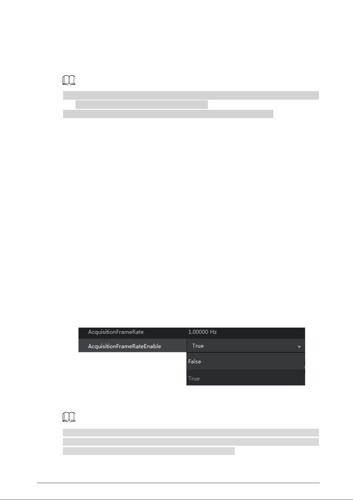
3.1.2 Configuring Frame Rate ............................................................................................................................................. 5
Acquisition mode....................................................................................................................................................................... 63.2
Trigger Mode................................................................................................................................................................................ 63.3
3.3.1 Trigger Type..................................................................................................................................................................... 7
3.3.2 Trigger Source ................................................................................................................................................................ 7
Flat Field Correction.................................................................................................................................................................. 83.4
Trigger Delay..............................................................................................................................................................................103.5
Output Signal ............................................................................................................................................................................113.6
IO Feature....................................................................................................................................................................................123.7
3.7.1 Two-way I/O Circuit....................................................................................................................................................12
3.7.2 Opto-isolated Input ...................................................................................................................................................14
3.7.3 Opto-isolated Output................................................................................................................................................14
IO Smoothing ............................................................................................................................................................................163.8
Black Level ..................................................................................................................................................................................163.9
Gain.............................................................................................................................................................................................173.10
3.10.1 Analog Gain................................................................................................................................................................17
3.10.2 Digital Gain .................................................................................................................................................................17
White Balance..........................................................................................................................................................................183.11
Gamma ......................................................................................................................................................................................193.12
Frequency Converter............................................................................................................................................................203.13
Testimage (Test Mode).........................................................................................................................................................213.14
Cybersecurity Recommendations ............................................................................................. 22Appendix 1

1
1Product Information
Overview1.1
The GigE/10GigE industrial camera adopts high performance photosensitive chip and transmits
non-compressed image data at a speed of gigabit even 10 gigabit through GigE port in real-time. It
complies with GigE Vision protocol and GenICam standard, at the same time 10 GigE camera is
compatible with CameraLink protocol. Meeting the requirements of most industrial applications, the
camera can work stably in various poor environments, which makes it an industrial camera with high
stability at low cost. You can configure parameters and collect data by MV Viewer client.
Features1.2
Global shutter and rolling shutter CMOS.
Strong ISP algorithm supported.
FPN correction is available on certain models.
High image quality.
High performance at low cost.
Functions such as burst mode and sequence mode are available on certain models.
Multiple ROI is available on certain models.
Shutter mode and global reset are available on certain models.
Color camera supports interpolation, white balance, color correction matrix, chromaticity and
saturation.
Outputs multiple image data formats such as ROI, Binning and mirror.
Conform to CE, FCC, UL and RoHS.
GigE supports up to 100 meters transmission distance.
Global shutter high frame rate CMOS models, Global shutter high quality CCD models.
CCD supports static correction, dynamic fusion and Smear inhibition.
CMOS supports FFC.
Defective pixel correction and custom defective data import are available.
Wide voltage input meets the GigE Vision V2.0 protocol and GenICam standard.
PoE and wide voltage 9–24 VDC wide voltage power supply are available on certain models.
Typical Networking Topology1.3
For industrial cameras, the most typical networking method is point-to-point, which means that
between the host and the camera, there is no network media but only a network cable. One host can
connect to multiple cameras through multiple network ports or switches.
NetworkingFigure 1-1

2
Operating Environment1.4
Temperature and humidity.
Environment temperature cannot excess 50°C (122°F), and air conditioner preferred.
Operating temperature: –30°C to +50°C (–22°F to +122°F).
Operating humidity: 20%–80% (non-condensing).
Storage temperature: –30°C to +80°C (–22°F to 176°F).
Storage humidity: 20%–80% (non-condensing).
Install the camera indoor on stable surface with reasonable dissipation space around it.
Air circulation ensured.

3
2Installation
Downloading the Client2.1
Log in to http://download.huaraytech.com/pub/sdk/, download and install MV Viewer onto your
PC.
Connecting Camera2.2
Open MV Viewer to configure and operate on the camera.Step 1 Click all attributes to start configuration.Step 2
Main interfaceFigure 2-1
Table 2-1 Parameter description
No. Parameter Description
1
Menu
See Table 2-2 for details.
2 Device list
Includes GigE, USB, CameraLink and PCLe cameras.
: Click the icon to manually refresh the online device information.
: Device to be connected.
: Device is connected. MV Viewer can only connect and operate on
one camera at a time.
3
Device
information
Interface and device information of the selected device.
4
Image
configuration
Includes video stream, image stream, display stream, image position,
gray level and RGB value.

4
No. Parameter Description
5 Tool bar
/: Play/stop playing. Click and select play mode
among continuous, single frame and multiple frames as needed.
You can only select play mode when the video is paused.
: Save single or multiple frames of images.
/ : Zoom in or out the image.
/: Displays the image in 1:1 ratio or as the window size.
When the image is zoomed in or out, click can restore the image
to windows size.
/: The mirror of image in the vertical or horizontal direction.
6 Window
operation menu
/ / : Maximize/restore/minimize the image window.
: Close MV Viewer.
7
Parameter
information
/: Display or hide all function parameter information.
8
Function
parameters
Select and configure specific function parameters.
9 Operation level
Click to select characters among Beginner, Expert or Guru from
the drop-down list as needed. Each character corresponds to slightly
different sets of parameters.
You can only operate on the images during pause or the image stops.
Table 2-2 Menu parameter description
Menu Description
File
Open File Select File > Open File, and then select a file, click Open.
Open
Recent
Select File > Open Recent, 10 files which have been opened recently
are displayed. Click one file to open it.
Save
Save the changes of the current file.
Save as
Save the current file to a different path with a different name.
Event Event
Notifications for events such as device parameter update, event
message channel and stream cache.
Statistics Statistics
Integrates data such as the configured collection frame rate,
bandwidth, number of received images, frame loss rate and number
of error images.

5
3Function Parameter
This section takes on the functions of the industrial camera.
Industrial cameras support 3 user levels, including Beginner, Expert and Guru. Each
corresponds to slightly different sets of parameters.
Grayed out parameters cannot be changed under the current running mode.
Frame Rate3.1
Frame rate, in area scan cameras, is the number of images the camera outputs every second.
3.1.1 Influential Facts for Frame Rate
Bandwidth: The bigger the bandwidth, the bigger the transmission data volume and the
higher the frame rate.
Pixel format: Different pixel formats takes up different amount of storage. Under the same
environment, the more storage is occupied, the lower the frame rate becomes.
Image resolution: Relates to the camera sensor features, affected by the image size as well.
With the smaller image size, the frame rate gets higher.
Exposure time: The longer the exposure time, the lower the frame rate and vice versa.
3.1.2 Configuring Frame Rate
AcquisitionFrameRateEnable is the parameter for enabling frame rate acquisition. True
means enable and False means disable.
Configure frame rateFigure 3-1
AcquisitionFrameRate defines capture rate of frames.
ResultingFrameRateAbs defines the largest speed of capturing frames allowed.
When the value of AcquisitionFrameRate exceeds that of ResultingFrameRateAbs, the camera
captures images at the frame rate of ResultingFrameRateAbs value. Opposite of that, the camera
captures images at the frame rate of AcquisitionFrameRate value.

6
Acquisition mode3.2
Acquisition mode of the camera includes Continuous, Single Frame and MultiFrame.
Configurations are as follows.
Aqusition modeFigure 3-2
Table 3-1 Description of acquisition mode parameters
Parameter Working Principle
Single Frame The camera starts capturing and stops after one capture.
Continuous The camera starts and keeps capturing.
Manual operation is required for stopping the capture.
MultiFrame
Set the number of frames to be captured in AcquisitionFrameCount (1–255).
The camera starts and keeps capturing.
Manually stop capturing before the set volume is reached.
AcquisitionFrameCount needs to be configured for MultiFrame. Enter a reasonable number as
needed.
Number of capturesFigure 3-3
Trigger Mode3.3
The trigger mode of the camera includes SoftwareTrigger (software trigger) and LineN (hardware
trigger).
For area scan cameras, N is 1 or 2, and for large area scan cameras, it is 5, 6 or 7.

7
3.3.1 Trigger Type
Select FrameStart (frame trigger) or AcquisitionStart (image capture trigger) under
TriggerSelector.
FrameStart: Single frame capture. One trigger signal captures one frame.
AcquisitionStart: Continuous capture. One signal triggers continuous captures.
Trigger TypeFigure 3-4
3.3.2 Trigger Source
Software trigger: Trigger signal comes from software.
Hardware trigger: Trigger signal comes from external devices through I/O port. For the
detailed number of signal channels for each camera I/O port, refer to the electrical
specifications of the camera.
Area scan cameras use the 6-pin cable and large area scan cameras use the 12-pin cable.
Electrical specificationFigure 3-5
Electrical specificationFigure 3-6

8
Enable TriggerMode.Step 1
Set TriggerSource to Software.Step 2
Each click on TriggerSoftware gets a frame.
Software triggerFigure 3-7
(Optional) Set TriggerSource to LineN.Step 3
Each trigger signal from external devices gets a frame.
Hardware triggerFigure 3-8
When hardware trigger is enabled, you can select trigger signal throughStep 4
TriggerActivation.
RisingEdge: Press the trigger board to send trigger signal.
FallingEdge: Release the trigger board to send the signal.
You can send the trigger signal as needed after setting the trigger source.Step 5
Trigger sourceFigure 3-9
Flat Field Correction3.4
The image quality can be affected by uneven light, fixed-pattern noise of the sensor and noise of
uneven responses during using the area scan cameras. FFC (Flat Field Correction) is needed for
these situations.
It is mainly for ensuring image balance when applied to area scan cameras.
FFC contains 2 modes.
Point-to-point: The image after correction is more accurate and even.
Plane-to-plane (16 × 16): Applicable for small area scan cameras.
FFC works by combination of 3 corrections.

9
In dark field, correct fixed-pattern noise.
In Bright field, correct uneven response.
In Bright field, correct uneven lens or light.
The ratio between the maximum and the minimum brightness of the image which needs FFC
cannot exceed 2.
Select Tools > Camtools on the top.Step 1
Camera toolsFigure 3-10
Click FFC at the upper-right corner.Step 2
FFC interfaceFigure 3-11
After entering the FFC interface, there will be step-by-step instructions prompting at theStep 3
lower-right corner.

10
FFC operationFigure 3-12
Follow the on-screen instructions to complete FFC.Step 4
FFCEnable dialog box pops up after completing online FFC with ON/OFF option for you toStep 5
disable it.
After the correction, you can see the difference on the brightness of the dark part of theStep 6
image.
Correction effectFigure 3-13
Trigger Delay3.5
You can set delay time from the camera receiving the trigger signal to responding to the signal to
capture.

11
Principle of trigger delayFigure 3-14
The trigger signal is rising edge in the following figure. The delay time is configured through
Trigger Delay with μs as unit and ranges from 0 μs–1000000 μs, namely, 0 s–1 s.
Configure trigger delayFigure 3-15
Output Signal3.6
GigE camera contains 1 opto-isolated output Line 0 and 1 Line 2 which can be set to input or
output.
Under Digital IO Control, set Line 2 as Line Selector.Step 1
Set Line Mode to Output.Step 2
Set output signal Line2Figure 3-16

12
The output signal triggered by the camera can be used as switch on/off signal to control
external devices such as alarm light, light source and PLC. Trigger signal can be sent out
through electrical level reversal and Output signal. Configure parameters by Digital IO
Control.
IO Feature3.7
3.7.1 Two-way I/O Circuit
Line2 is a bidirectional I/O signal which can be used as an input or output signal.
The external circuit must be able to input up to 2 mA sink current with voltage under 0.8 VDC.
No more than 100 uA sink current for high level input.
Up to 50 mA sink current when the IO port is used as output.
GPIO inputFigure 3-17

13
5 V TTL logic level input circuitFigure 3-18
GPIO outputFigure 3-19
Table 3-2 Electrical specifications of the two-way I/O circuit
Voltage Description
+30.0 VDC Extreme voltage. Output voltage cannot exceed the value. Otherwise, the
device might be damaged.
+3.3 to +24 VDC The security working voltage range when output.
< 3.3 VDC Possible error on I/O output.

14
3.7.2 Opto-isolated Input
Opto-isolator can realize one-way transmission of signal due to that the optocoupler is transmitted
in one way. One-way transmission separates the input and output end completely, which
eliminates the influence output signals have on the input end, leading to high anti-interference
performance and strong working stability of the opto-isolator.
Line1 of the camera I/O signal is opto-isolated input and can sustain up to 25 mA current. For
detailed circuit, see Figure 3-20.
Line1 internal circuitFigure 3-20
Table 3-3 Opto-isolated input circuit description
Input Voltage Description Remarks
30 VDC
Extreme voltage. Input voltage cannot
exceed the value. Otherwise, the device
might be damaged. The 29 mm × 29 mm × 42 mm
GigE camera (products shipped
before January 2017) has an
optocoupler isolation input limit
voltage of 25 VDC, and I/O input
safe working voltage is 0–18
VDC.
0–24 VDC Security working voltage range for I/O
input.
0–1.4 VDC Logic 0.
> 1.4–2.2 VDC
The input status reverses, and the logic
status inside the voltage range is
unsure.
> 2.2 VDC Logic 1.
Avoid the input voltage being inside 1–1.5 V, under which the circuit is not stable.
The breakdown voltage is 30 V. keep the voltage stable.
The sink current of the opto-isolated I/O input port is 5 mA–15 mA.
3.7.3 Opto-isolated Output
Line0 of the camera I/O signal is opto-isolated output. Refer to Figure 3-21 for detailed internal
circuit.

15
Internal circuit of Line0Figure 3-21
The maximum output current of Line0 is 25 mA.
The pull-up resistance value complies with the maximum allowed current of the opto-isolated
output port under the defined voltage.The larger the resistance value, the smaller the optocoupler
forward voltage drop, the more slowly the output wave changes and the weaker the ability to
power external devices. The recommended optocoupler value is 270 Ω, 560 Ω and 1 kΩ when the
voltage is 5 V, 12 V and 24 V respectively.
The rising and falling time, delay time of rising and falling edge are shown as Figure 3-22 when the
pull-up voltage is 1 kΩ.
Delay time of rising and fallingFigure 3-22
The electrical specifications of the opto-isolated output are shown in below table Table 3-4 when
the external voltage is 3.3 V and resistance is 1 kΩ.
Table 3-4 Output trigger time
External
Voltage (V)
Rising Time
tR(us)
Falling Time
tF(us)
Rising Edge
Trigger Delay tDR
(us)
Falling Edge Trigger
Delay tDF (us)
5 19.70 3.20 39.9 8.06
12 24.06 5.22 44.8 11.8
24 30.11 8.10 44.8 53.2
The optocoupler output delay is the time delay from FPGA internal logic output to external
opto-isolated output pin.
Rising edge trigger delay is the time delay from the 10% of the FPGA pin output level to the 90%
of the external output signal amplitude.
Falling edge trigger delay is the time delay from the 90% of the FPGA pin output level to the
10% of the external output signal amplitude.
Rising time is the time delay from the 10% of the external output signal amplitude to 90%.
Falling time is the time delay from the 90% of the external output signal amplitude to 10%.
This manual suits for next models
1
Table of contents