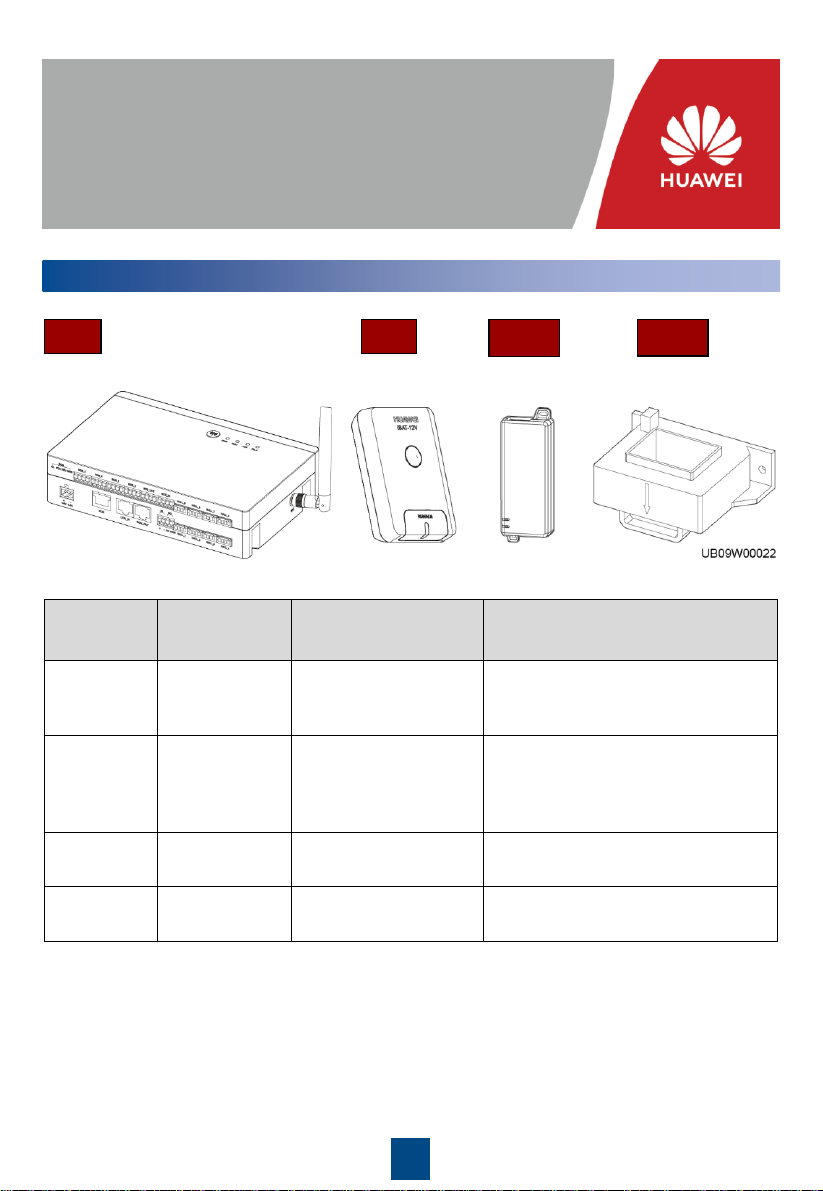
OT terminal
Battery
connecting kit
Bolt
Spring washer
Flat washer
2
2Installing Equipment
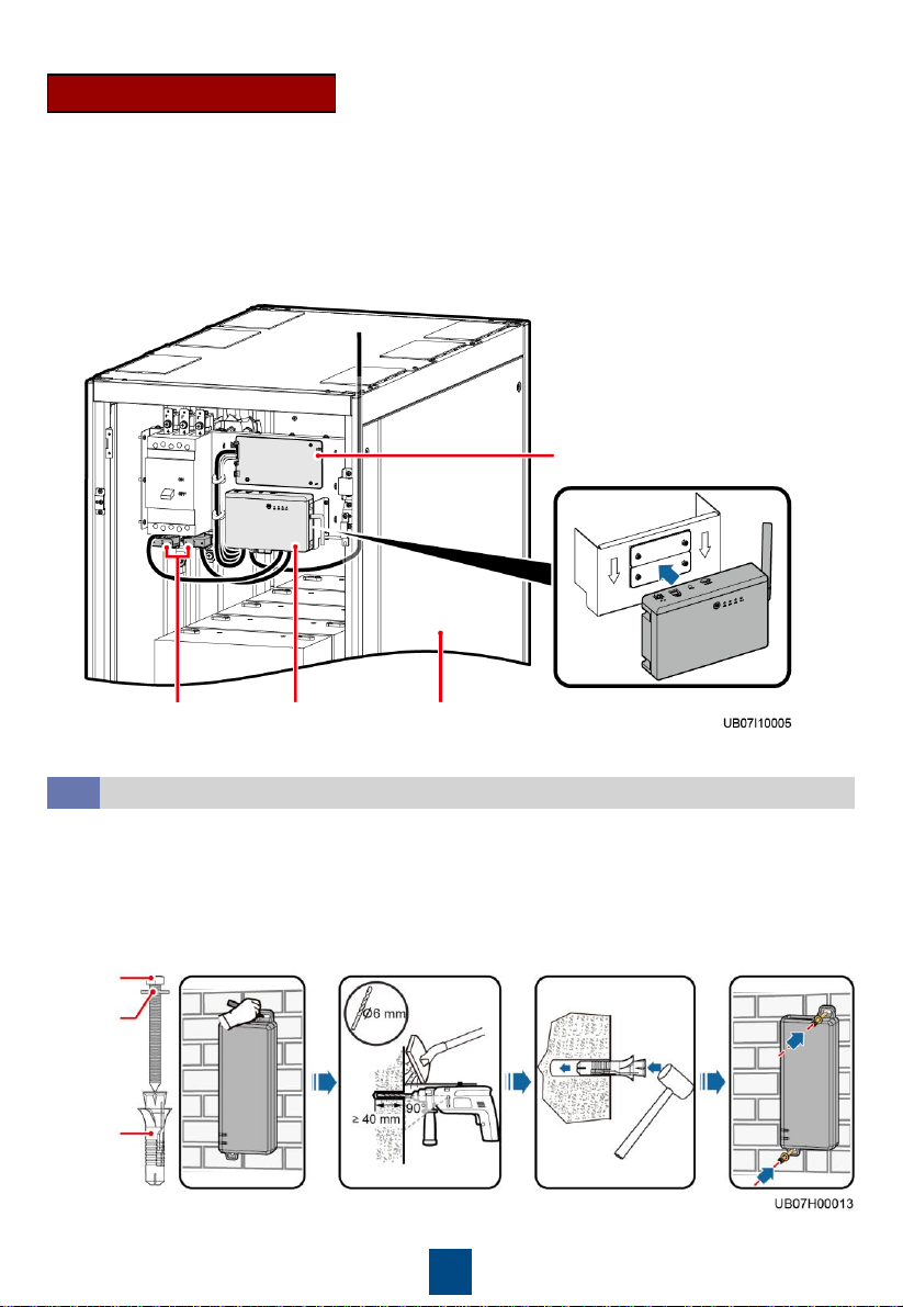
Installing the iBAT
2.1
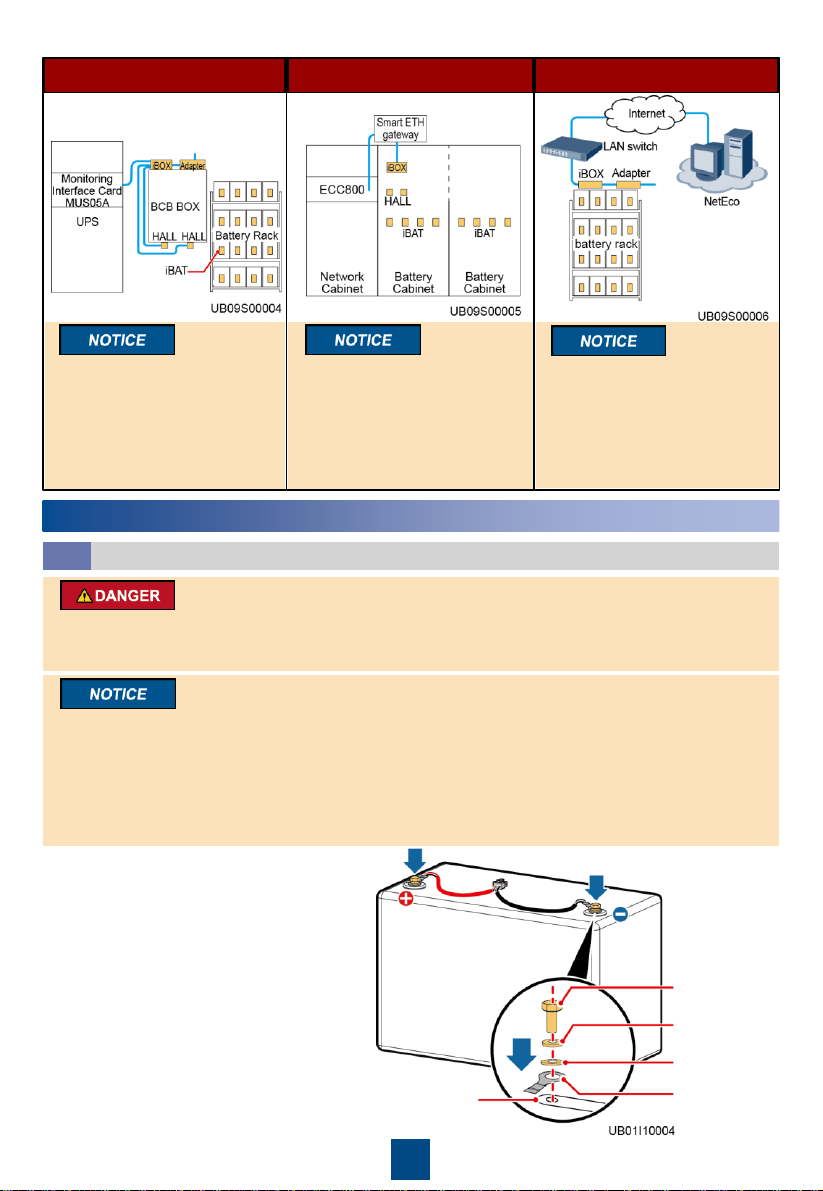
1. Open the battery string switch. Install iBAT
cables on the battery.
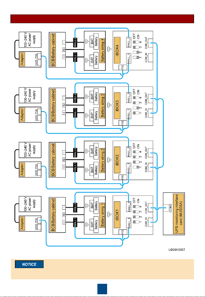
UPS scenario ECC scenario NetEco scenario
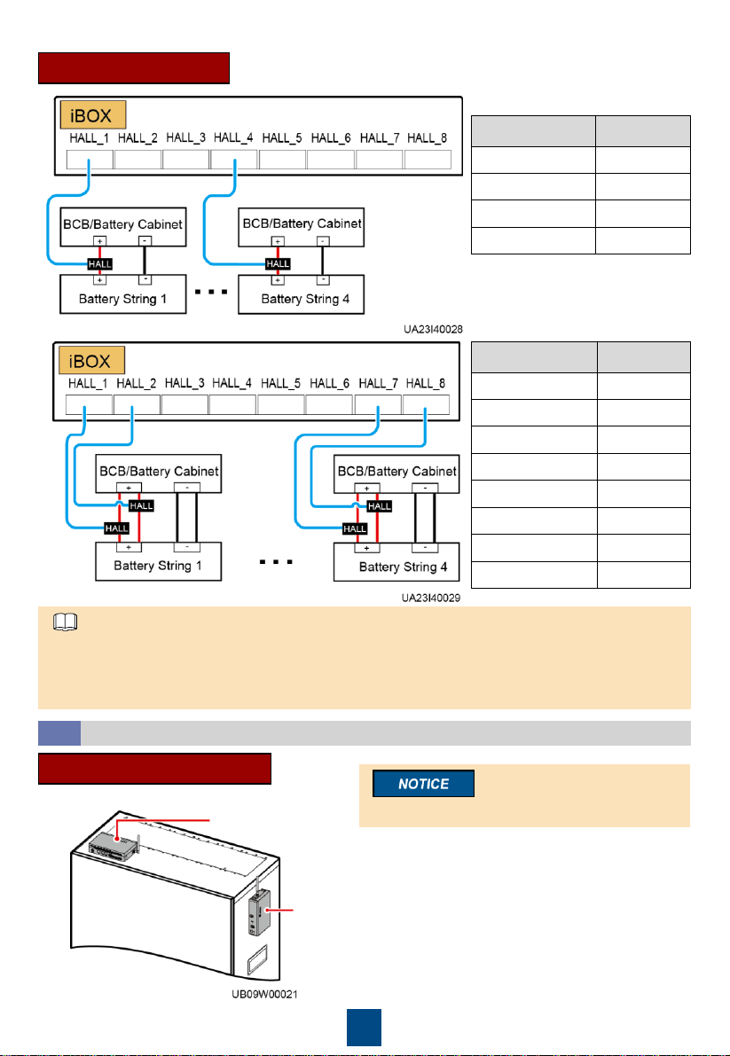
To ensure that the wireless
communication signals are
free from interference, the
distance between the iBOX
and the iBAT should be less
than or equal to 15 m.
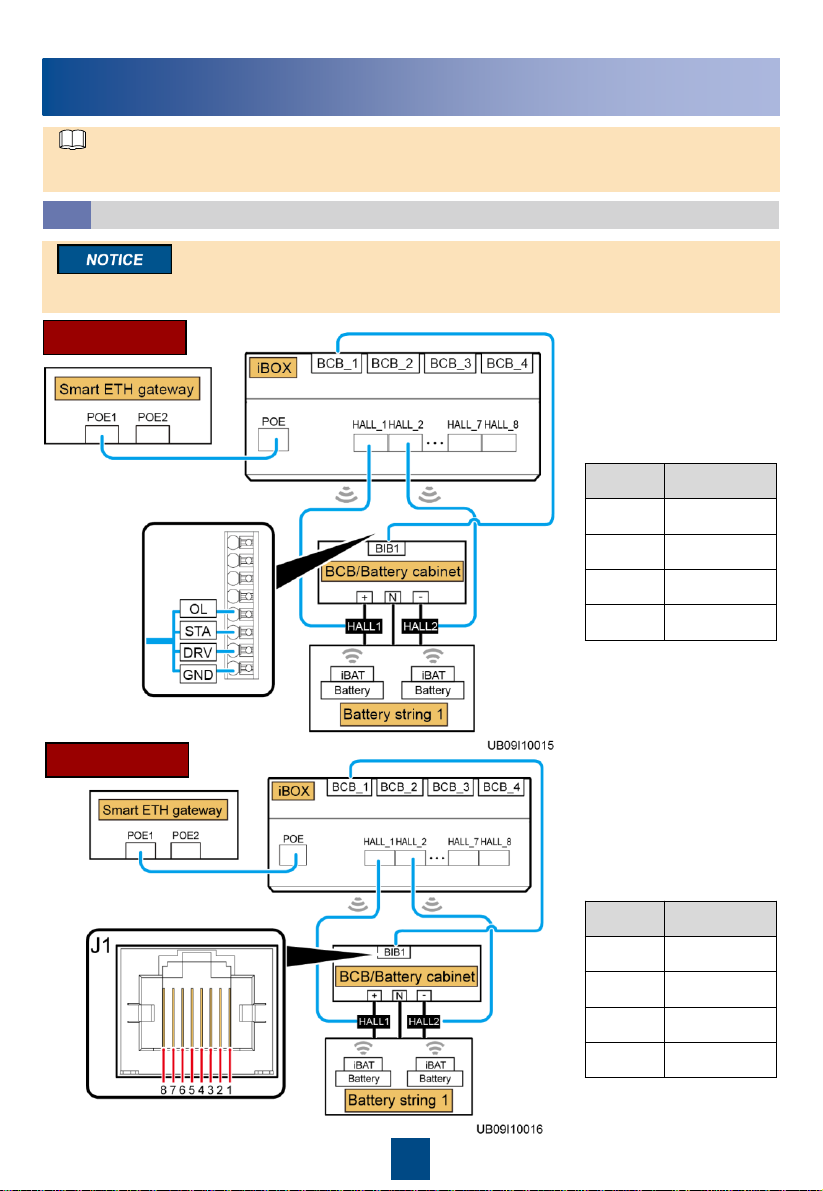
To ensure that the wireless
communication signals
between the iBOX and the
iBAT are free from interference,
remove adjacent side panels
when combining multiple
battery cabinets.
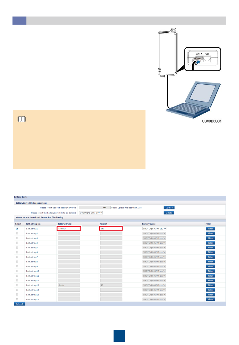
If the LAN switch in the
equipment room provides a
PoE port, no adapter is
required.
•Voltages on the iBAT cables are hazardous. Therefore, wear insulation gloves when performing
operations on the cables.
•The red terminal is positive, and the black terminal is negative. Connect battery terminals correctly.
•After the product is installed, if the battery is not charged for more than 30 days, you are advised
to remove the iBAT from the battery cables.
•Torque: M6: 4–6 N·m M8: 13–15 N·m M10: 15–20 N·m.
•Ensure that terminals are visible when installing the iBAT. If you want to connect iBATs in parallel,
install the iBATs after collecting iBAT SN information and installing cables.
•Do not power on the iBAT before connecting the battery to the system.
•Do not install the iBAT on the exhaust valve of the valve-regulated lead acid (VRLA) battery.