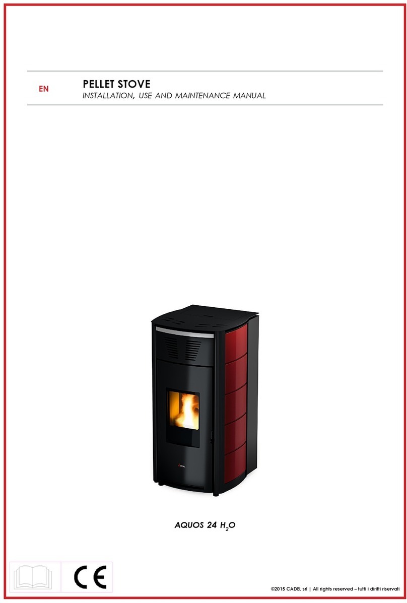
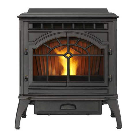
Hudson River Stove Works NIAGARA User manual

Page1 / 25
PLEA
SE
KEEP
THESE
INSTRUCTIONS
FOR
FUTURE
REFERENCE
NIAGARA
PELLET STOVE
OWNER’S
MANUAL
Contact your building or fire officials about restrictions and
Installation inspection requirements in your area.
PLEASE READ THIS ENTIRE MANUAL BEFORE INSTALLATION AND USE OF
THIS PELLET BURNING ROOM HEATER. FAILURE TO FOLLOW THESE
INSTRUCTIONS COULD RESULT IN PROPERTY DAMAGE, BODILY INJURY,
OR EVEN DEATH.
.

Page2 / 25
Introduction
P
ELLET
Q
UALITY
:
Your pellet stove has been designed to burn wood pellets only. Do not use any other
type of fuel, as this will void any warranties stated in this manual.
The performance of your pellet stove is greatly affected by the type and quality of
wood pellets being burned. As the heat output of various quality wood pellets differs,
so will the performance and heat output of the pellet stove.
CAUTION: It is important to select and use only pellets that are dry and free of dirt or any
impurities such as high salt content. Dirty fuel will adversely affect the operation and
performance of the unit and will void the warranty. The Pellet Fuel Industries (P.F.I.) has
established standards for wood pellet manufacturers. We recommend the use of pellets that
meet or exceed these standards. Please use a recommended pellet type.
P.F.I. PELLET STANDARDS:
Fines (fine particles)......1% maximum through a 1/8” screen
Bulk Density..................40 pound per cubic foot minimum
Siz
e..............................1⁄4”
to 5/16” diameter
1⁄2
–
11⁄2”
long
maximum Ash Content..................1% maximum (Premium
grade) ..................3% maximum (Standard
grade) Moisture Content...........8% maximum
Heat Content.................approximately 8200 Btu per pound minimum
ASH: The ash content of the fuel and operation of your stove will directly determine the
frequency of cleaning. The use of high ash fuels may result in the stove needing to be cleaned
daily. A low ash fuel may allow longer intervals between cleaning.
CLINKERING: [clinkers are silica (sand) or other impurities in the fuel that will form a hard
mass during the burning process]. This hard mass will block the airflow through the Burn
Pot Liner and affect the performance of the stove. Any fuel, even approved types, may tend
to clinker. Check the Burn-Pot Liner daily to ensure that the holes are not blocked with
clinkers. If they become blocked, remove the liner (when the unit is cold) and clean/scrape
the clinkers out. Clean the holes with a small pointed object if required. Refer to the
section Routine Cleaning and Maintenance.
PELLET FEED RATES: Due to different fuel densities and sizes, pellet feed rates may vary.
This may require an adjustment to the slider damper setting or to the auger feed trim setting
on low.
Since stove supplier has no control over the quality of pellets that you use, we assume no
liability for your choice in wood pellets.
Store pellets at least 36” (1 m) away from the pellet stove.

Page3 / 25
I
MPORTANT
SAFETY DATA:
Please read this Owner’s Manual before installing or operating your Pellet Stove.
Failure to follow these instructions may result in property damage, bodily injury or
even death. Contact your local building or fire official to obtain a permit and any information
on installation restrictions and inspection requirements for your area.
To prevent the possibility of a fire, ensure that the appliance is properly installed by
adhering to the installation instructions. The dealer will be happy to assist you in obtaining
information with regards to your local building codes and installation restrictions.
Be sure to maintain the structural integrity of the home when passing a vent through walls,
ceilings, or roofs.
The stove’s exhaust system works with negative combustion chamber pressure and a
slightly positive chimney pressure. It is very important to ensure that the exhaust system be
sealed and airtight. The ash pan and viewing door must be locked securely for proper and safe
operation of the pellet stove.
Do not burn with insufficient combustion air. A periodic check is recommended to ensure
proper combustion air is admitted to the combustion chamber. Setting the proper
combustion air is achieved by adjusting the slider damper located on the left side of the stove.
When installing the stove in a mobile home, it must be electrically grounded to the steel
chassis of the home and bolted to the floor. Make sure that the structural integrity of the
home is maintained and all construction meets local building codes.
Minor soot or creosote may accumulate when the stove is operated under incorrect conditions
such as an extremely rich burn (black tipped, lazy orange flames).
If you have any questions with regard to your stove or the above-mentioned information, please
feel free to contact your local dealer for further clarification and comments.
S
AFETY
W
ARNINGS
A
ND
R
ECOMMENDATIONS
:
Caution: Do not connect to any air distribution duct or system.
Do not burn garbage or flammable fluids such as gasoline, naptha or engine
oil.
Unit hot while in operation. Keep children, clothing and furniture
away. Contact may cause skin burns.
FUEL: This pellet stove is designed and approved to only burn wood pellet fuel with up
to 3% ash content. Dirty fuel will adversely affect the operation and performance of the
unit and may void the warranty. Check with your dealer for fuel recommendations.
THE USE OF CORDWOOD IS PROHIBITED.
SOOT: Operation of the stove with insufficient combustion air will result in the formation of
soot which will collect on the glass, the heat exchanger, the exhaust vent system, and may
stain the outside of the house. This is a dangerous situation and is inefficient. Frequently
check your stove and adjust the slider/ damper as needed to ensure proper combustion. See:
“S
LIDER
/D
AMPER
S
ETTING
”.
CLEANING: There will be some build up of fly ash and small amounts of creosote in the
exhaust. This will vary due to the ash content of the fuel used and the operation of the stove.
It is advisable to inspect and clean the exhaust vent semi-annually or every two tons of
pellets.

Page4 / 25
Introduction
ASHES: Disposed ashes should be placed in a metal container. The closed container of ashes should be on
a non-combustible floor on the ground, well away from all combustible materials pending final disposal. If
the ashes are disposed of by burial in soil or otherwise locally dispensed, they should be retained in the
closed container until all cinders have been thoroughly cooled.
ELECTRICAL: The use of a surge protected power bar is recommended. The unit
must be grounded. The grounded electrical cord should be connected to a standard 115 volts (4.5
Amps), 60 hertz electrical outlet, or 1015 volts (4.5 Amps), 60 hertz electrical outlet. Be careful that
the electrical cord is not trapped under the appliance and that it is clear of any hot surfaces or sharp
edges and also must be accessible. If this power cord should become damaged, a replacement power
cord must be purchased from the manufacture or a qualified dealer. The stove’s maximum power
requirement is 520 watts.
GLASS: Do not abuse the glass by striking or slamming the door. Do not attempt to operate the stove
with broken glass. The stove uses ceramic glass. Replacement glass must be purchased from a qualified
dealer. Do not attempt to open the door and clean the glass while the unit is in operation or if glass is
hot. To clean the glass, use a soft cotton cloth and mild window cleaner, gas or wood stove glass cleaner,
or take a damp paper towel and dip into the fly ash. This is a very mild abrasive and will not damage the
glass. DO NOT USE ABRASIVE CLEANERS.
FLAMMABLE LIQUIDS: Never use Flammable Liquid such as gasoline, gasoline-type lantern
fuel, kerosene, charcoal lighter fluid, or similar liquids to start or “freshen up” a fire in the heater.
Keep all such liquids well away from the heater while it is in use.
SMOKE DETECTOR: Smoke detectors should be installed and maintained in the structure
when installing and operating a pellet burning appliance.
OPERATION: The ash pan and door must be closed securely for proper and safe operation of the pellet
stove. Also ensure all gaskets on the door are checked and replaced when necessary.
KEEP ASH PAN FREE OF RAW FUEL.
DO NOT PLACE UNBURNED OR NEW PELLET FUEL IN ASH PAN. A fire in the ash pan may occur.
INSTALLATION: Be sure to maintain the structural integrity of your home when passing a vent through
walls, ceilings, or roofs. It is recommended that the unit be secured into its position in order to avoid any
displacement.
DO NOT INSTALL A FLUE DAMPER IN THE EXHAUST VENTING SYSTEM OF THIS
UNIT.
DO NOT CONNECT THIS UNIT TO A CHIMNEY FLUE SERVING ANOTHER
APPLIANCE.
FRESH AIR: Outside Fresh Air connection is optional. Must be connected to all units installed in Mobile
and “Air Tight Homes” (R2000) or where required by local codes. Consider all large air moving devices
when installing your unit and provide room air accordingly. Limited air for combustion may result in poor
performance, smoking and other side effects of poor combustion.
If you have any questions with regards to your stove or the above-mentioned information, please feel free
to contact your local dealer for further clarification and comments.
SINCE STOVE SUPPLIER HAS NO CONTROL OVER THE INSTALLATION OF YOUR
STOVE, STOVE SUPPLIER GRANTS NO WARRANTY IMPLIED OR STATED FOR THE
INSTALLATION OR MAINTENANCE OF YOUR STOVE. THEREFORE, STOVE SUPPLIER
ASSUMES NO RESPONSIBILITY FOR ANY CONSEQUENTIAL DAMAGE(S).
Page5 / 25
SAVE THIS INSTRUCTION MANUAL FOR FUTURE REFERENCE!
A
UTOMATIC
S
AFETY
F
EATURES
:
Your pellet Stove has the following safety features:
A. The stove will shut off when the fire goes out and the exhaust temperature
drops below 120°F(52°C).
B. The stove has a high temperature safety switch. If the temperature on the hopper reaches
200°F
(93°C), the auger will automatically stop and the stove will shut down when the exhaust
temperature cools. If this happens, call your local dealer to reset the 200°F (93°C) high
limit switch. ALSO FIND THE REASONS WHY THE UNIT OVERHEATED.
C.If the power goes out, the unit will stop running. When the power comes back on, the stove
will not restart unless the exhaust temperature is still above 120°F (52 °C).
Product performance introduction
This Pellet stove is advanced designed and has individual fresh air input and venting system. Negative
pressure burning technology causes high efficiency and little ash during burning. It will shut off automatically
by improper burning or if out of fuel.
Model NIAGARA
Rating input 35000 BTU/H
Heating area 2000 Square Feet
Rating voltage V 115
Rating frequency Hz 60
Rating power W <=150
Hopper LB 55 POUNDS
Venting pipe diameter 3”
Air input pipe diameter 2”
Unit size (wide* depth*high) 22”W x 22 ¼” D x 32 ½”H
Installation

Page6 / 25
Deciding Where to Locate your Pellet Appliance:
When installing this unit on a combustible floor (for example linoleum, hardwood flooring) a non-combustible
hearth pad (3/8” thickness)must be under the unit. The pad must extend at least the width of the appliance
[22” (558 mm)] and at least the depth of the appliance plus 6” (153 mm) in front of the appliance [29 3⁄4” (756
mm)].
Floor Protection
Your pellet stove must be installed on a non-combustible protective floor pad of minimum 3/8” thickness
material or a masonry hearth. The hearth or floor pad must extend a minimum of 6”in front of and from each
side of the stove or to the nearest permitted combustible material if less than 6”.
VENTING

Page7 / 25
PELLET VENT MUST MAINTAIN A MINIMUM 3" CLEARANCE TO ANY COMBUSTIBLE (install vent at
clearances specified by the vent manufacturer).
Must be an approved 3" or 4" Diameter Type "L" or "PL" vent, vented to the outside or connect the vent to a
factory built type "A" chimney using an adaptor; and/or stainless steel chimney liner for masonry fireplace
installations. Use 4" diameter vent if vent or liner height is over 15' or if installation is over 4,000' above sea
level. When passing through a wall, or partition of combustible construction the installation shall conform to
CAN/CSA-B365.OF VENT
MAXIMUM VENTING:
The vent must have a support bracket every 5’ when on the exterior wall. To achieve optimum
performance, keep vent runs as short as possible, especially on horizontal installations. Maximum venting
height is 33'. Maximum horizontal offset is 10'. Use no more than 180° of elbows (two 90' elbows, or two 45'
elbows and one 90' elbow, etc), plus termination.
VENT INSTALLATION:
Termination must exhaust above the air inlet elevation and parallel or above the exhaust output of the pellet
appliance. It is recommended that at least 3' of vertical pipe be installed to create some natural draft. This is
to help prevent the possibility of smoke or odor during the appliance shut down or in the event of a power
outage. Horizontal sections must have a 1/4" rise every 12" of travel if longer than 3'. The pellet vent
connections must be sealed with HI-Temp RTV Silicone and screwed together with at least 3 3/8" long
stainless steel screws. Seal each vent section by injecting a liberal amount of 500°F (260°C) RTV silicone
sealant into the gap. We recommend sealing the outside of the vent connections to permit easier access
when servicing
INGLLETVENT

Page8 / 25
VENTING(CONTINUED)
DO NOT INSTALL A FLUE DAMPER IN THE EXHAUST VENTING SYSTEM OF THIS UNIT. DO NOT
CONNECT THIS UNIT TO A CHIMNEY FLUE SERVING ANOTHER APPLIANCE.
Installation Configurations
HORIZONTAL EXHAUST VENT INSTALLATION
1. Locate your appliance in a location which meets the requirements of this manual and where it
does not interfere with the house framing, wiring, etc..
2. Install a non-combustible hearth pad underneath the unit. This pad should extend at least 6”
(152 mm) in front of the unit, and 6” to the left and right sides.
3. Place the stove approximately 15” (381 mm) away from the interior wall.
4. Locate the center of the exhaust pipe of your unit. This point should then be extended to the
interior wall of your house. Once you have located the center point, on the interior wall, cut a
7” (175 mm) diameter hole through the wall.
5. The next step is to install the wall thimble, refer to the instructions which come with the wall
thimble for this step.
6. Install the appropriate length of exhaust vent pipe into the wall thimble. See step 11 when
determining the correct length of exhaust vent to use.
7. Install the combustion air intake pipe (if applicable). Be sure that the outside air vent has a
proper cap on it to prevent rodents from entering and also is installed where it won’t become
blocked with snow, etc..
8. Connect the exhaust vent pipe to the exhaust outlet of your appliance.
9. Secure all vent joint connections with 3 screws. Seal the exhaust vent joint connections with
high temperature silicone sealant.
10.Push the unit straight back to the interior wall but be sure to maintain the minimum clearances
to combustibles 6” (152 mm) to the back of the unit. Seal the annular space, of the wall
thimble, around the vent pipe with high temperature silicone sealant.
11.The exhaust vent pipe must extend at least 12” (300 mm) out past the exterior wall. Seal the
annular space, of the wall thimble, around the vent pipe with high temperature silicone
sealant.
12.Install a listed horizontal termination cap or if necessary install a 90°elbow and appropriate
length of vertical venting. A listed vertical vent cap is recommended however (if local codes
allow) when the vent terminates several feet above ground level and there are no trees,
plants, etc. within several feet a 45°elbow can be used as a termination. The elbow must be
turned down to prevent rain from entering.

Page9 / 25
Installation Configurations (Cont’d)

Page10 / 25
FREESTANDING INTERIOR VERTICAL INSTALLATION
1. Choose the location for your pellet stove, see item 1 of the Horizontal Exhaust Vent Installation
(page 16) for help in determining the correct location.
2. Install the non-combustible hearth pad.
3. Place your pellet stove on the hearth pad and locate the unit in manner that will leave the
exhaust vent with a minimum of 3” (75 mm) clearance to any combustible wall.
4. Locate the center of the combustion air intake pipe at the back of your unit. Line up the center
with the same spot on your exterior wall and cut a hole 2-1/2” (64 mm) in diameter through the wall.
5. Secure all vent joint connections with 3 screws. Seal the exhaust vent joint connections with
high temperature silicone sealant.
6. Install the optional combustion air intake pipe.
7. Install a tee, with a cleanout, on the exhaust pipe found at the rear of your unit.
8. Install listed vent upward through the ceiling. When you pass through the combustible framing
ensure that the appropriate ceiling is used. You must maintain a minimum 3” (75 mm) clearance
to combustibles and keep any insulation away from the exhaust vent.
9. Extend the exhaust vent through the roof flashing and ensure that the vertical cap is
approximately 36” (900 mm) above the roof.

Page11 / 25
FREESTANDING EXTERIOR VERTICAL INSTALLATION
1. Follow steps 1 – 5 from previous page.
2. Locate the center of the exhaust pipe, at the back of the unit. Line up the center with the same spot on
the exterior wall a cut a 7” (175 mm) diameter hole through the wall.
3. Install the wall thimble, refer to the instructions which come with the wall thimble for this step.
4. Install a listed exhaust vent through the wall, be sure to make sure that 3” (75 mm) clearances to
combustibles are maintained.
5. Secure all vent joint connections with 3 screws. Seal the exhaust vent joint connections with high
temperature silicone sealant.
6. Install a Tee with a cleanout on the end of the exhaust pipe, then install listed venting upward from there.
Be sure to install support brackets every 5’ (1500 mm) to keep the venting straight and secure.
7. Extend the exhaust vent through the roof flashing and ensure that the vertical cap is approximately 36”
(900 mm) above the roof.

Page12 / 25
VENTING: TERMINATION REQUIREMENTS
In determining optimum vent termination, carefully evaluate external conditions especially when
venting directly through a wall. Since you must deal with odors, gases, and fly ash, consider
aesthetics, prevailing winds, distances from air inlets and combustibles, location of adjacent
structures and any code requirements.
1. Exhaust must terminate above combustion air inlet elevation.
2. Do not terminate vent in any enclosed or semi-enclosed area, (i.e. Carports, garage, attic
crawl space, etc.) or any location that can build up a concentration of fumes.
3. Vent surfaces can get hot enough to cause burns if touched by children. Non-combustible
shielding or guards may be required
The type of installation must first be considered before determining the exact location of
the venting termination in relationship to doors, window, cavities or air vents. See figures
4a and 4b below.
A. WITHOUT OUTSIDE AIR CONNECTED TO THE UNIT.
FIGURE4a
4’ (1.2 m) BELOW a door, window, cavity, or air vent
Or
4’ (1.2 m) HORIZONTALLY FROM a door, window, cavity, or air vent
Or
1’ (305 mm) ABOVE a door, window, cavity, or air vent

Page13 / 25
B. WITH OUTSIDE AIR CONNECTED TO THE UNIT.
In this manner the appliance is a Direct Vent Appliance (sealed Combustion System) as listed in
NFPA 211-6.
3.3.3.2 Direct Vent Appliance (Sealed Combustion System Appliance) A system
consisting of an appliance, combustion air and flue gas connections between the
appliance and the outside atmosphere, and a vent cap supplied by the manufacturer, and
constructed so that all the air for combustion is obtained from the outside atmosphere
and all flue gases are discharged to the outside atmosphere.
Special Venting Arrangements are listed in NFPA 211-31
10.7.1.2 The Vent Terminal of a Direct Vent Appliance with an input of 10000 BTU/Hr or
less shall be located at least 6” from any opening into a building, and such an appliance
with an input of over 10000 BTU/Hr, but not over 50000 BTU/Hr shall not be located
less than 9” from any opening through which vent gases could enter a building, and the
vent terminal of such appliance with an input over 50000 BTU/Hr shall be located not
less than 12” from the opening.
Figure 4b

Page14 / 25
THE EXHAUST TERMINATION LOCATION MUST BE AT LEAST:
1’ (305 mm) ABOVE the ground level
7’ (2.1 m) FROM a public walkway
1’(305 mm) FROM The wall penetration point
3’ (915mm) FROM a gas meter/regulator assembly
2’ (610 mm) FROM any adjacent combustibles such as:
Adjacent buildings, fences, protruding parts
of the structure, roof eaves or overhangs,
plants, shrubs, etc.
Note: Certain local code restrictions may apply. Check with Local Officials first before
installing.
VENTING: TERMINATION CLEARANCE REQUIREMENTS SIDE VIEW
(All dimensions show MINIMUM distances)

Page15 / 25
COMBUSTION AIR
WARNING: USE THE AIR INTAKE DAMPER FOR ADJUSTING COMBUSTION INLET
AIR ONLY! OTHER METHODS OF RESTRICTING OR BLOCKING COMBUSTION
INLET AIR IS STRICTLY PROHIBITED!
1. It is recommended that the stove be connected to an outside source of combustion air under
certain conditions (negative pressure). Any flexible metal hose or rigid metal pipe (conduit) must
be connected around (NOT INSIDE) the combustion air inlet tube. Be careful not to pinch or bend
the outside air pipe with too small a radius. Outside Air Pipe may be terminated flush with the
outside wall but should be protected from wind and weather by a hood. Note: The outside air pipe
must terminate above the maximum snow line and below the exhaust vent outlet.
2. Increase the outside air pipe diameter to 3” for runs over ten (10) feet and elevation over
4,000 feet. Note: Long runs should be avoided.
3.Terminate the outside air pipe below the exhaust vent outlet.
4. An open mesh screen should be placed over the outside air pipe opening to prevent birds or
rodents from nesting in the opening. Use an elbow or shield to prevent prevailing winds from
blowing directly into the outside air intake pipe. NOTE: Mesh screen should be no smaller
than one-fourth inch (1/4”) by one-fourth inch (1/4”).
6. In the case of a Custom made sealed fireplace insert shroud, an outside air inlet to the
fireplace cavity is necessary to ensure adequate airflow for combustion.

Page16 / 25
Electrical:
The unit must be grounded. The grounded electrical cord should be connected to a standard 115V,
60Hz(4.5 Amps), (115 volts (4.5 Amps), 60 hertz) electrical outlet. Be careful that the electrical cord is
not trapped under the appliance and that it is clear of any hot surfaces or sharp edges and also must be
accessible. If this power cord should become damaged, a replacement power cord must be purchased
from the manufacturer or a qualified dealer.
Electrical figure

Page17 / 25
MOBILE HOME INSTALLATION
Mobile home installation should be done in accordance with the Manufactured Home and Safety
Standard (HUD), CFR 3280, Part 24.
In order for this unit to be installed in a mobile home the following criteria must be met:
•The unit must be secured to the floor using lag bolts in the holes provided in the pedestal
base.
•Ensure that the unit is permanently electrically grounded to the chassis of your home.
IT IS MANDATORY TO TAKE THE COMBUSTION AIR FROM THE OUTSIDE WHEN INSTALLING
THIS UNIT IN AIR TIGHT OR MANUFACTURED/MOBILE HOMES.
CAUTION:
THE STRUCTURAL INTEGRITY OF THE MANUFACTURED HOME FLOOR, WALL, AND
CEILING/ROOF MUST BE MAINTIANED.
WARNING: DO NOT MAKE COMPROMISES DURING INSTALLATION. FOLLOW
ALL CLEARANCE REQUIREMENTS AND CHIMNEY INSTRUCTIONS CARFULLY.
FAILURE TO FOLLOW THESE REQUIREMENTS MAY RESULT IN PROPERTY
DAMAGE, BODILY INJURY, OR EVEN DEATH.
WARNING:
DO NOT INSTALL IN A BEDROOM.
Maintain an effective vapor barrier at location where vent exits the structure.
Check any other local building codes or other codes that may apply.
Follow Vent manufacturer’s installation directions and observe all listed clearances to
combustibles.

Page18 / 25
Operation Instructions_______________
1. The first ignition
Some odors may be given off during the first few hours of burning during initial break-in.
These odors are normal and not harmful. However, ventilating the room until the odors disappear is
recommended. The stove will become HOT while in operation. Keep children, clothing and furniture away
from all stove surfaces. WARNING: DIRECT CONTACT WITH THE STOVE WHILE OPERATING MAY
CAUSE SKIN BURNS.
To avoid the possibility of smoke and/or sparks entering the room always keep firebox and de ashing doors
closed whenever the stove is operating.
Please connect the power and put wood pellet fuel (max. 20kg) into the hopper.
2. Start and operation
To Start up a Cold Stove
Press and release the On/Off button. The green light above the On/Off button will flash to indicate that the start
up cycle has started. The light above the Auger button will turn on, intermittently, indicating the activation of the
auger which is feeding the pellets into the burn pot. At this time the electric igniter is activated. The igniter
takes a few minutes to heat up enough to ignite the pellets in the burn pot. This may take as little as 3 minutes or
as much as 8 minutes. If no flames appear prior to 15 minutes the stove will shut down and will need to
be turned back on again.
Once the flame has been established, the start up cycle will end, this takes between 10 - 15 minutes. At this
point, if the stove is in the manual mode, it will default to the lowest heat level setting. If the stove is in either the
AUTO or T-STAT mode the heat output will vary in accordance with the commands from the thermostat.
To Start up a Hot Stove
If the stove is warm at re-start, the On/Off button must be pressed down and held for 2 seconds or more until the
Heat Level light is lit.

Page19 / 25
When first starting a new pellet stove, or when you completely empty the hopper of pellets, you can press and
hold the AUGER button to get the pellets into the burn pot quicker. See AUGER button description on page 10.
The convection air flow will change in accordance with the heat setting. Convection air flow is at maximum when
the heat setting is at maximum. Air flow will be at a minimum when the heat setting is at a minimum. If the user
wishes to turn the convection fan on maximum, at any heat setting, they may do so by pressing the FAN button.
If the flame goes out, or the heat output is too high on minimum heat level setting, use the AUGER TRIM button to
make adjustments. See the AUGER TRIM button description on page 11.
To Shutdown Stove
Turn off the unit by pressing the On/Off button. The stove will enter the shutdown cycle where the pellets will
stop feeding to allow the fuel in the burn pot to be used up. The exhaust blower and convection fan will continue
to operate until the flames are out and the unit has cooled down. Once this has been accomplished the stove
will shut down completely.
In the AUTO mode the turning the thermostat all the way down can also be used to turn off the stove.
DO NOT TURN OFF THE UNIT BY DISCONNECTING THE ELECTRICAL POWER TO THE UNIT. THIS WILL
CAUSE THE UNIT TO MISS THE PROPER SHUTDOWN CYCLE, CAUSING THE RELEASE OF SMOKE INTO
THE HOUSE AND OVERHEATINGOF THE STOVE.
Safety
a. The stove will power off and the fire will be put out within 25min when the auger motor stops.
b. The stove will power off and the fire will be put out within 30min when the convection blower stops.
c. Auger motor stops feeding when thermodisc T3≥93˚C. When the T3<93˚C, the auger motor feeds again,
the stove will keep working.
IF YOU HAVE A FIRE:
•Call the fire department immediately.
•If all the stovepipe joints are tight and no other appliance is connected to the same flue, close all
openings, and draft controls if you have an airtight stove. Close the stovepipe damper in a non
airtight stove.
•If you have a leaky stove, you may have to wait for the fire to burn out.
•Get everyone out of the house, and put them to work watching for sparks or signs of fire on the roof
or nearby. One adult should stay in the house to check the attic and upper floors for signs of fire.
•Discharge a class ABC dry chemical fire extinguisher or throw baking soda into the stove if the
chimney is not sound or there is a danger of the house or surroundings catching on fire. The
chemical travels up the chimney and often extinguishes the flame. Special fire extinguishers are
also available for stove and chimney fires. They give off intense smoke and smother the fire.
•Throwing water in a stove will cause the metal to warp, but if it’s a choice between the house or the
stove, use water.
•Make sure the chimney is inspected after a fire. A chimney fire can cause deterioration of metal or
cause masonry to weaken.

Page20 / 25
Maintenance
Daily Maintenance
ALL Maintenance should be done when the stove is shut off and cold.
1. Check Grate and Shaker Plate to determine if holes are plugged.
a. Clean as needed.
b. Open the firebox door slowly to prevent drawing ash or odors into the room.
c. Use the “scraper” provided to move the burning pellets to one side of the grate, leaving the ash in the
bottom of the grate.
d. Rake the ash & clinkers out over the grate into the ash pan.
e. Rake the burning pellets across the bottom of the grate.
f. Close the door.
CAUTION: NEVER ADD FIRE STARTER TO A HOT STOVE.
2. Remove ash buildup under the grate bottom daily or as frequently as needed. Clean the ashes out from
under the burn pot by pulling the Ash Cleanout Rod in and out several times
CAUTION: The Ash Cleanout Rod must be pushed all the way in during operation of the
unit. Failure to keep this area clean could result in a safety hazard.
3. Check ash pan to determine emptying frequency needed. NOTE: Do not use a vacuum cleaner for this
purpose. Hot coals may cause your vacuum filter to catch fire. Place ashes in a metal container with a tight
fitting lid. The closed container of ashes should be placed on a noncombustible floor or on the ground, well
away from all combustible materials, pending final disposal. If the ashes are disposed of by burial in soil or
otherwise locally dispersed, they should be retained in the closed container for at least two days until all
cinders have thoroughly cooled.
4.Once or twice daily pull the Heat Exchange Tube Scraper, out and back to clean heat exchange tubes.
Failure to operate the tube scraper daily may result in poor combustion and loss of heat output. This should
be done when the stove is cool or operating on the low temperature setting.
5.The rate of burn and the quality of fuel will determine how often the window needs cleaning. Prolonged
burning at a slow burn rate will result in the need for more frequent window cleaning. Burning poor fuel also
increases the need to clean the window. Cooling the stove and wiping the window daily with a cloth or paper
towel will normally keep the window from accumulating difficult to clean residue. Use of a glass cleaner
ONLY permitted when the stove is cold. Tip: Dip the damp towel in the ashes to remove stubborn buildup on
the glass. NEVER USE ABRASIVE CLEANER ON GLASS SURFACES.
CAUTION: Do not slam the door. Do not operate the stove with a broken or cracked
glass. Replace only with heat resistant ceramic glass supplied by the manufacturer.
6. Burn the stove at the HI fuel setting for at least 20 to 30 minutes each day. This helps keep the window,
ceraboard and firebox area clean. A daily high burn also aids in maintaining the overall efficiency and
performance of the stove.
Table of contents
Other Hudson River Stove Works Pellet Stove manuals
Popular Pellet Stove manuals by other brands

EdilKamin
EdilKamin CALGARY Installation, use and maintenance

Extraflame
Extraflame LUCREZIA IDRO LCD instruction manual

monolith
monolith Extra installation manual

kozy heat
kozy heat Woodland WLD-P installation manual

Petric
Petric PP27A-G3 Instructions for use, maintenance and installation

CASTLE
CASTLE Serenity Pellet Stove Operator's manual