Humidity Source ElectroVap RTH User manual

Humidity Source
Quality, Selection, Support
Electric Resistance
Steam Humidifier

PERFORMANCE AND FEATURES
- Full range : (11-220 lbs/hr) output
- Works with any type of water
- Microprocessor control with
easy-to-read backlit display
- Self diagnostic with default display
- Proportional control or ON/OFF
- Accuracy +/- 2 % RH
- Accept all common modulating signals
- Duct pressure up to 10.03" H2O
- Combined capacity up to 1543 lbs/hr
- Anti foaming control
- Integral humidity controller or
external control
- High flow cooling fan preventing
overheating
- Automatic drain after inactivity
- Fast drain (max. 15 sec)
- Manual drain possible
- Inlet valve with internal filter
- Outlet valve with large orifice for
easy-scale elimination
- Self cleaning level control probe
- Option to maintain tank water at
(175°F)
- CE marked
- CSA-c-us listed
EASY MAINTENANCE
- Permanent stainless steel tank
- Self cleaning INCOLOY elements
repelling scale
- Pivoting tank with intermediary
position allowing easy maintenance
- Cooling cycle before maintenance
conserves downtime
- Frontal access to all components
- Display message to point out
maintenance to do
OPTIONS
- Remote information board
- RS 485 interface with possibility
to give number of units for easy
BMS control
- High level safety humidistat and
sensor
- Steam and condensate hoses
- Steam pipe for standard or
short distance absorption

Supply V 460V—3ph 480V—3ph 575V—3ph 600V—3ph
RTH Model lbs/hr A Kw lbs/hr A Kw Lls/hr A Kw lbs/hr A Kw
7 15 7 5 17 7 6 15 5 5 17 6 6 1
15 36
16 12 40 16 14 36 13 13 40 13 14
1
20 52 22 18 56 23 19 52 18 18 56 19 19 1
30 73
31 25 79 33 27 73 25 25 79 26 27
1
40 88 38 30 96 40 33 88 30 30 96 32 33 1
50 109 47 37 119 49 41 109 38 38 119 39 41 1
60 124 54 43 135 56 47 124 43 43 136 45 47 2
70 145 63 50 158 66 545 145 50 50 158 53 54 2
80 176 76 60 192 79 66 176 61 61 192 64 66 2
90 197 85 68 215 89 74 197 68 68 215 71 74 2
100 218 94 75 237 98 82 218 75 75 238 79 82 2
No. of
Tanks
Supply V 230V—1ph 208V—3ph 230V—3ph
RTH Model lbs/hr A Kw lbs/hr A Kw lbs/hr A Kw
5 13 20 5 1
8 18
28 6 14 13 5 17 14 6
1
18 32 31 11 40 34 14 1
25 46 44 16 56 49 19
1
36 65 62 22 79 68 27 2
44 78 75 27 96 83 33
2
51 92 88 32 112 97 39 2
62 111 106 38 135
11
7 47 2
No. of
Tanks
Number of Tanks Dimension (L x H x W) Net Weight lbs. Full Weight lbs.
1 32 x 30 x 14 77 143
2 48 x 30 x 14 143 268
Simple Maintenance !
Disconnect the steam hose and remove
it from the cabinet. Tilt tank forward to
first stop.
Unlock the tank cap and set electrode
elements on top of the humidifier upside
down. (No need to disconnect the wiring)
The fast draining followed by the cool
cycle causes the electrode scale to fall off.
Adjust the flexible scale collection bag on the tank. Swing the tank completely down, all the
scale will fall into the collection bag.
Humidity Source, LLC
90 Dayton Ave. Suite 58 Passaic, New Jersey 07055
TEL 973-916-1001 FAX: 973-916-0770

ElectroVapRTH
Contents
Unit wall installation
Dimensions 3
Wall mounting 4-5
Water connection 6
Steamoutput 7
Condensate draining 8
Steam distribution pipe 9
Steam pipe positioning 10-11
Absorption distance 12
Electrical installation
Electrical wiring 13-15
Connecting options 16
Software assistant
Start up 17-18
Humidifier configuration menu 19-20
Humidifier status menu 21
Changing unit configuration 22-23
Alerts and warnings 24
Maintenance
Tank maintenance 25-26
Valves maintenance 27
INSTALLATION MANUAL

ElectroVapRTH
Dimensions
Unit mounting
Overall
dimensions (in) Steam ou-
tlet (in)
Weight
empty
(lbs)
Weight
full (lbs)
A 31.5 1 12.6 a 3.0 77 143
B 29.6
C 13.4
Drain ou-
tlet (in)
RTH 5 to 50
Overall
dimension (in) Steam ou-
tlet (in)
Weight
empty
(lbs)
Weight
full (lbs)
A 47.3 1 10.0 a 3.0 110 265
B 29.6 2 18.4
C 13.4
Drain outlet
(in)
RTH 60 to 100
A
a
1
C
B
a
1
B
A C
2
3

ElectroVapRTH
Unit Wall Installation
UNIT MOUNTING
Unpack the unit and check for any damage.
A drilling template is supplied with the
packing : make sure to locate it before
throwing away the packing material.
Damage to packing and/or unit must be
reported immediately to the trucker. Save all
packing materials for their inspector.
Provide free space all around the unit, 3 to 3
1/2 ft. from the floor to the bottom of the
humidifier and at least 3 ft. above and 2 ft. on
the right hand side for allowing easy access for
maintenance.
Position the supplied drilling template against
the mounting wall and mark the mounting holes.
Drill the 7 (seven) holes and insert screws and
bolts appropriate for support (3 across top and
4 behind tank. ).
Install the 3 (three) upper screws allowing about
1/2 in. for hanging the cabinet. Hang the
cabinet and tighten the upper screws for
securing the mounting.
Loosen the release knob (1) a little, tip the
stainless steel tank (2) down until the steel
restraining cord is tight (3).
Disconnect the water level wires (4).
2
1
3
4
Drainin
g
hose
2
4
3
4

ElectroVapRTH
Unit Wall Installation
UNIT MOUNTING
(continued)
Unlock the tank cover and lay it on the top of the
humidifier upside down.
Release the steel restraining cord while holding
the tank.
Let the tank gently tip all the way down.
Insert lower screws at 4, 5, 6 & 7 then tighten all
seven mounting screws.
Once all the screws are tightened, you can :
Tip the tank back to intermediate position and
attach the steel restraining cord.
Replace the tank cover and secure the 4
fasteners.
Reconnect the high water level wires.
Set the humidifier tank back to upright position
and tighten tank release knob 1 (see page 4). 4,5,6,7
5

ElectroVapRTH
Water Connection
Unit mounting
A fresh cold water service should be used to supply the unit.
The water pressure should be between 15 and 90 psi and
should not exceed 100°F in temperature.
The water supply connection is through the bottom of the
unit. The humidifier is delivered with a 20 in. long water inlet
hose, with a 3/4 in. threaded female connector for the cold
water supply.
A manual shut-off valve and a check valve (not
included) should be located on the cold water service
connection to the unit.
Information about the water quality :
Chloride concentration < 75 mg/l
Phosphate concentration < 5 mg/l
Low concentration of CO2.
Organic elements in low concentration
Tap water or raw water
The water total desolved solids (TDS) may be up to 23
gr/gal (400 ppm). Check with the local water company. For
tank maintenance, refer to the maintenance page.
Softened water
The water TDS can be from 3.5 gr/gal (60 ppm) up.
Demineralized water
The RTH humidifier can run with demineralized water of
30 µS minimum (0.7 gr/gal or 12 ppm).
Water inlet hose.
Shut-off Valve
w/check valve.
Water supply service.
6

ElectroVapRTH
Steam Output
Installation
Use only high quality, low pressure steam
hose which is able to withstand steam
humidifier temperatures.
The steam hose alone may be used for
distances up to 6 ft. If the distance from the
humidifier to the duct is greater than 6ft.,
insulated rigid copper tube should be used,
with sections of steam hose for connectors.
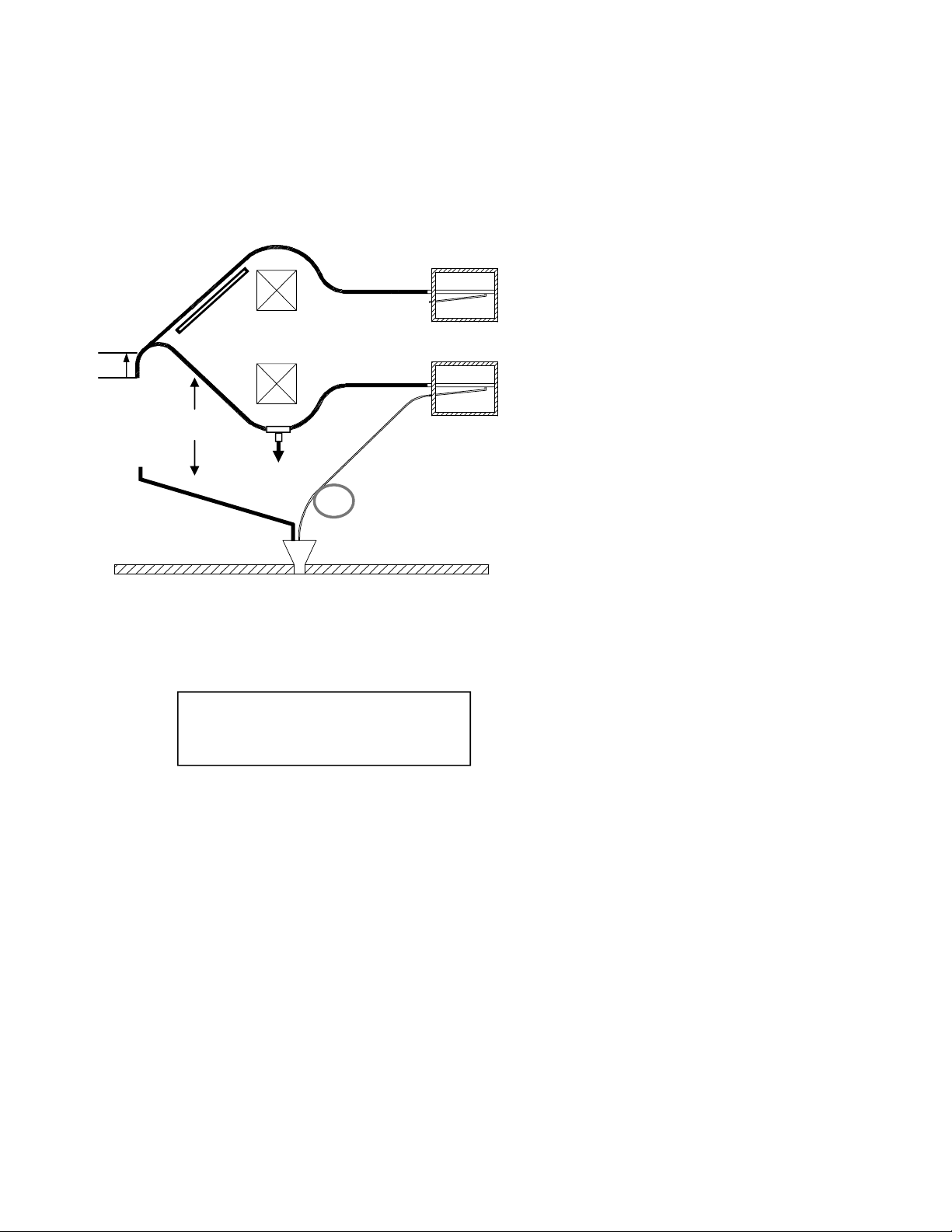
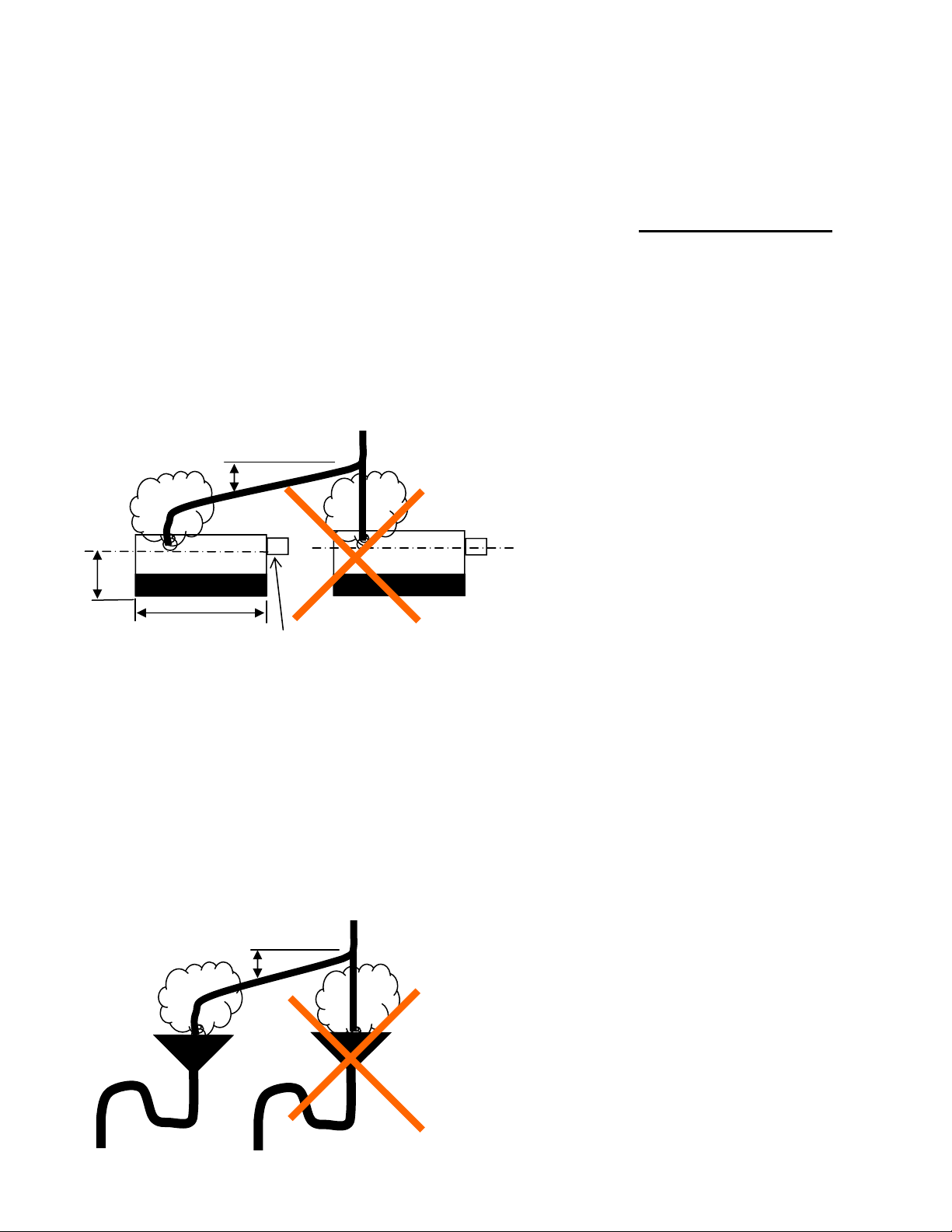
All steam lines must be pitched so that
condensate which forms in the lines will be
drained back to the steam generator or to a
separator & trap in the steam line.
a. Provide vertical rise at least 20 in. before
bending the hose to horizontal.
b. The steam hose should be rigidly suported
to promote rapid draining.
c. Steam hose (radius of bend should be 30
in. Minimum.)
d. Duct work.
e. Obstacle.
f. A condensate separator and trap is needed
at this point to drain condensate.
g. 8 mm condensate hose. Fill the
condensate hose trap with water before
starting the humidifier to prevent steam
from escaping.
h. Humidifier height (see page 3. )
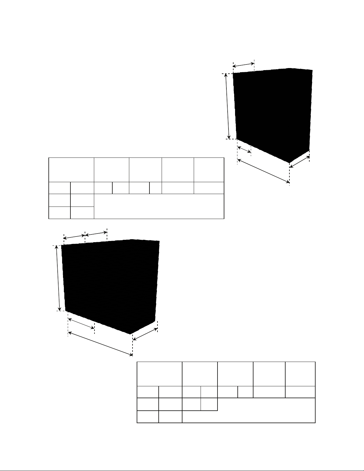
Number of steam outlets:
RTH 5 to 20 = 1 outlet 60mm ( 2.4 ‘’)
Reducer may be used (see page 9)
RTH 30 to 50 = 1 outlet 60mm (2.4’’)
RTH 60 to 100 = 2 outlets 60mm (2.4’’)
The RTH humidifier can work with duct
pressure up to 10’’ of water column.
b
h
g
f
To Drain
c
a
d
e
Steam Hose Sizes
40mm (1.6 in.) Dia. for RTH 5 to 20
60mm (2.4 in.) Dia. for RTH 30 to 100
7

ElectroVapRTH
Condensate Draining
Installation
Drain Connections
10°
1 inch min. dia.
18 in.
12 in.
Caution !
Steam Vapor
Use high quality steam hose capable of
steam humidifier temperatures up to
212 deg F.
RTH 5 to 100: 3 ft. of 40mm hose with 3
hose clamps provided.
This hose is designed for connecting the
humidifier to the drain. Periodic
replacement may be recommended.
If rigid piping is used, use copper or heat
resistant PVC material (212°F ).
The drain hose must be free from any
obstacle particularly when it comes to
connecting several units.
It is recommended the piping be offset
rom the underside of the unit as shown.
This will prevent any steam and/or
condensation from rising directly into the
cabinet.
A funnel can be used as well provided it is
offset from the underside of the humidifier
and that a drain trap is made as per the
diameter of the draining hose.
Important : keep a minimum pitch of 10°
Caution !
Steam Vapor 10°
3 inch min.
8

ElectroVapRTH
Steam Distribution
Pipe
Installation
2 in. L1
1.6 in. o
r
2.4 in.
Stea
m
d
i
spe
r
s
i
o
n
p
i
pe
DL
Steam from the humidifier enters the duct
or an air handling unit via a steam
distribution pipe. For optimum absorption of
the steam, select the longest possible pipe.
Use multiple pipes if neccessary.
HumidiPack ®
The HumidiPack ® is a pre-fabricated
steam humidifier panel made to suit the
duct or AHU conditions and ready to be
installed.
It allows for absorption distances as short
as 2 ft.
8mm
Air flow
HumidiPack ®
L1
Steam Distribution
Tube Model for :
RTH 5 to 20 In.
L4029 12
L4059 24
L4079 31
L40100 39
L40125 50
L40150 59
L1
Steam Distribution
Tube Model for :
RTH 30 to 90 in.
DL-1 10
DL-1,5 16
DL-2 22
DL-3 34
DL-4 46
DL-5 58
DL-6 70
DL-7 82
DL-8 94
DL-9 106
DL-10 118
A 2.4 in. to 1.6 in. reducer is
used with distribution pipe of
1.6 in. for ElectroVap RTH 5
to 20.
9

ElectroVapRTH
SteamPipePositioning
Installation
Install the distribution pipe on the duct with 4
scews.
A minimum distance of 12 in. between the
center of the steam distribution pipe and the
top of the duct should be alllowed. Where
the distribution pipe is installed at an angle
of between 30° and 45°, this may be
reduced to 6 in.
Where the application requires two
distribution pipes, the above-mentioned
recommendations should be observed
keeping a minimum space of 6 in. between
the pipes.
(d) is the minimum distance between the
distribution pipe and any obstacle within the
duct (see table on page 12).
Where a steam pipe is installed after a bend,
it should be positioned in the main air flow.
In vertical ducts where the air flow is upward
or downwards, the steam distribution pipe
should be mounted at an angle of 15° from
vertical
6 in.
12 in.
10

ElectroVapRTH
SteamPi
p
ePositionin
g
Installation Pipe under humififer RTH 5 to 50
Condensate
Pipe above humidifier RTH 5 to 50
Condensate
Air
Flow
Condensate
Air
Flow
HumidiPack ® insertion in duct RTH 60 to 100
Insertion in duct RTH 60 to 100
12 in. min.
8 in. min.
Trap must be full of water before starting the unit
Condensate
Drainin
g
HmidiPack ®insertion in duct RTH 5 to 50
11

ElectroVapRTH
Absorption
Distance
Installation
In order to determine the absorption
distance, this table can be used if you have
the following :
RH1 = relative humidity of the air before
humidification.
RH2 = relative humidity of the air after
humidification in %.
Delta RH = difference between RH1 &
RH2
How to use the table
Determine the difference between the
relative humidity (RH2) after the
humidification and the relative humidity
(RH1) before humidification. The
intersection between the delta RH value
and RH2 gives the evaporation distance in
inches.
.
The drawings show the distance (D) in
inches that should be allowed between the
distribution pipe and the first obstacle.
If the required distance is not available, it is
possible to install two pipes in parallel to give
better steam distribution.
A multi-steam distribution panel may be used
for short absorption distances. See catalog.
A high limit humidistat should be installed
to prevent excessive humidity levels in the
duct.
Note : The absorption distances given in
the table are for temperatures between
50°F and 78°F.
If accurate values cannot be determined or
estimated, a distance of 6.5 ft. should be
used as a safe minimum distance between
distribution pipes & any obstruction.
Absorbing Distance In Inches (D)
Delta RH %(RH2—RH1)
RH2
in % 5 10 15 20 30 40 50 60 75 90
40 12 16 20 20 28 32
50 16 20 20 28 32 36 40
60 16 20 24 28 36 40 43 48
70 20 24 28 36 40 48 50 60
80 20 28 36 40 48 55 63 71 80
85 24 32 40 40 55 63 71 80 91
90 28 40 48 55 60 80 90 100 110 120
95 40 55 67 80 100 114 126 140 154 170
Before/after filters
Controls and sensors
Elbows and branches
Duct transistions
Before or after fan
12

ElectroVapRTH
Electrical Wiring Installation
Power su
pp
l
y
connection
Beware ! Before connecting the power supply, make sure that the main breaker is the same
capacity as the the unit requirements.
Ground terminals
Power wire and control
circuit connecting terminals
13

ElectroVapRTH
Electrical Wiring
Installation
Voir chapitre
raccordemen
régulation
ts
ion pour
ance
(option)
e 2A
Caisson de
ventilat
l'ambi
Protection
externe
command
Protection
externe
puissance
COMMANDE
230V VAC
2x
50
TER
-60Hz +
RE
PUISSANCE
3x400V VAC
50-60Hz
2
1
L
N
PE
L2 L3
L1
6T3
14 NO
A2
4 T2
K1
1/L1
2 T1
S2
2/T1 1/L1
A2
5 L3
13 NO
3 L2
A1
4/A2-
1 L1
3/A1+ 4/A2-
4
2/T1
S1
3
3/A1+
Voir chapitre
nts
ion pour
ance
(option)
raccordeme
régulation
Caisson de
ventilat
l'ambi
Protection
externe
commande 2A
Protection
externe
puissance
PUISS
400V
50-60H
ANCE
VAC
z
3x
COMMANDE
2x230V VAC
50-60Hz +
TERRE
3/A1+
2/T1
PE
2
1
L
N
L3
L1 L2
14 NO
A2
4 T2
6T3
2 T1
K2
14 NO
A2
6T3
4 T2
K1
1/L1
2 T1
S4
A2
13 NO
A1
3 L2
5 L3
1 L1
A2
13 NO
5 L3
3 L2
A1
4/A2-
1 L1
S3
1/L1 2/T1 1/L1 1/L1
2/T1
S2
2/T1
S1
4/A2- 3/A1+ 4/A2- 4/A2-
3/A1+ 3/A1+
34
RTH 5
RTH 10 to 50
RTH 60 to 100
Blower pack
(if used)
Voir chapitre
raccordemen
régulation ts
r
e
(option)
commande 2A
Caisson de
ventilation pou
l'ambianc
Protection
externe
Protection
externe
puissance
L2
1
PE
NL2L1
14 NO
A2 A2
13 NO
6T3
4 T2
K1
2 T1
1/L1 2/T1
S1
34
5 L3
3 L2
A1
1 L1
4/A2- 3/A1+
COMMANDE
2x230V VAC
50-60Hz +
TERRE
AC
PUISSANCE
2x230V V
50-60Hz
Blower pack
(if used)
Power
Circuit-
Single
Phase
External
power
protection
2 A external
power control
Control
Circuit
230-1-60
See operating
control
connections
Blower pack
(if used)
Control
Circuit
230-1-60
Control
Circuit
230-1-60
2 A External
Control Circuit
Fusing
See
Operating
control
Connections
2 A External
Control
Circuit
Fusing
See
Operating
Control
Connecrtions
Power Circuit
Three Phase
14
F
u
s
e
F
u
s
e
Power Circuit
Three Phase NOTE: External power protection
( fuse or circuit breaker) must be
provided in accordance with all
national and local codes.

ElectroVapRTH
Control Connection
Installation
Dip Switch S1:
To select the control signal
(see above configuration
drawings)
RJ45 connector : provides
for a computer connection X6 connector: 21-22-23-24-25
X5 connector: 18-19-20
Main board # 500101/03
15

ElectroVapRTH
Connecting Options
Electrical installation
Remote information board
30
On peut ainsi choisir un contact NO ou NF simplement en
changeant la position du connecteur.
X21
X20
X22
32
31
30
36
33
NO
35
3837
34
NF Ex.
NO
32
31
30
X20
NF
32
31
X20
Board # 500400/03
A NO or NC contact can be selected by simply
chan
g
in
g
the
p
osition of the connector.
Connector X22 (36-37-38): steam production
information dry contact
Connector X21 (33-34-35): general fault
information dry contact
Connector X20 (30-31-32): cylinder
maintenance information dry contact
NC
Option - RS485 or RS422 or RS232 interface
Main board
Remote information board
N
C
CHARACTERISTICS:
RS485 : 2 wires half duplex (+GND) Max. distance 4000 ft.
RS422 : 4 wires half duplex (+GND) Max. distance 4000 ft.
RS232 : 2 wires half duplex (+GND) Max. distance 800 ft.
Bias : 620 Ohms pull-up & pull-down (jumpers selectable)
Termination : 120 Ohms (jumper selectable)
Protocol : JBUS or MODBUS (data asyncronos of 8 bits, no
parity bit, 1 stop bit, CRC) - Speed : 1200, 2400, 4800, 9600
baud.
Mounting : on unit Din rail.
Dimensions : 3.7 x 2 in.
Board # 500800/01
16

ElectroVapRTH
Front panel identification
Softwareassistant
Power Li
g
ht
ON/OFF Switch
Manual Drain
Steam Production Li
g
ht
Scroll Down
Scroll Up
Select Menu
Alphanumerical Display
17

ElectroVapRTH
RTH Startup
Software assistant
STARTUP
1After completion of the installation inspection,
turn on the water supply to the unit
2Switch on the main power supply.
3The power lamp should be illuminated.
4Switch the power supply I/O switch on I. The
display will default to show the rate of steam
produced.
Display operation :
1Pressing the SELECT button repeatedly
will rotate between the three main menus.
2Enter the desired menu by pressing the up
or down button.
The unit provides three menus :
HUMIDIFIER CONFIGURATION
This menu provides information only on the setup
of the humidifier. No parameters can be changed
from within this menu.
HUMIDIFIER STATUS
This menu provides information on the operating
status of the humidifier. No parameters can be
changed from within this menu.
CHANGING UNIT CONFIGURATION
This menu allows adjustments to the setup or
operating parameters of the unit. Access to the
changing humidifier configuration menu is
protected by an access code to guard against
unauthorized access. See Configuring the unit .
18
This manual suits for next models
19
Table of contents
Other Humidity Source Humidifier manuals