Hunt Engineering HEP40E User manual

HUNT ENGINEERING
Chestnut Court, Burton Row,
Brent Knoll, Somerset, TA9 4BP, UK
Tel: (+44) (0)1278 760188,
Fax: (+44) (0)1278 760199,
Email: sale[email protected]
URL: http://www.hunteng.co.uk
We are a
committed
member of the
Texas Instruments
3rd party
programme
HUNT ENGINEERING
HEP40E
TIM Motherboard for AT BUS
USER MANUAL
Hardware Rev A
Document Rev C
T. Hollis 29/6/99
For Sales and Support in North America Please Contact Our Strategic Partner:
Traquair Data Systems Inc, 114 Sheldon Road, Ithaca, NY 14850 USA
Tel 607 266 6000, Fax 607 266 8221
Email Traquair@traquair.com, URL http://www.traquair.com
For Sales and Support in Other Areas Please Contact Your Local Reseller.

2 HUNT ENGINEERING HEP40E USER MANUAL
COPYRIGHT
This documentation and the product it is supplied with are Copyright HUNT
ENGINEERING 1999. All rights reserved. HUNT ENGINEERING maintains a policy
of continual product development and hence reserves the right to change product
specification without prior warning.
WARRANTIES LIABILITY and INDEMNITIES
HUNT ENGINEERING warrants the hardware to be free from defects in the material
and workmanship for 12 months from the date of purchase. Product returned under the
terms of the warranty must be returned carriage paid to the main offices of HUNT
ENGINEERING situated at BRENT KNOLL Somerset UK, the product will be repaired
or replaced at the discretion of HUNT ENGINEERING.
Exclusions - If HUNT ENGINEERING decides that there is any evidence of
electrical or mechanical abuse to the hardware, then the customer shall have no
recourse to HUNT ENGINEERING or its agents. In such circumstances HUNT
ENGINEERING may at its discretion offer to repair the hardware and charge for
that repair.
Limitations of Liability - HUNT ENGINEERING makes no warranty as to the fitness
of the product for any particular purpose. In no event shall HUNT
ENGINEERING’S liability related to the product exceed the purchase fee actually
paid by you for the product. Neither HUNT ENGINEERING nor its suppliers
shall in any event be liable for any indirect, consequential or financial damages
caused by the delivery, use or performance of this product.
Because some states do not allow the exclusion or limitation of incidental or consequential
damages or limitation on how long an implied warranty lasts, the above limitations may not
apply to you.
TECHNICAL SUPPORT
Technical support for HUNT ENGINEERING products should first be obtained
contacting your local supplier, if you are unsure of details please refer to
www.hunteng.co.uk for the list of current re-sellers.
HUNT ENGINEERING technical support can be contacted by emailing
support@hunteng.demon.co.uk, calling the direct support telephone number +44 (0)1278 760775, or by
calling the general number +44 (0)1278 760188 and choosing the technical support option.

3 HUNT ENGINEERING HEP40E USER MANUAL
TABLE OF CONTENTS
INTRODUCTION........................................................................................................4
GETTING STARTED..................................................................................................5
PHYSICAL LOCATIONS OF ITEMS ON THE HEP40E........................................6
GENERAL DESCRIPTION OF INTERFACES........................................................7
RESET................................................................................................................................................. 8
JTAG (IEEE 1149.1) TEST INTERFACE................................................................10
System examples.......................................................................................................................... 10
CONFIG.....................................................................................................................11
IIOFS..........................................................................................................................12
COMPORT CONNECTOR ......................................................................................13
COMPORT CONNECTIONS ON THE HEP40E....................................................15
PINOUT OF JTAG CONNECTORS........................................................................16
PINOUT OF CONTROL CONNECTORS...............................................................17
PINOUT OF I/O CONNECTORS.............................................................................18
PHYSICAL DIMENSIONS OF THE BOARD.........................................................19
POWER REQUIREMENTS OF THE HEP40E.......................................................20
FITTING TIMS TO YOUR HEP40E .......................................................................21
CE MARKING...........................................................................................................23
TECHNICAL SUPPORT ..........................................................................................24

4 HUNT ENGINEERING HEP40E USER MANUAL
Introduction
The TMS320C40 is an extension of the very popular TMS320C30 processor. It benefits
from the addition of 6 Communications Ports. It has a peak performance of 60 Mflops and
275Mops, also 2 memory buses each capable of 100Mbytes/sec. The Comports operate at
20 MBytes/sec.
The TMS320C44 is a version with reduced addressing and only 4 comports.
Texas Instruments (the manufacturers of the TMS320C4x) have worked with a group of
third party developers (including HUNT ENGINEERING) to provide the TIM-40
specification. This allows for a multi-processor or parallel processing system to be put
together from 'building blocks' from many different manufacturers. This allows the easy
inclusion in a system of specialist modules that might only be available from a few
suppliers. Also a system can be built upon as the need arises or the budget allows.
The HEP40E is a PC-AT plug in card which is a motherboard for up to 4 Texas
Instruments Modules (TIMs) without providing an interface between the PC bus and the
TIM-40s.
The HEP40E supports the JTAG test interface as used by some software and debuggers
(notably the TI versions), only as a slave.
The HEP40E supports a global reset scheme for TIMs, as a slave. The reset is received on
a five pin input connector and a buffered version provides for linking to the next board on
a five pin output connector.
Hence the HEP40E can be used to build arbitrarily large networks of TIMs, when hosted
by a board such as the HEPC2E or HEV40 or HESB40
The HEP40E is a full-length AT card.
PLEASE NOTE THAT THE HEP40E REPLACES THE OLDER HEP40C, BUT IS
NOT SOFTWARE/HARDWARE COMPATIBLE WITH IT. OLDER VERSIONS OF
HEPC2 or HEPC2-M software tools WILL NOT WORK WITH THE HEP40E. The
only exception to this is the TI debugger software where the HEP40E retains
compatibility with the TI XDS510.

5 HUNT ENGINEERING HEP40E USER MANUAL
Getting Started
The HEP40E is a card that plugs into the expansion bus of a PC-AT machine. The
HEP40E comes configured ready to be fitted to your machine. If you have any TIMs to
add to it that have not been supplied at the same time by HUNT ENGINEERING, you
should follow the instructions on fitting these to your HEP40E before starting the
installation of the HEP40E.
First of all remove all power from the PC, then open the case to expose the expansion
slots.
Choose a vacant slot that has sufficient space around it for any special TIM modules or
cables that you have and remove the blanking plate (if fitted) from this slot, retaining the
screw safely for fixing the HEP40E.
Gently slide the HEP40E into the relevant slot ensuring that the 'tail' of the card is in the
card guide provided for it. DO NOT use excessive force on either the HEP40E or the PC.
When the HEP40E is almost pushed fully home the gold fingers should be carefully aligned
with the relevant connector in the PC and firmly pushed home.
The fixing screw should then be fitted to retain the HEP40E and any casings replaced on
the PC.
Reapply power to the machine and switch on. The machine should boot normally.

6 HUNT ENGINEERING HEP40E USER MANUAL
Physical Locations of Items on the HEP40E
Comport
Connectors
User jumpers
(Control In/Out,
JTAG In/Out
JTAG control
Reset & Config
Auto reset
TIM-40 slot 4
TIM-40 slot 3
TIM-40 slot 2
TIM-40 slot 1

7 HUNT ENGINEERING HEP40E USER MANUAL
General Description of Interfaces
The main interface on the HEP40E is the Comports. They use the Comport connector
that is standard to all HUNT ENGINEERING boards. At least one must be connected to
a "master" board to allow booting of the modules.
There are two host comport interfaces implemented on an HEPC2E, which are identical
except for their reset direction. They offer a simple I/O based connection from the ISA
bus to the 'C4x Comport.
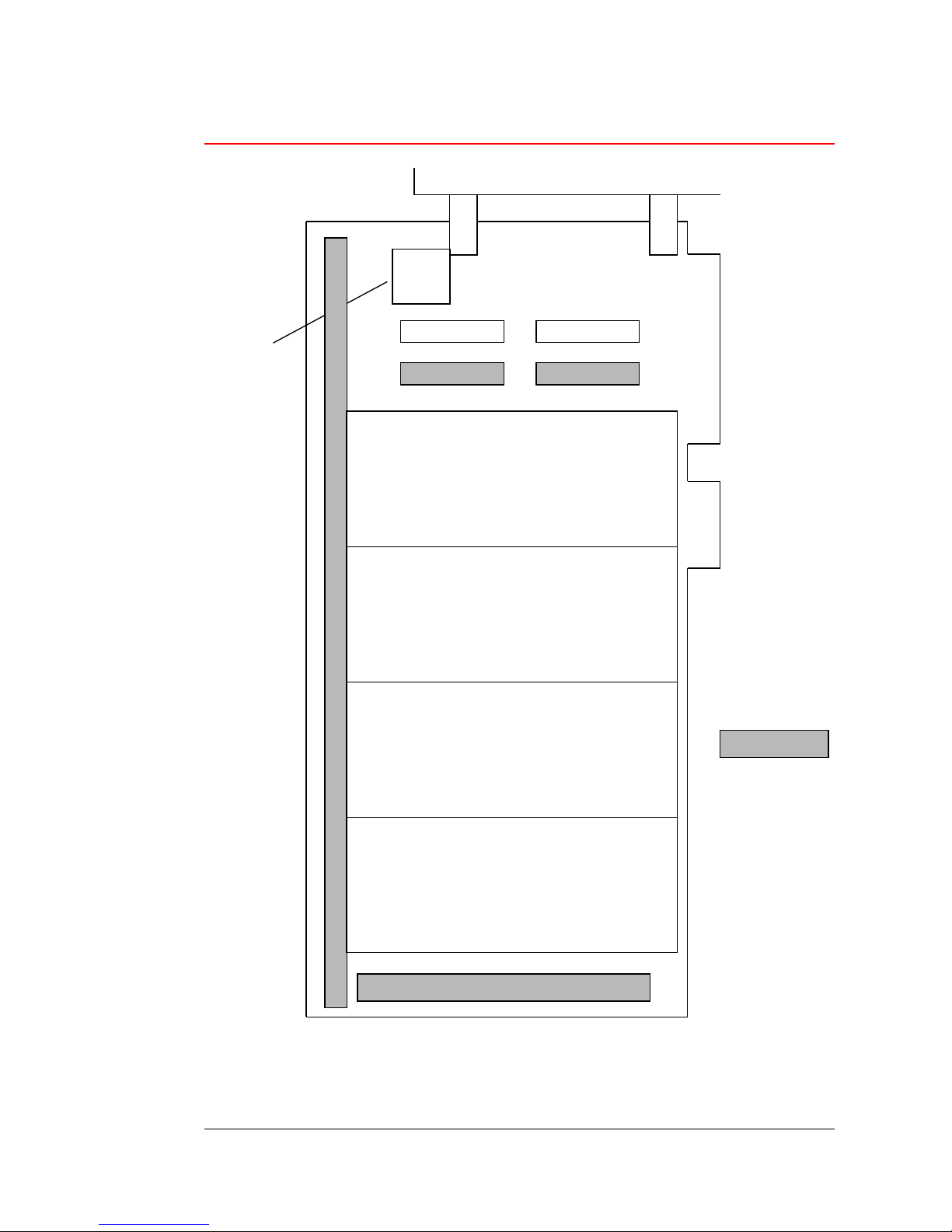
The next major interface with the "master" board is the set of TIM-40 control signals. This
set comprises of a Global Reset in and a Config signal. This Config signal is defined in the
TIM-40 Specification as a signal that is connected to all processors in the system, which
each processor drives as a default after reset. As Software is booted onto each processor, it
removes the drive from this signal. Thus the host or any other processor or hardware can
use this signal as an indication that the system has booted and is ready. It is suggested that
any 'dangerous' hardware uses this signal to disable its 'dangerous' portion until everything
has booted successfully and there is definitely some control in place. The HEP40E reset in
must be driven by a master board, and if the config line is used this must be connected
together on all boards.
The third interface is the JTAG port. This allows the JTAG ports of the 'C4xs to be
exercised by the relevant software tools. Interconnection between boards is made using a
simple one-to-one 14 way cable, which is the same as the XDS510 type cable, so the
HEP40E can also be a slave of an XDS510 type debug system.
The topology chosen for the HEP40E is described in detail later but to enable the user to
configure their own system topology there are also a number Comport Connectors. These
allow for connections to other 'C4xs either on this board or on other boards.
The "optional" J3 connector allowed for in the TIM-40 specification is not implemented
on the HEP40E. The pinout of all of the TIM-40 connectors can be found in the TIM-40
specification.
Care must be taken when connecting to any of the C40 signals available on the TIM-40
connectors.
In particular HUNT ENGINEERING have carried out many experiments and believes
that the Comport connections MUST be buffered in all circumstances. This process of
course reduces the performance in terms of speed but provides essential reliability.
The HEP40E uses the second generation HUNT ENGINEERING comport buffering
scheme, the advantages of which include reduced power consumption and higher
bandwidth. These are NOT compatible with the earlier scheme used by HUNT
ENGINEERING or with schemes used by other vendors.
Other signals known to be sensitive to "abuse" are the H1 and H3 clock signals. These are
not used on the HEP40E.
The HEP40E uses the TIM-40 connectors FX4C-80S-1.27DSA which allows for no
components on the Motherboard, in the area under a module as defined in Table 3 in the
TIM-40 specification.
The height of components on the underside of the module, that can be tolerated by this
motherboard, are defined by the module connectors as defined in table 2 of the TIM-40

8 HUNT ENGINEERING HEP40E USER MANUAL
specification.
The HEP40E has a socketed crystal oscillator to drive the TIM-40 clock input. This is
buffered by the board, and can be fitted with whichever frequency you require your
modules to run at. Please note the use of this clock by the modules is optional, as they
might have their own Xtal oscillators.
This socket is intended for plastic bodied type oscillators such as type number SG531 from
Seiko Epson, which are in a 0.3" 8 pin DILtype body but with only 4 pins.
However a more conventional type of oscillator module in a metal can also be used, such
as the IQXO22C series from IQD.
The socket has four pins as shown below
Reset
There are two sources of reset on the HEP40E:
* 'Reset in' on the 5 pin control connector.
* 'Auto reset'.
Depending on the setting of the reset jumper, the reset used for all TIM modules and the
host comports can be selected. The 'Reset in' signal must be taken to a logic low to assert
the reset and high again to de-assert the reset. This signal must be driven at all times as a
floating reset signal will cause spurious operation. The inputs to the HEP40E reset are TTL
level inputs.
1
2 HEP40E Reset
3 Reset in
If 'Reset in' from the "Control in" connector is required then a jumper link should be fitted
between pins 2 and 3 of the reset select. If 'Auto reset' is required then no jumper should
be fitted to the reset select, but a jumper should be fitted on the "Auto reset" location.
The "Auto reset" will cause the TIM-40s to be reset for a short time after power up. This is
intended for use with the HUNT ENGINEERING FLASH modules to self boot a
system.
The HEP40E provides a buffered version on the "Control Out" connector which can be
3 = TTL frequency outGnd 2
4 = +5Voltsno-connect

9 HUNT ENGINEERING HEP40E USER MANUAL
used to drive further slaves without fanout problems. This is also a TTL level signal,
suitable for connecting directly to the reset input on any HUNT ENGINEERING
motherboard.
The TIM-40 reset is buffered and used to drive an LED labelled "RES" on the back of the
board near the control connector. This LED will illuminate when the TIMs are reset.

10 HUNT ENGINEERING HEP40E USER MANUAL
JTAG (IEEE 1149.1) Test Interface
The HEP40E can act as a JTAG slave (for its own TIMs, and optionally those on another
board).
The board has a JTAG input connector for use when the board is used as JTAG slave, and
a JTAG output connector which is used when not the last board in the JTAG chain. Three
jumpers are used to join up the scan path when this HEP40E is the last board on the
JTAG chain (they should only be fitted when this is the case).
Most conventional 'C4x debugging software uses a board.cfg file to define the number
of processors in the scan path, and to assign them names.
A typical entry in a board.cfg file would be
"CPU_0" TI320C40
The first entry in this file represents the last CPU in the chain, i.e. for two HET40SXs in
slots 1 & 2 of the HEP40E there would be two entries in the board.cfg file, and the
first one would represent the HET40SX in slot 2 of the HEP40E.
Please note that any empty TIM-40 slots will be automatically shorted out in the chain, so
an HEP40E with only 2 processing TIM-40s fitted to any two slots of the HEP40E will
only have 2 'C4xs in the scan chain. Also note that any multi-processor TIM-40s fitted will
need an entry for each processor.
Also I/O modules with no processor do not need to appear in the board.cfg file.
The board.cfg file must be "compiled" into the file board.dat using the "composer"
program.
System examples
1. Single board system, using remote debugging such as XDS510.
The three JTAG jumpers used to join up the scan path should be fitted.
Now the JTAG chain for the 4 TIM-40 slots on the HEP40E can be controlled via the
JTAG IN connector. This is a standard 14 way JTAG connector so can accept the cabling
from TI's XDS510 system or from other HUNT ENGINEERING products.
2. Multi board system, using the JTAG master interface.
The first board, such as a HEPC2E, should have the jumper labelled "JTAG MAST" fitted,
but the three JTAG jumpers in the top left of the board should not be fitted.
On the other HEP40E boards in the system the three JTAG jumpers in the top left of the
board should not be fitted. There should be a one to one connection from the JTAG
OUT connector of each board to the JTAG IN connector of the next board. Only on the
last board in the chain should the three JTAG jumpers used to join up the scan path be
fitted.
Now the JTAG chain for the TIM-40 slots on all of the boards in the connection can be
controlled by the JTAG MASTER.
PLEASE NOTE even when you are only using the debugging tools with the HEP40E but
not the Comport interface, there must be a valid reset connection to all processors.

11 HUNT ENGINEERING HEP40E USER MANUAL
Config
There is system wide Config line. This signal is open collector and hence requires a pull up.
To connect this pull up fit a shorting link to the jumper labelled 'CONFIG'. This should
only be fitted on the master board in a system.
The Config is an important feature in a TIM-40 system where many I/O modules may be
disabled until the Config line goes high. This is used to prevent a 'C4x from booting from
an I/O stream, but will prevent such an I/O module from working until all processors
have released their Config line. Refer to the user manuals of the relevant processing TIM-
40s for instructions on how to release the Config line.
The Config signal is provided on the Control connectors to facilitate the connection of
multiple boards together all on the same Config line.
The Config is buffered and used to control an LED labelled "CONF" on the back of the
board near the control connector. This LED will illuminate when the TIM's Config signal
is asserted low.

12 HUNT ENGINEERING HEP40E USER MANUAL
IIOFs
The IIOF0 and IIOF1 signals on each of the TIM modules are used the following way:
- IIOF0 signals are pulled high, buffered and brought to the IIOF LEDs on the backside
of the board.
Whenever the TIM module asserts this signal low the relevant LED will be switched on.
Another buffered version of this IIOF is presented on the TIO pins on the I/O
connector. These signals are TTL outputs and can drive
Iol = -10mA ( Vout = 0.5V max)
Ioh = 15mA ( Vout = 2.0V min)
- IIOF1 signals are meant to be incoming 'C40 interrupt sources from the I/O connector.
Interrupt sources from the connector are buffered before they drive IIOF1 on the TIM
module, those buffers will be enabled by a rising edge on the TIM module's IACK signal.
Make sure that you go through an IACK cycle on the relevant 'C40 before monitoring any
interrupts on IIOF1.
If the 'C4x is booted via comport as normal, an IACK instruction will occur at the end of
the boot sequence.
The 'C4x can choose whether to poll these inputs or to set up interrupts. The inputs are
pulled high on the HEP40E with 10K, and are buffered with a TTL gate that requires
Iil = -1.6mA max ( Vin 0.5V)
Iih = 1.0mA max (Vin 5.0V )

13 HUNT ENGINEERING HEP40E USER MANUAL
Comport Connector
The 'C4x Comport is a parallel communications 'bus' which can transmit in either
direction, but to change that direction a 'Token' must be passed between the
communicating processors. This scheme relies on the fact that 3 of the 'C4x Comports
power up (or get reset) with a token and the other 3 power up (or get reset ) without a
token. Care must be taken to only connect a reset_to_input comport to a reset_to_output
comport. The cables available from HUNT ENGINEERING are polarised in such a way
as to prevent incorrect connection. Care should be taken to ensure that any cables
provided by the user are similarly polarised.
To allow interconnection within or between boards it has been found that the Comports
must be buffered and that care must be taken in cabling these Comport connections. A
polarised scheme for providing a buffered Comport at a connector is shown below:-
*CSTRB 1 O O 2 Ground
*CRDY 3 O O 4 Ground
D0 5 O O 6 TERMGND 0
D1 7 O O 8 TERMGND 1
D2 9 O O 10 POLARISE 0
D3 11 O O 12 Ground
D4 13 O O 14 Ground
*CREQ2 15 O O 16 Ground
D5 17 O O 18 POLARISE 1
D6 19 O O 20 Ground
D7 21 O O 22 Ground
*CREQ1 23 O O 24 Ground
*CACK 25 O O 26 Ground
The polarisation of the on-board connectors is as follows:-
POLARISE 0 POLARISE 1
Cut Short Pin Reset_to_output Comport
Pin Cut Short Reset_to_input Comport
So as to limit power consumption ground return to the terminating resistors packs and
data buffers have also been placed on these connectors meaning that they will not draw
current when the cable is not fitted
TERMGND 0 TERMGND 1
buffer and Rpack enable Gnd Reset_to_output Comport
Gnd Buffer and Rpack enable Reset_to_input Comport

14 HUNT ENGINEERING HEP40E USER MANUAL
The CREQ1 and CREQ2 signals are the only signals that are not bi-directional, but are a
buffered permanent representation of the CREQ signal at the 'C4x pin at that end of the
comport connection. This enables the buffering scheme to delay the direction switch of
the buffers until the signals have been driven to the far 'C4x, regardless of cable length.
CREQ1 CREQ2
Driven Input Reset_to_output Comport
Input Driven Reset_to_input Comport
For short distances i.e. connections on the same board, an IDC connector on a standard
ribbon cable is suitable, however for longer distances it has been found necessary to utilise
'special' cabling. - Contact your distributor for advice!
The Buffering scheme used on the HEP40E is the second generation HUNT
ENGINEERING comport buffering scheme. This has the advantage of increased
bandwidth and reduced power consumption.
This is NOT compatible with the first generation scheme.
It should be noted if trying to connect a non HUNT ENGINEERING product to this
connector, that the signals are not inverted from the 'C4x signals but that they are
terminated in an equivalent 100* and that for correct operation the product being
connected should both provide this termination and have sufficient drive capability to drive
this termination on the HEP40E.
If you are attempting to design your own hardware to interface with the HEP40E please
ask for the application note that covers this subject.

15 HUNT ENGINEERING HEP40E USER MANUAL
Comport Connections on the HEP40E
The HEP40E has hardwired Comport connections as follows:-
BC = buffers and connector. These are labelled with the slot number and the port number.
The comment in brackets is RTO for Reset_to_output and RTI for Reset_to_input, all are
polarised as described above. Also as the power consumption rises for each cable end
fitted.
These comport connections CANNOT be interconnected with earlier generations of
HUNT ENGINEERING comport buffering schemes which can be identified by their
different polarising schemes.
Reset
JTAG
0 B 3
5 B 2
0 B 3
5 B 2
0 B 3
5 B 2
4 1
BC BC
4 1
BC BC
4 1
BC BC
4 1
BC BC
BC 3
BC 2 0 BC
5 BC
Slot
1Slot
2
Slot
3Slot
4

16 HUNT ENGINEERING HEP40E USER MANUAL
Pinout of JTAG Connectors
The JTAG input connector is a standard 14 way JTAG connector, compatible with the
Texas Instruments' XDS510. The JTAG output connector provides signals that go though
a 14 way ribbon cable connected one-to-one that will drive a standard 14 way JTAG
connector like the JTAG input connector. Thus multiple boards can be connected by
simple ribbon cable links.
JTAG IN
EMU1 O O EMU0
GND O O TCK
GND O O TCK_RET
GND O O TDO_RET
XO PD
GND O O TDI to slot 1
TRST O O TMS
*
JTAG OUT
N/C X O N/C
GND O O TCK buffered
GND O O TCK_RET
GND O O TDO_RET
GND O O PD
GND O O TDO from slot4
TRST O O TMS buffered
*
O = pin present, X = pin removed for polarisation
The PD jumper connects the PD signal to +5V when fitted (last board only)
The TDO jumper joins "TDO from slot 4" to "TDO_RET" when fitted (last board only)
The TCK jumper joins "TCK buffered" to "TCK_RET" when fitted (last board only).

17 HUNT ENGINEERING HEP40E USER MANUAL
Pinout of Control Connectors
The control out header is and control in header is
Reset in Reset In
Ground Ground
Reset out Polarising
Polarising Polarising
Config Config
So Standard HUNT ENGINEERING control cables can be used to connect multiple
boards together as follows :-
Master Board Slave board
Reset Out--------------------------------------------------- Reset In
GND-------------------------------------------------------- GND
Config ----------------------------------------------------- Config
and further slave boards can be added in the same way, as long as their reset and Config
jumpers are Configured correctly.

18 HUNT ENGINEERING HEP40E USER MANUAL
Pinout of I/O Connectors
The I/O connector is pinned out as follows:-
*
Buffered IIOF0 slot 1 O X
Buffered IIOF0 slot 2 O O Buffered to IIOF2 slot 1
Buffered IIOF0 slot 3 O O Buffered to IIOF2 slot 2
Buffered IIOF0 slot 4 O O Buffered to IIOF2 slot 3
X O Buffered to IIOF2 slot 4

19 HUNT ENGINEERING HEP40E USER MANUAL
Physical Dimensions of the Board
A full length AT board is 4.8 inches by 13.3 inches overall.
The 0mm limit on component height of motherboard components under the TIM-40s is
not violated by the HEP40E
The maximum height of the components on the back of the HEP40E is 3mm.
If a "Processing module" such as the HET40SX, or HETWIN is fitted to the HEP40E, the
total width of the assembly is 20mm, but if an I/O module is used, the connectors may
make the total thickness more.
The HEP40E is fitted with a blank panel which may be changed to provide some I/O
connectors but this could violate the CE marking of the board (see later section)

20 HUNT ENGINEERING HEP40E USER MANUAL
Power Requirements of the HEP40E
The HEP40E only uses power from the 5V TIM-40 supply, but it must be remembered
that +-12v is supplied to the modules on the board, so when fitted with modules it might
require these supplies also.
The maximum rating of the HEP40E without any comport cables fitted is 0.75A, but the
typical value is nearer 0.4A.
0.1 amp must be added for each comport cable that is inserted into the board.
Table of contents