HunterGas HUNTER HAWK 4 MKII User guide

1
HUNTER HAWK 4
MKII
GAS STOVE
Instructions for Installation and Servicing
Please leave this instruction booklet with the user after the installation is complete. Leave the
system ready for operation and instruct the user in the correct use of the appliance and operation of
its controls. Please refer to the appliance data plate for the specific model type.

2
JIN04MKIIC_V1 10/01/17
Contents
INSTALLATION & COMMISSIONING
CHECKLIST ................ .......... ......................................... 3
TECHNICAL DATA…………………………............................... 5
INSTALLING THE APPLIANCE………………………………. ....... 6
FLUE ARRANGEMENT …………………………………............................................................................8
ADDITIONAL AIR VENTING (GB ONLY) ............. ........................................................................8
OPENING THE STOVE DOOR……………………………………................................................................9
GAS SUPPLY CONNECTIONS........... .................. ......................................................................10
TESTING SUPPLY PRESSURE ........... .................. ......................................................................10
INSTALLATION OF THE FIRE-BED INTO THE
STOVE………….…………………………………………………………. 11
FITTING THE CANOPY – (OPTIONAL)................. ......................................................................14
SPILLAGE MONITORING SYSTEM……………………………… ............................................................14
SERVICING INSTRUCTIONS…………............................... 16
SPARES................................... ......................................................................... 17
Please read these instructions carefully
This appliance is intended for use on a gas installation with a governed
meter.
It is important that your stove is correctly installed as Hunter Stoves Limited cannot accept
responsibility for any fault arising through incorrect installation.

3
INSTALLATION & COMMISSIONING CHECKLIST
PURCHASE INFORMATION
Dealer/Retailer Name
Address
Telephone Number
Email
Date Purchased
APPLIANCE INFORMATION
Date Installed
Appliance Stock Code
Appliance Description
Serial Number
INSTALLER INFORMATION
Installer Name
Gas Safe Registration Number
Company Address
Telephone Number
Email

4
JIN04MKIIC_V1 10/01/17
Signature:
Print Name:
COMMISSIONING CHECK (Complete & Sign)
Pass
Fail
Flue is correct for the appliance
Flue flow test
Spillage test
Gas soundness & let by test
Standing gas pressure
mbar
Appliance working pressure (on High Setting)
mbar
Gas rate
m³h
Has a remote control been fitted? (yes/no)

5
TECHNICAL DATA
NATURAL GAS
Nominal Gas Pressure
20mbar
Supply Gas Type/Category
G20/I2H
Injector Type/Marking
59
Heat Input (Gross)
Full
Low
4.7kW
3.5kW
Gas Flow Rate (m3/h)
Full
0.447
NOxClass
4
Efficiency Class
2
Countries of Destination
GB & IE Only

6
JIN04MKIIC_V1 10/01/17
STOVE DIMENSIONS
Diagram 1: Stove Dimensions
INSTALLING THE APPLIANCE
Pre-installation notes
1. Check the stove data plate to establish the gas type required. The data plate can be found on
a chain at the top left rear corner of the stove.
Before installation check that the local distribution conditions, nature of the gas and
pressure, and adjustment of the application are compatible.
2. A GAS SAFE REGISTERED INSTALLER or equally recognised competent person must fit the
appliance. That person is legally responsible for the safe installation of the appliance with
due regard to all relevant local and national building regulations.
3. All outer surfaces of the stove excepting the gas control knobs are defined as working
surfaces.
4. Installation site
Any installation area previously used for a solid fuel fire or stove would probably be deemed
suitable for the appliance.
5. The stove must not be installed onto a combustible wall. Any combustible materials must
be removed from behind the appliance.
6. The appliance must be sited on a non-combustible hearth of minimum 12mm thickness.
7. The hearth should be edged or raised to prevent combustible floor finishes (e.g. Carpet)
from being laid too close to the appliance.

7
8. Opening Clearances: for the relevant clearance distances for installing the appliance in an
opening see diagram 2 and table 1.
Diagram 2: Opening Clearances
Table 1: Clearance Distances for Installing the Appliance
IMPORTANT NOTE! Adequate clearance must be given between the appliance and the walls so that a
satisfactory spillage test can be performed as detailed on page 17.
MINIMUM CLEARANCE DISTANCES TO:
DIMENSION
DESCRIPTION
COMBUSTIBLE MATERIAL
NON-COMBUSTIBLE MATERIAL
A
Side of stove to wall
150mm
100mm
B
Top of stove to underside of
opening or shelf
250mm
200mm
C
Rear of stove to wall
150mm
100mm
D
Minimum distance for hearth to
extend in front of stove
50mm
50mm

8
JIN04MKIIC_V1 10/01/17
FLUE ARRANGEMENT
Prior to installation the flue the chimney should be given a precautionary clean to ensure its entire length is
free from blockages. Any flue dampers must be permanently fixed in the open position or removed
altogether. The chimney should be smoke tested to ensure soundness.
The GAS SAFE REGISTERED ENGINEER commissioned to install this appliance is wholly responsible for
deciding the suitability of any flue arrangement to operate in conjunction with this gas appliance.
The chimney or flue system that is to be fitted to the Hawk 4 MKII gas stove must comply with the current
rules in force.
The Hawk 4 MKII gas stove is also suitable for other specific class II installation arrangements: pre-cast flues,
ridge-vent flues, and pre-cast chimney block.
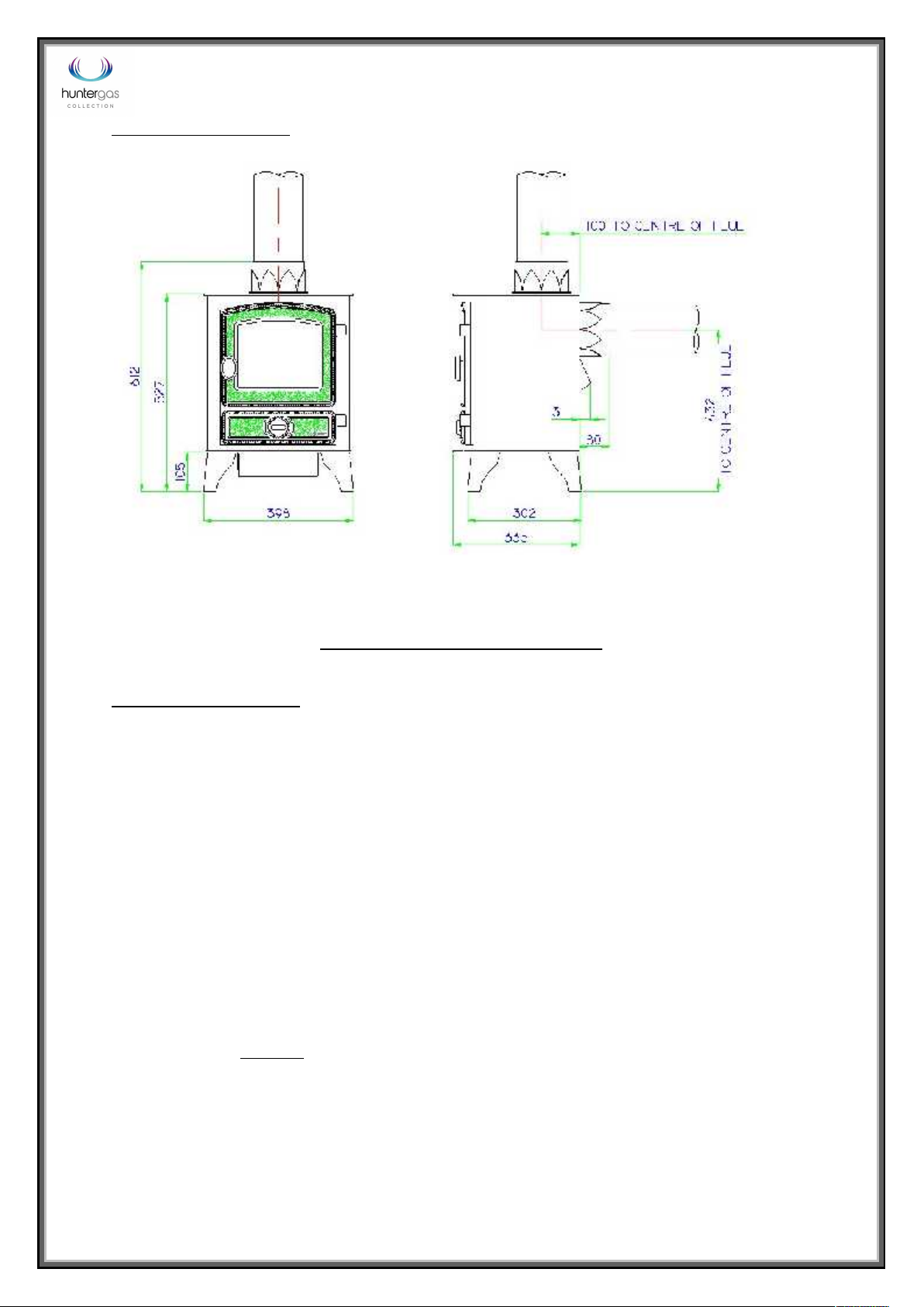
It is suggested to run flue pipe at least 615mm vertically from the unit before there are any changes in
direction of the flue system. Wherever possible horizontal runs of the flue system should be avoided.
The flue must have a minimum of 2.6 meters of vertical height measured from the top of the stove to the
bottom of the terminal outlet.
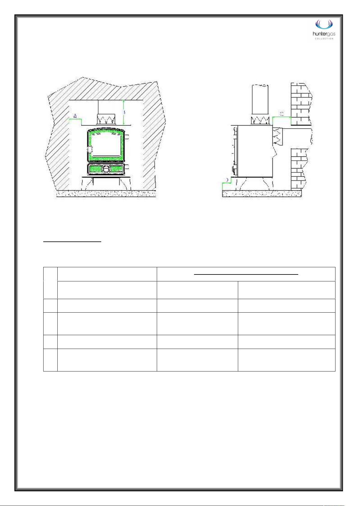
Please note for rear flue appliances it is recommended that the vertical flue run be established as soon as is
practical from the rear flue exit. (Caution should be taken locating the exit of the flue as explained in ‘The
Building Regulations - Document J’.)
ADDITIONAL AIR VENTING (GB ONLY)
The supply gas heat input into the appliance is nominally less that 7kW. Therefore, under the directives of
the current Health and Safety Executive gas safety and use regulations (Gas Safety [Installation and Use]
Regulations 1998 Approved Code of Practice and guidance) no additional air vents are required in the room
in which the appliance is situated.

9
OPENING THE STOVE DOOR
NOTE! This appliance must never be used if the glass door panel is broken, removed or if
the door is open.
Before gaining access to the burner tray, first make sure that the stove is switched off and is cold.
Firstly remove the door handle by turning anticlockwise. Keep turning until the handle is completely
removed, as shown in photo 1.
The door-fixing bolt can then be removed using a 13mm spanner as shown in photo 2.
Photo 1: Door handle removal
Photo 2: Removing door fixing bolt

10
JIN04MKIIC_V1 10/01/17
GAS SUPPLY CONNECTIONS
The appliance is supplied with an 8mm Bundy pipe and
an 8mm compression elbow to allow easy connection
to the mains gas supply. This supply gas pipe should
incorporate a gas service isolation tap that is situated
within 1 metre of the application.
Photo 3: The 8mm Bundy pipe being fitted to the gas
inlet on the valve. The compression joint is tightened
with a 14mm open-ended spanner.
TESTING SUPPLY PRESSURE
1. Gas pressure at the appliance is measured via the test point on the tube going to the control
valve (circled in diagram 3b).
Turning the screw approximately half a turn anti-clockwise with a small flat-bladed screwdriver opens
the test point.
ALWAYS CLOSE TEST POINTS AFTER USE!
2. The gas pressure at the appliance is measured with the appliance running at full rate.
(For information on how to achieve ‘full rate’ read ‘Adjusting Between High and Low Output Settings’ in
the ‘Lighting the Appliance’ section of the User Instructions).
Burner Gas Pressure should be:
19mbar ± 1.0mbar for Natural Gas
3. The supply pressure test point (shown in diagram 3a) is on the left-hand side of the control valve.
Diagram 3a: Supply Pressure Test Point. Diagram 3b:
Burner Pressure Test Point.

11
INSTALLATION OF THE FIRE-BED INTO THE STOVE
IMPORTANT NOTE
CERAMIC COALS AND LOGS GET VERY HOT! NEVER ATTEMPT TO HANDLE HOT COALS OR LOGS
WITH BARE HANDS AND NEVER PLACE HOT COALS OR LOGS ON OR NEAR COMBUSTIBLE SURFACES.
HUNTER STOVES LTD ACCEPTS NO RESPONSIBILITY FOR ANY INJURY HOWEVER CAUSED WHILST
HANDLING HOT COALS, LOGS OR CERAMICS.
FIRE-BED ARRANGEMENT
This appliance can be fitted with ‘log effect’ ceramics. The fire-bed is constructed of a base ceramic
and 6 loose logs.
Photo 4: Log Effect
Ceramics
1. Place the base ceramic into the fire (photo 5).
Right: Photo 5 - Installing the base ceramic (matrix).
Base Ceramic
Log B
Log A
Log C
Log D1
Log D2
Log E

12
JIN04MKIIC_V1 10/01/17
1. The first log to be placed Log A. This is
placed around the left-hand front flame port hole in
the matrix. The log should sit comfortably in place on
the matrix as shown in photo 6.
Photo 6: Installing Log A.
3. The second log to be placed is Log B. The single end
is positioned to the right of the second front flame
port hole in the matrix, in the slot provided. The right-
hand fork at the opposite end of the log is then
located in the cut-out on the top edge of the back of
the base ceramic. The left-hand fork should then rest
on the edge of the matrix and the side of the stove.
As shown in photo 7.
Photo 7: Installing Log B.
4. Log C sits in a groove to the right of Log B
behind the third flame port hole in the
matrix. The top of the log sits in the cut-out
that is located on the top edge of the back
of the base ceramic, as shown in photo 8.
Photo 8: Log C
Log D1should be positioned behind the furthermost
right-hand flame port hole, resting against the back
upright of the base ceramic, making sure that it is
not directly above the rear flame port hole.
Log D2sits on the short arm of Log B, with the top of
it sitting in the cut-out on the rear upright at the
back of the base ceramic (photo 9).
Photo 9: Logs D1& D2.

13
Log E is located to the left of the
furthermost right hole in the matrix,
the top resting on log C to the left of it
(photo 10).
The log picture is now complete.
The stove should be lit and the
flame picture checked with the door
sealed shut. Any adjustments to the
flame picture can then be made as
required.
Photo 10: Complete Log Picture.

14
JIN04MKIIC_V1 10/01/17
FITTING THE CANOPY – (OPTIONAL)
There is an optional canopy available for the Hunter Hawk MKII.
The canopy can be simply slid into place on the top plate of the stove body (Shown in photo 11),
making sure that the two welded tabs (located either side of the canopy) fit under the top plate.
The canopy is then secured in place by tightening the two fixing screws (one located either side of
the canopy) with a flat-bladed screwdriver, shown in photo 12.
Photo 11: Fitting a canopy Photo12: Securing the canopy.
TEST FOR SPILLAGE
A spillage test MUST be carried out before the appliance is left
with the customer.
Close all doors and windows in the room containing the fire
before the test is carried out. Complete the Ceramic Coal, or
Log picture, close the door and replace the handle.
1. Ensure that the fire is burning at full rate for a
minimum of 5 minutes.
2. Run a smoke match along the edge of the draught
diverter, both sides of the TTB Bracket (as shown in
photo 13).
3. Most of the smoke should be drawn into the draught diverter. If not, leave the stove running
at full rate for a further 10 minutes and then repeat the test.
4. If there is a fan in an adjoining room the spillage test must be repeated with the fan running
and all connecting doors between the fire and fan open.
5. If there are still problems the chimney/flue or ventilation may require
attention. The stove should not be used until the fault is rectified.
Photo 13: Spillage Test

15
Spillage Monitoring System
The appliance is fitted with spillage system (TTB), which is located near the draught diverter and
operates to shut the appliance off if the evacuation of combustion products is interrupted (for
example caused by lack of flue pull or flue blockage).
The spillage system MUST NOT be adjusted, modified or put out of action by the installer. The
spillage system MUST NOT be removed or ‘bridged out’ for any reason. If the spillage system is faulty
and requires replacement, only genuine Hunter Stoves parts should be used.
Nuisance shut down may occur if the stove is not installed in accordance with the clearance
distances set out in diagram 2 on page 7.

16
JIN04MKIIC_V1 10/01/17
SERVICING INSTRUCTIONS
Any recommendations made here are in addition to the standard servicing procedures used
by the servicing engineer.
A GAS SAFE registered fitter using only original Hunter Stoves parts should carry out
servicing.
1. Open the stove door as described on Page 9.
2. Carefully lift-off the ‘coals/logs’ and remove the ceramic matrix.
3. Using a soft brush, clean away any lint or light carbon soot deposits out of the gas
ports on the burner top plate.
4. Replace the ceramic matrix and loose coals/logs as per the fire-bed arrangement
instructions (Page 11) using all re-serviceable coals/logs and any new replacements.
5. Check the gas operating pressure and pipe work for soundness, carry out a spillage
test and check the condition of the flue system.
6. If for any reason the TTB switch is removed or replaced during a service, we
recommend wiping the mating surfaces clean and re-applying a thin smear of 150°C
Heat Sink Compound to the face of the TTB switch.

17
SPARES LIST
PART DESCRIPTION
PART NUMBER
TTB SWITCH, 150º
494-0851
TTB LEAD ASSEMBLY CN VARIANT
CFB06ARRT004CN
GLASS PANEL (D TYPE DOOR)
HCR06058
GLASS PANEL (STANDARD DOOR)
HCR06039
GLASS CLIP & SCREW
HHR08046
DOOR ROPE KIT (D TYPE DOOR)
SCPHKDRSK
DOOR ROPE KIT (STANDARD DOOR)
SCPHKRSK
GAS BURNER FULL ASSEMBLY, 4kW NATURAL GAS, MANUAL CONTROL
GYB04NYM
OXIPILOT, 6kW & 4kW GAS BURNER
CFB06102
GAS VALVE, MANUAL
CFB06100
KNOB, MANUAL GAS VALVE, 6kW & 4kW GAS STOVE RANGE
CFB06101
INTERUPTOR BLOCK, CN SUPPLY, 6kW & 4kW GAS STOVE RANGE
CFB06104
LOG KIT CERAMICS, 4kW GAS STOVE
GC04LK
8 Emperor Way, Exeter Business Park, Exeter, Devon. EX1 3QS
www.hunterstoves.co.uk
Email: info@hunterstoves.co.uk
Table of contents
Popular Stove manuals by other brands

wiking
wiking Bazic 3 Mounting

Nordica
Nordica GIADA Instructions for installation, use and maintenance

Holiday
Holiday 8425 Operating instructions and repair parts list

Italiana Camini
Italiana Camini MARIU Installation, use and maintenance

Enviro
Enviro C-10804 owner's manual

Cola
Cola TERMO-PERLA Installation, use and maintenance manual