Hussmann Q3-DV-4 User manual

/SPECIALTY
MERCHANDISER
Q3
USER MANUAL
0619
DELI VERTICAL
Q3 -Q3-DV-4VercalCase
-Q3-DV-5VercalCase
-Q3-DV-6VercalCase
-Q3-DV-8VercalCase
-Q3-DV-10VercalCase
-Q3-DV-12VercalCase
-Q3-DV-22.5IS/OSVercalCase
-Q3-DV-45IS/OSVercalCase Remote

2
DOE 2012
Energy Eciency
Compliant
Hussmann refrigerated merchandisers congured for sale f
or use in the United States
meet or surpass the requirements of the DOE 2012 energy eciency standards.
Notice 3
General Information 4
Case Sections 5
Installation 6
Unloading
Receiving Case 6
Snapping Chalk Lines 6
Placement 7
Lifting / Panels
Q3DV Lifting and Transport Instructions 8
Front Body Panel Install 9
Fasten Front Body Panel Install 9
Fasten Rear Body Panel Install 9
Leveling
Leveler Adjustment 10
Shim The Case 10
Joining
Parts List 11
Q3-DV Canopy Adjustment 12
Joining Preparation 15
Refrigeration 18
Piping
Refrigerant 18
Refrigerant piping 18
Line Sizing 18
Oil Traps 18
Refrigeration Spec Sheets 19
Table of Contents
Electrical 20
Electrical Info
Merchandiser Electrical Data 20
Electrical Connections 20
Field Wiring 20
IdenticationofWiring 20
Remove Rear Raceway 21
Electrical Conduit (Electrical Box) 21
Electrical Wiring Diagram 22
User Information 33
General
Start Up 33
Load Limits 33
Maintenance
Case Cleaning 34
Exterior Surfaces 34
Interior Surfaces 34
Troubleshooting 36

3
WARNING
1. DO NOT overload or stand over top of case. Glass breakage may occur if
precautions are disregarded.
*Broken glass can cause lacerations, cuts, and puncture wounds which
may result in severed arteries or tendons, amputations, eye injuries, or
exposure to disease.
Notice

4
CaseDescripon:
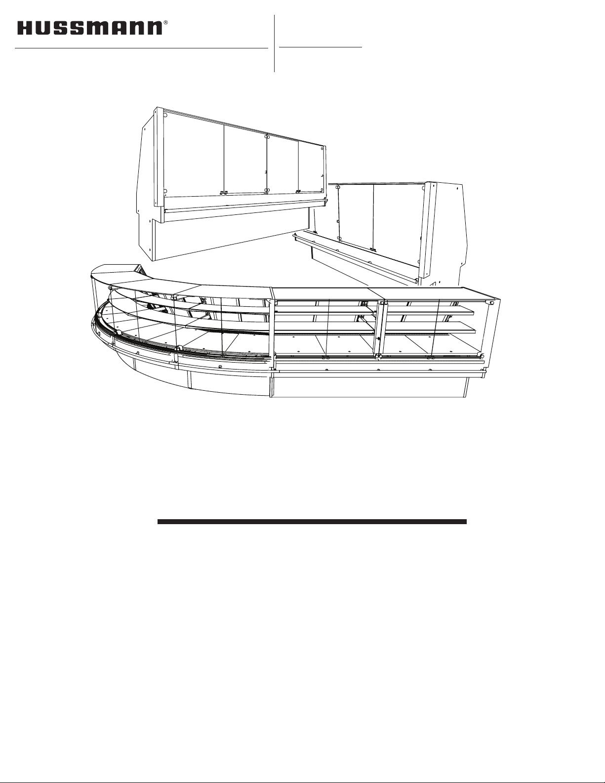
Description: Refrigerated vertical Deli/Bakery Merchandiser
Shipping Damage: All equipment should be thoroughly examined for shipping damage before and
during unloading. This equipment has been carefully inspected at our factory and the carrier has
assumed responsibility for safe arrival. If damaged, either apparent or concealed, claim must be
made to the carrier Immediately.
Apparent Loss or Damage: If there is an obvious loss or damage, it must be noted on the freight bill
or express receipt and signed by the carrier’s agent; otherwise, carrier may refuse claim. The carrier
will supply necessary claim forms.
Concealed Loss or Damage: When loss or damage is not apparent until after all equipment is
uncrated, a claim for concealed damage is made. Make request in writing to carrier for inspection
within 15 days, and retain all packaging. The carrier will supply inspection report and required claim
forms.
Shortages: Check your shipment for any possible shortages of material. If a shortage should exist
and is found to be the responsibility of Hussmann Chino, notify Hussmann Chino. If such a shortage
involves the carrier, notify the carrier immediately, and request an inspection. Hussmann Chino will
acknowledge shortages within ten days from receipt of equipment.
Hussmann Chino Product Control: The serial number and shipping date of all equipment has been
recordedinHussmann’slesforwarrantyandreplacementpartpurposes.Allcorrespondence
pertaining to warranty or parts ordering must include the serial number of each piece of equipment
involved, in order to provide the customer with the correct parts.
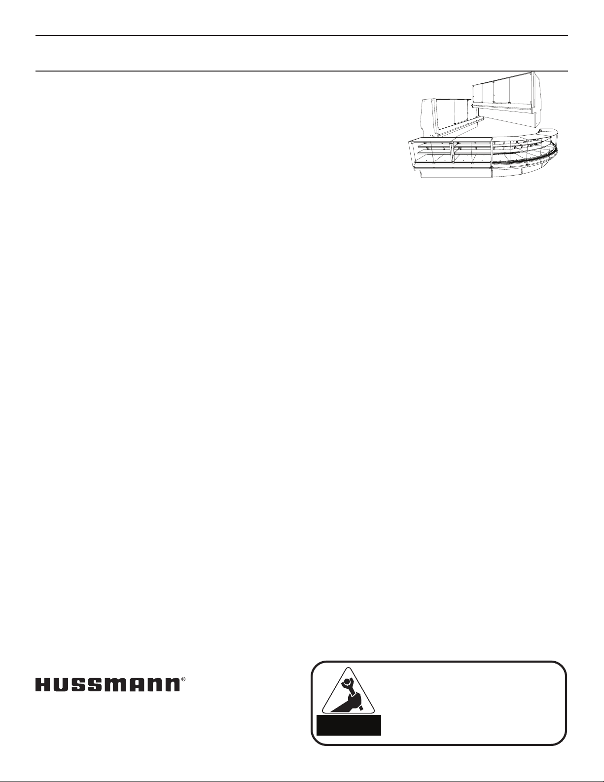
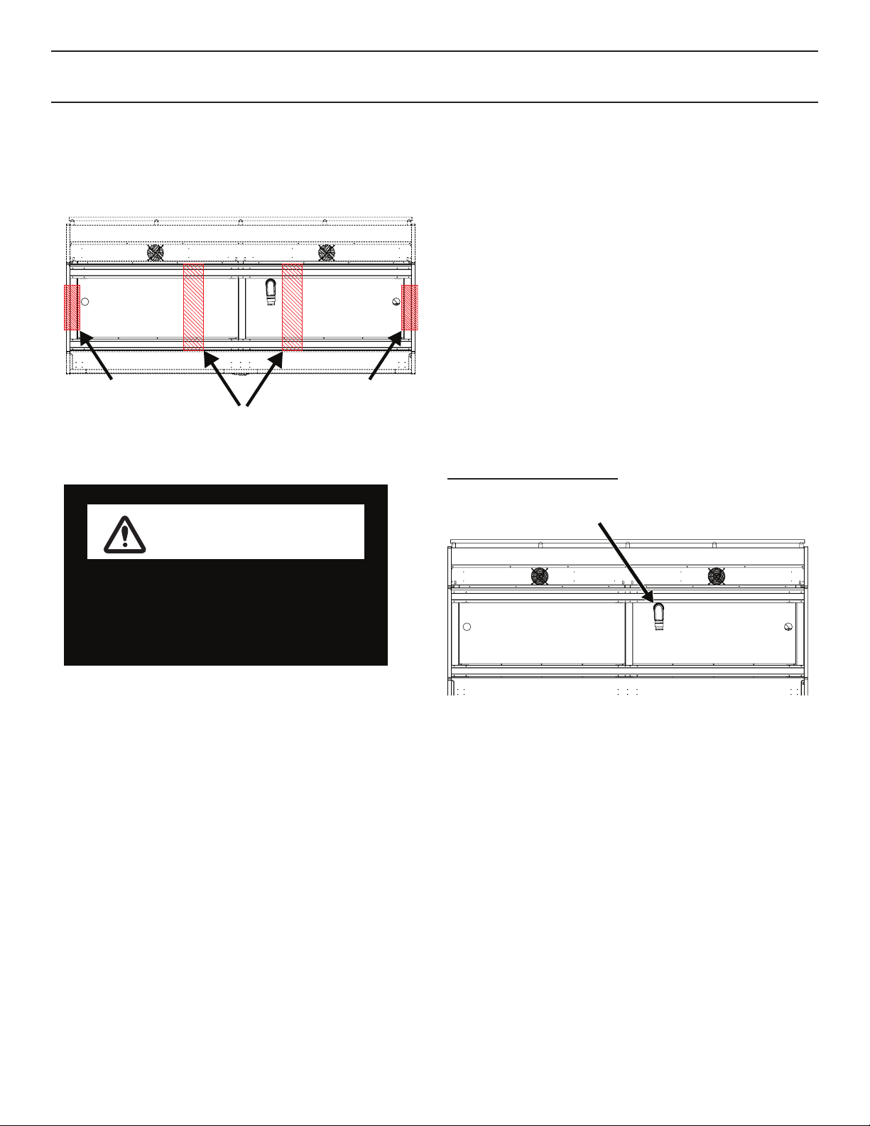
Location/Store Conditions: The Q3-DV refrigerated merchandiser has been designed for use only
in air conditioned stores where temperature and humidity are maintained at 80°F and 55% relative
humidity or 75°F and 55% relative humidity. DO NOT allow air conditioning, electric fans, ovens, open
doors or windows (etc.) to create air currents around the merchandiser, as this will impair its correct
operation.
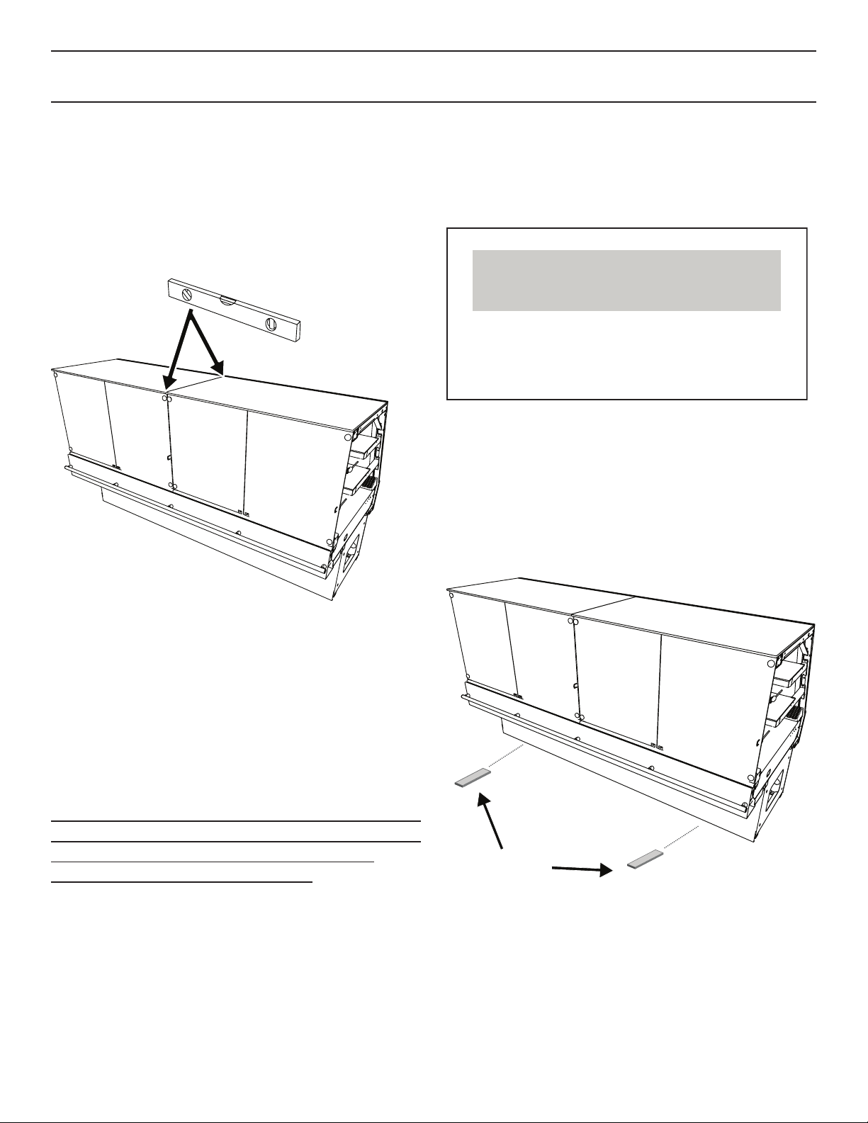
This equipment is to be installed
to comply with the applicable
NEC, Federal, State , and Local
Plumbing and Construction
Code having jurisdiction.
AT TENTION
INSTALLER
/CHINO
A publication of HUSSMANN®Chino
13770 Ramona Avenue • Chino, California 91710
(909) 628-8942 FAX
(909) 590-4910
(800) 592-2060
Keep this booklet with the case at all times for future reference.
General Information

5
24 3/4
(629)
26
1/2
(673)
23
1/8
(587)
253/4
(654)
27
7/8 (708)
52
1/4
(1327)
12(305)
14(356)
227/8
(581)
153/8
(391)
10 3/8
(264) 251/8
(638) 57/8
(149)
413/8
(1051)
Q3-DV Multi-Deck Service Deli Case
8
(203)
Elec Drain Refrig
5
(127) 6 1/8
(156)
End Panels
11/8
(29)
C
L
417/8
(1064)
281/8
(714)
221/8
(562) 251/8
(638)
48
(1219) 72
(1829) 96
(2438) 144
(3658)
Q3-DV, BV
customer side
57/8
(149)
10 3/8
(264)
Case Sections

6
Installation
NOTICE
Do NOT remove Foam Blocks from shelves
and glass until the merchandisers are
positioned for installation. Shelves or
merchandising glass may be damaged.
Wrapped Top
and Shelves
Foam Blocks
in place
Warning
Labels
Loose
Items
Case is to arrive at store as was shipped form
factory. See reference above for proper shipment
referencing. (not actual case)
Receiving Case
Upon receiving your new Hussmann Case all
equipment should be thoroughly examined for
shipping damage before and during unloading.
This equipment has been carefully inspected at
our factory. Any claim for loss or damage must
be made to the carrier. The carrier will provide
any necessary inspection reports/ or claim form.
If there is obvious loss or damage, it must be
noted on the freight bill or express receipt and
signed by the carrier’s agent; otherwise carrier
may refuse claim.
Snapping Chalk Lines
Preparepermanentpositioningbymarkingoors
with Chalk snap lines where cases are to be
located. Chalk lines are to run along the base or
legs of cases.

7
Placement
Important: See lifting instructions to properly lift
case when being placed on dollies or permanent
location. (See page 8 for Lifting Instructions.)
First remove Blocks and L Brackets around the
case from pallet.
Remove Block
and L bracket
Proceedbysettingforkliftsunderspeciedloca-
tions as instructed in the Lifting Instructions
(pg. 8.) Be careful not to damage drains or near
components when placing forks underneath
case. A spotter is mandatory to ensure no dam-
age is caused to the case. Lift case and replace
with dollies, place near or in permanent location.
Inser
t Forks
Underneath
Deck
Movethextureascloseaspossibletoitsper-
manent location and then remove all packaging
and preparing to remove off Skid. Remove all
separately packed accessories such as kits, and
Installation (cont’d)
panels. Check for damage before discarding
packaging.
In the case a fork lift truck is not available follow
the demonstration below to properly lift case us-
ing a Johnson Bar (J-Bar) to place on dollies to
trafcfromstartpointtoplacementarea.
Place J-Bar underneath base of merchandiser
to gain leverage, once lifted place Dollie under-
neathrstendandslowlylowerontodollieen-
suring merchandiser is placed on stable location.
Proceed to opposite end and repeat.

8
Q3DV Lifting and Transport
Instructions
1. The Q3-DV can be lifted by a forklift at typical
lifting points.
Forklift Points
(Underneathe
Deck)
J-Bar Lift Points
(Underneathe
Base Structure)
J-Bar Lift Points
(Underneathe
Base Structure)
WARNING
Improper placement of forks may damage
drainage piping. Use a spotter when placing
forks. Make sure that piping will not be dam-
aged. Use J-Bars or Jacks if forks cannot be
used safely
2. Ensure lower body panels are removed be-
fore lifting with a forklift. Serious damage will
occur if the body panels are not removed.
3. Make sure that fork spacing and width will not
damage drain or come in contact with piping,
or electrical lines
4. Be sure that the forks are long enough to
support beyond the center of the case but not
damage near components. Check for proper
balance before moving. A minimum fork
length of 36” is recommended for 68” wide
cases
Installation (cont’d)
5. The Q3-DV merchandiser can be raised at
one end underneath the deck with a forklift to
allow the placement of rollers or dollies.
6. Evenly support the entire base structure on
rollers or dollies before attempting to move.
Each Base Leg must have its own dollie to
properly support the case.
Lifting Points are typical and dependent upon
size of case and refrigeration application, drain-
agecongurationswillcallforaltercationsin
Lifting Zones.
Belowarethefollowingdrainagecongurations
and lifting should be altered to the expected
model.
Q3 DV Drain Location
Drain

9
Installation (cont’d)
Fasten Rear Body Panel Install
(1) Align pre drilled holes to base of case
(2) Secure top and bottom of rear panel using
fasteners as shown below.
Allow front and rear body panels to slide down
resting on support hooks. 2.Place L Bracket
along the underside of deck to hold body panel
top in place against base wall of case.
Front Body Panel Install
A Phillips Screw Driver/Bit will be needed to
install body panels.
To begin Bottom panel assembly place panel A
along side the base of the case and lower panel
on to support hooks along the bottom of the base
(See illustration below for details).
A
Detail A
Resting Hooks
Panel A
P
anel B
Fasten Front Body Panel Install
(1) Secure Panel A with top fasteners only.
(2) Overlay Panel B to bottom of Panel A as
shown in illustration below
*Note Panel B will be attached freely with no pre
drilled holes.
1
1
2
2
Panel A
Panel B

10
Installation (cont’d)
Leveler Adjustment
Position the case at the highest point. Set a long
magnetized level (4ft [1220 mm] or more) on
either underneath the deck or on top of the case.
Ensure to level case from front to back and side
to side.
Level
(4 ft[1220mm])
Shim The Case
Use shims at each corner of the case to level
out any discrepancies in order to optimize case
performance and proper drainage.
Note: Shims are not Factory supplied. Contractor
should carry available components. Metal Shims
are recommended for use to eliminate any
deterioration from shims over time.
Note:Toavoidremovingconcreteooring,begin
line up levelling from the Highest point of the
storeoor.
NOTICE
Longer length cases may require shims
along the center portion of the case to
maintain proper case performance and
drainage.
Shim

11
3/8"-16NUT/BOLT
LOOSE3PER JOINT
ALIGNMENTPIN
0376408 3PER JOINT
3/8"-0.5625" OD WASHER
LOOSE4PER JOINT
1/4"-0.5625"ODWASHER
LOOSE/TOPCANOPYONLY1PER JOINT
#10SELFTEPPING SCREW
0376408 10 PERJOINT
1H97637
Joiningpart3 1PER JOINT
1H97784
Joininhpart4 1PER JOINT
143394
joiningpart2 1PER JOINT
1H63905
Joiningpart1 1PER JOINT
732RTV SILICONE SEALANT
LOOSE1PER JOINT
deVan-BUTYL
LOOSE1PER JOINT
GASKET
LOOSE 10'RER CASE
Parts List

12
Installation (cont’d)
Q3 DV CANOPY ARM ADJUSTMENTPROCEDURE
LEVEL1
LEVEL2
ACCESS COVER
WRAPPERBULKHEAD
TURN BUCKLE
CONNECTING ROD
STEP
1. Ensure case is leveltothe ground.Check levelat
thebulkheadasshown (LEVEL1).
STEP
2. Unscrewand remove access covers.
STEP
3. loosen topand bottomhinge vertical adjusment screws
STE
P4.Place levelonthe topofthe upperarmsasshown (LEVEL 2)
STEP
5. Using a1
/
2"open-endedwrench, turn Turn buckle connectingrod
untillevel 2indicates that thearm is level(Note that some turn
bucklesmay be reverse thread.. Test turningdirection by observing
theeect of turn direction.)
IMPORTANT: Pre Loading Canopy Arm
STEP
5. Afterreaching level(On LEVEL2)turnthe connectors
twofullrotations in thedirection that raises thecanopy.
2
4
H
DETAIL H
Direction
of preloading
2complete
turns
1

13
Q3 DV FRONTGLASS ADJUSTMENTPROCEDURE
DETAIL A
B
DETAIL B
ISOVIEW
FRONTVIEW
HINGEACCESS COVER
HORIZONTAL ADJUSTMENT:
Rotate thefront screwtoincrease
or decrease theglass gap(1+/-2 mm).
DEPTHADJUSTMENT:
Rotate therearspiraltechcam to increase or
decrease theglass gap(+/-3mm).
HEIGHT AJUSTMENT:
Loosen themountingplate (2 screws)
adjust glasstopositionand tighten
screws (+/- 3mm).
WARNING: loosen both upperand lower
hinge before making height adjustments.
Adjust vertical gaptomaximum
toloranceof0.125".
Adjust horizontal gaptomaximum
toleranceof0.125".
STEP 1: Un-screw andremoveall access covers from
thetop andbottomhinges.
STEP 2: Adjust horizontal andverticalgapsofeach glass
(see detailA).
STEP 3: Ensure thegapsbetwen panel do not
exceed more than 0.125" see detail B.
Installation (cont’d)

14
Q3 DV FOCALPOINT RE-POSITIONING
CANOPY LIGHT
Backward
Forward
ROTATE
STEP 1: Hold canopy lightwith bothhands. Each hand should be as
close
to the end as posibl
e(shownbelow).
STEP 2: Pushcanopylight with equalforce forwardor
backward to desired location.
STEP 3: Rotate lighttodesired aim for application.
STEP 4: Tuck anyexcess wiring throughthe wiring chase.
I
DETAIL I
Left hand
hold location
Righthand
hold location
1
1
NOTE: FOCAL POINT PATENT PENDING
2
3
4
Q3-DV Case
Joining Preparation
Installation (cont’d)

15
Q3 DV JOININGCASETOCASE-STEP 1
Gaskets
(factory installed)
Butyl
Apply
gasket to case area as shown.
1
/
2"(13 mm) gasket areappliedinthe recess along
the top canopy frameand vertical arm.
Apply
butyland silicone to case area as shown.
Apply silicone a
pplicationasshown to properly
seal area.Ensure thatbeads of silicone areminimum of 1
/
2"to
maximize adhesive joiningpreventingair leakage. Be sure to wipe
o anyaxcesssiliconearoundcases.
IMPORTAN
T
.Do notstretch gasket,especialy around thecorners
.Donot butt gasket,alwaysoverlap
.Removepaper backing aftergaskethas been applied
C
Applybeadofsilicone
to theexteriorfaceofgasket
Gaskets
(factory installed)
DETAIL C
Installation (cont’d)

16
1)
Level case using shim
sateachcornerofthe case to levelout anydiscrepanciesinorder to optimize case
Performanc
eand proper
drainage. (See Q3 DV Canopy Arm Adjustment Procedure)
2) Pushcases together untilthe alignmentpin intrudetothe assigned opposite holes.
4) Using3/8"Hardware, boltcasetogetherusing washersfor allfivelocations.
For
Leveling
Access holesfor instalingjoining bolts.
Q3 DV JOININGCASETOCASE-STEP 2
JoiningRiv Nuts areinstalled on
theright side of thecasebydefult.
Joiningholes apears on the
rightsideofthe case by defult,
andrequire boltsand washers.
Installation (cont’d)

17
Installation (cont’d)
Joiningpart3
Joiningpart4
1) Remove deck pans adjacenttothe casesjoining line.
2) Remove rear modular DSCH adjacenttothe casesjoining line
3) Installjoining part 1and 2(seepartlist) usingsilicone adhesive andpushbackall theway.
4) Installtop joiningpartusing silicone adhesive (see part list)and push allthe wayforward.
5) Usingdoubleside3M® adhesive tape installjoining parts3and4(see part list)
andensurealigned symmetricallyonthe topofthe casesjoining line.
6) Reinstalldeckpansand modularDSCHs.
Q3 DV JOININGCASETOCASE-STEP 3
D
DETAIL D
Joining
part 1
Joining
part 2

18
Refrigeration
Refrigerant
The correct type of refrigerant will be stamped
on each merchandiser’s serial plate. The case
refrigeration piping is pressurized with a nitrogen
holding charge, leak tested and factory sealed.
Before making refrigeration hookups, depress
universal line valve (Shraeder Valve) to ensure
that coils have maintained pressure during ship-
ment. In the case pressure was not maintained
contact your Hussmann Service Tech for further
assistance.
Serial Plate Location
CAUTION
Refrigeration lines are under pressure.
Refrigerant must be recovered before
attempting to make any connections.
Refrigerant piping
The refrigerant line connections are at the right
hand end of the case (as viewed from the front)
beneath the display pans. The merchandiser will
beforehand ensure an earlier cut hole through
the pod to exit the merchandiser for the refrigera-
tion lines. After connections have been made,
make certain to seal this outlet thoroughly if not
sealed at factory already. Seal both the inside
and outside. We recommend using an expanding
polyurethane foam insulation.
Line Sizing
Refrigerant should be sized as shown on the
refrigeration legend that is furnished for the store
or according to the ASHRAE guidelines
Oil Traps
P-traps (oil traps) must be installed at the base
of all suction line vertical risers.
It is the contractor's responsibility to install
case(s) according to local construction and
health codes.
Piping Location

19
DELI / BAKERY, SERVICE CASE, VERTICAL GLASS REVISION DATE 04/27/18
HUSSMANN - Q3-DV/BV (CHINO)
REFRIGERATION DATA:
3' 0.3 0.4 0.6
4' 0.4 0.6 1.3
3',4',5',6',8',10',12' 390 390 24 24 5' 0.5 0.7 2.1
22.5°OS 1940 1940 24 24 6' 0.6 0.8 3.1
45°IS 2080 2080 24 24 8' 0.8 1.1 1.4
45°OS 900 900 24 24 10' 0.9 1.4 2.5
12' 1.3 1.6 3.0
**FRONT DISCHARGE AIR MEASURED INSIDE AIR CURTAIN HONEYCOMB 22.5°OS 0.3 0.6 1.1
***REFRIGERATION NOTES: 45°IS 0.2 0.7 1.2
1) BTU'S INCLUDE CANOPY LIGHTS. ADD 10 BTUS/SHELF/FT FOR EACH SHELF (LIGHT) 45°OS 0.2 0.3 0.1
2) AHRI 1200 RATING POINT FOR ENERGY CONSUMPTION COMPARISON ONLY
3) USE DEW POINT FOR HIGH GLIDE REFRIGERANTS. CARE SHOULD BE TAKEN TO USE THE DEW POINT IN P/T TABLES
FOR MEASURING AND ADJUSTING SUPERHEAT. ADJUST EVAPORATOR PRESSURE AS NEEDED TO MAINTAIN THE
DISCHARGE AIR TEMPERATURE SHOWN.
4) RATING CONDITION IS NSF TYPE I, 75°F/55% RH
REFRIGERATION DATA CONTINUED:
1 1.125
DELI / BAKERY 32 29 OFF TIME 40 45 N/A 2 1.125
ELECTRICAL DATA:
STANDARD FANS, HEATERS, LED LIGHTS (115 VOLT)
3'
16.7 15 0.12 8 10.08 9 0.16 19 0.13 15 0.30 34 0.96 110 1115 15
4' 1 6.7 20 0.12 8 2 0.15 18 0.30 35 0.18 21 0.48 55 0.87 100 1115 15
5' 1 6.7 25 0.12 8 2 0.15 18 0.35 40 0.23 26 0.57 66 1.09 125 1115 15
6' 4 6.7 15 0.48 32 2 0.15 18 0.42 49 0.26 30 0.69 79 1.30 150 1115 15
8' 4 6.7 20 0.48 32 2 0.15 18 0.60 69 0.36 41 0.96 110 1.74 200 1115 15
10' 4 6.7 25 0.48 32 3 0.23 26 0.70 80 0.45 52 1.15 132 2.17 250 1115 15
12' 6 6.7 20 0.72 48 3 0.23 26 0.90 104 0.54 62 1.44 166 2.61 300 2115 30
22.5°OS 1 6.7 15 0.12 8 1 0.08 9 0.17 19 0.13 15 0.30 35 0.87 100 N/A N/A N/A
45°IS 2 6.7 15 0.24 16 1 0.08 9 0.16 18 0.13 15 0.29 33 0.65 75 N/A N/A N/A
45°OS 1 6.7 20 0.12 8 1 0.08 9 0.09 11 0.04 4 0.13 15 0.87 100 N/A N/A N/A
OPTIONAL HIGH OUTPUT LED LIGHTS (115 VOLT)
CASE ENERGY USAGE DATA:
AMPS WATTS AMPS WATTS AMPS WATTS
3' N/A N/A N/A N/A N/A N/A
4' 0.39 45 0.26 30 0.66 75
5' N/A N/A N/A N/A N/A N/A
6' N/A N/A N/A N/A N/A N/A
8' 0.78 90 0.53 61 1.31 151
10' N/A N/A N/A N/A N/A N/A
12' 1.17 135 0.79 91 1.97 226
22.5°OS 0.21 24 0.23 26 0.43 50
45°IS N/A N/A N/A N/A N/A N/A
45°OS N/A N/A N/A N/A N/A N/A
TEMPERATURE (ºF)
CAPACITY ***
(BTU/HR/FT) (TOTAL
FOR WEDGES)
VELOCITY
(FT/MIN)
ANTI-SWEAT
HEATERS (ON
FAN CIRCUIT)
AMPS
TERM.
TEMP
(°F) COIL
ONLY
31.6
BLADE
DIA.
(IN.)
BLADE
PITCH (°) AMPS WATTS AMPS WATTS
AIRSWEEP FAN
# OF
FANS
MAX. LED LOAD
(W/ ALL OPTIONS)
0.11
22.5° OS
23.121952
7.31
10.28
45° OS
25.3316
7.26
11.26
90° OS 0 11.40
0.11
45° IS
18.25096
4.95
8.14
3',4',5',6',8',10',12'
6.104
1.85
2.69
22.5° IS
0
1.10
AMPS
TDA/V (ft
2
/ft)
(ft
3
wedges)
ACTUAL CDEC
(KWh/day/ft)
(KWh/day wedges)
CASE LENGTH
MAX ALLOWABLE
CDEC (KWh/Day/ft)
(KWh/day wedges)
WATTS AMPS WATTS
#
OUTLETS
VOLTS
CONVENIENCE OUTLETS
(OPTIONAL)
CASE LENGTH
CANOPY
LIGHTS
H.O. LED
OPTIONAL SHELF MAX. H.O. LED
LOAD
CASE LENGTH /
WEDGES
AMPS WATTS AMPS WATTS
EVAPORATOR FANS CANOPY
LIGHTS LED
OPTIONAL LED
SHELF LIGHTS
# OF
EVAP
FANS
NSF 7
EST.
REFG.
CHRG.
(LBS)
(R404A)
USAGE
CUT IN
(ºF)
CUT
OUT
(ºF)
ELEC. THERMOSTAT / AIR
SENSOR SETTINGS
DEFROST
TYPE
DELI / BAKERY
30~34
225~250
END PANEL WIDTH KEY
# OF END
PNLS
END PNL
WIDTH
(IN.)
TOTAL ADDED
LENGTH (IN.)
DELI / BAKERY
30~34
225~300
DRIP
TIME
1.125
DELI / BAKERY
30~34
225~300
CASE
LENGTHS/
WEDGES
CASE USAGE
2.25
DEFROST
WATER
(LBS/DAY/FT)
TIME
(MIN)
DEFROST
FREQUENCY
(#/DAY)
DELI / BAKERY
26~30
225~300
GLYCOL (20°F
INLET, 6° RISE)
RATING
CONDITION
EVAPORATOR
DISCHARGE
AIR ** (°F)
GPM PSI
NSF 7
AHRI
1200
NSF 7
CASE
LENGTHS
AHRI
1200
NSF 7
Refrigeration Spec Sheets

20
Electrical
Merchandiser Electrical Data
Technical data sheets are shipped with this
manual. The data sheets provide merchandiser
electrical data. Refer to the technical data sheets
and merchandiser serial plate for electrical
information.
Electrical Connections
All wiring must be in compliance with NEC and
local codes. All electrical connections including
both supply circuits are to be made in the electri-
cal J-Box.
ALWAYS CHECK THE SERIAL PLATE FOR
COMPONENT AMPERES
Field Wiring
Field wiring must be sized for component am-
peres stamped on the serial plate (refer to pg 16
for location). Actual ampere draw may be less
thanspecied.
Identication of Wiring
Leadsforallelectricalcircuitsareidentiedby
colored plastic bands. These bands correspond
to the color code sticker (shown below) located
inside the merchandiser’s wireway cover.
WARNING
--LOCK OUT/ TAG OUT--
To avoid serious injury or death from electrical
shock, always disconnect the electrical power
at the main disconnect when servicing or
replacing any electrical component. This
includes, but is not limited to, such items as
doors, lights, fans, heaters, and thermostats.
This manual suits for next models
7
Table of contents