Arneg Athos 2 VCB Guide

Athos 2
05060087 02 13/05/2010 1
ILLUSTRAZIONI
ILLUSTRATIONS
ABBILDUNGEN
ILLUSTRATIONS
ILLUSTRACIONES
ɂɅɅɘɋɌɊȺɐɂɂ
1
2
3
4
860
1280
500
250
256
1106
160
132
860
811
1280
160
500
250
256
132
SELF VCB
ARNEG S.p.A.
VIA VENEZIA 58 - CAMPO SAN MARTINO - PADOVA - ITALY
CODICE
ITEM
MATRICOLA
S/N
SBRINAMENTO
DEFROSTING
SUPERF.ESP.
DISPLAY AREA
REFRIGERANTE
REFRIGERANT
CLASSE
CLASS
ILLUMINAZIONE
LIGHTING
MASSA
WEIGHT
COMMESSA
W.SCHED
ORDINE
W.ORD.
ANNO
YEAR
W
m
2
IP
kg
VHz W A
1
2
3
5
9
12
14
16
17 18
11
4
7
15
13
10
68
W
CONTIENE GAS FLUORURATI AD EFFETTO SERRA
DISCIPLINATI DAL PROTOCOLLO DI KYOTO
CONTAINS FLUORINATED GREENHOUSE GASES
COVERED BY THE KYOTO PROTOCOL
Max 25mm
30cm
w
a
t
e
r
CHEMICALS
Rif. 1
Rif. 2

Athos 2
205060087 02 13/05/2010
5
6
7
Prg
Set
mute aux
aux
def
HACCP
OPTIONAL
937
425 325
430
230
R404A H
2
O
580
111305
1250
582 325
430
478
478
478
230
R404A H
2
O
580
111305
1875
490
325 325
430
230
R404A H
2
O
H
2
O
H
2
O
580
111305
2500 - 3120 - 3750
625
325
430
230
R404A H
2
O
580
111305
325
Rif. 3
Rif. 4
Rif. 5
Rif. 6

Athos 2
05060087 02 13/05/2010 3
8
9
30
500
500
200
S1
S3
S2
S3
S1
S1
S3
Rif 1

Athos 2
405060087 02 13/05/2010
10
G.VERDE/YELLOW-GREEN
BLU/BLUE
MARRONE/BROWN
BLU/BLUE
MARRONE/BROWN
G.VERDE/YELLOW-GREEN
LEGENDA
TERMOSTATO TEMP.CAREL IR32SE(OPZIONALE)
TEMP.THERMOSTAT CAREL IR32SE(OPTIONAL)
A
END-DEF.THERMOSTAT CAREL RTA200G230(OPT)
TERMOSTATO F.SBRIN.CAREL RTA200G230(OPZ)
A1
TRASFORMATORE 240/12V(OPZIONALE)
TRANSFORMER 240/12V(OPTIONAL)
TC
LIGHT SWITCH
INTERRUTTORE LUCI
SA1
N1NI I N 2 N R1NI I
p.04
p.02
SA1
p.03
p.01
DEFROST HEATER
RESIST.SBRINAMENTO
N2 N R1
VENTIL.EVAPORAT.
EVAPORATOR FANS
3R1
N
2
WORK SURFACE HEATER
C.CALDO PIANO LAVORO
1N
1
GLASS HEATER
C.CALDO VETRATA
1S1 S1
S1 S1
S2 S2
SONDA FINE SBRINAMENTO
END-DEFROST PROBE
S2
S2 S2
S1
THERMOSTAT PROBE
SONDA TERMOSTATAZIONE
34
34
N L N L11 12
11 12
245678
12 4567
12VAC
38
A1 A
TC
13
NL
S1 S1 S2 S2
SONDA NTC 10K 25°C
PROBE NTC 10K 25°C
S1-2
M
THERMOSTATS SUPPLY
ALIM.TERMOSTATI
COMANDO TERMOSTATO
THERMOSTAT OUTPUT
THERMOSTAT PROBE
SONDA TERMOSTATAZIONE
ALIM.CAVI CALDI
HEATERS SUPPLY
VENTILATORI EVAP.
EVAPORATOR FANS
RESIST.SBRINAMENTO(SOLO MT)
DEFROST HEATER(ONLY FOR MT)
SONDA FINE SBRINAM.(SOLO MT)
END-DEFROST PROBE(ONLY FOR MT)
COMANDO TERMOS.FINE SBRIN.
END DEF.THERMOSTAT OUTPUT
ALIM.LUCE
LIGHT SUPPLY
S3 S3
WORK TEMPERATURE PROBE
SONDA TEMPERATURA DI ESERCIZIO
S3 S3
SONDA TEMPERATURA
TEMPERATURE PROBE
S3
NI I NI I
Schema elettrico Standard / Standard wiring diagram

Athos 2
05060087 02 13/05/2010 5
11
4
5
6
7
9
8
3
2
1
4
5
6
7
9
8
3
2
1
G.VERDE/YELLOW-GREEN
BLU/BLUE
MARRONE/BROWN
BLU/BLUE
MARRONE/BROWN
G.VERDE/YELLOW-GREEN
QS
F1
5A
F2
5A
11
F5
1A
5AN
4B4A
08
09
KA1
04
03
L
N
KA2
5B
KA2
14
15
13
10
01
02
I
NI
FI
5A
07
12
1N2N1NI I
SLAVE 2
SLAVE 1
SA1
05
06
S1 S1 S2 S2 S3 S3
KA1 KA2
17
12V
0V
TC
FTR
0,5A
FA
0,5A
CAVO SCHERMATO 2x0,75 mm
2
G- +
IRMPXMB001
-+
A
30
31
19
18
16
24
22
23
25
26
27
28
29
21
20
LEGENDA
RELE' REFRIGERAZIONE
REFRIGERATION RELAY
KA2
TC
RELE' VENTILATORI
FANS RELAY
KA1
SAFETY TRANSFORMER 240/12V 3VA
TRASF.DI SICUREZZA 240/12V 3VA
INTERRUTTORE PRINCIPALE
MAIN CIRCUIT BREAKER
QS
S1-2-3
PROBE NTC 10K 25°C
SONDA NTC 10K 25°C
CONTROLLO CAREL MPX
CAREL MPX CONTROLLER
A
INTERRUTTORE LUCI
LIGHT SUPPLY
SA1
LEGENDA NUMERI-COLORI
GIALLO/VERDE-TERRA
SPECIFICATION NUMBERS-COLOURS
(1)=BLUE-NEUTRAL
(2)=BROWN-OPENING VALVE
(4)=ARANCIONE-RISCALDAMENTO
(3)=GREY-CLOSING VALVE
(2)=MARRONE-VALVOLA APERTA
(3)=GRIGIO-VALVOLA CHIUSA
(1)=BLU-NEUTRO
(4)=ORANGE-HEATING
YELLOW/GREEN-GROUND
5AN 5B
123
1
4
COLLEGAMENTO PER VALVOLA GLICOLE
CONNECTION FOR GLYCOLE VALVE
VALVOLA PER GLICOLE
VALVE FOR GLYCOLE
5AN
4B4A 5B1
TO REMOTE CPR UNIT
67
ALLA SCHEDA COMPRESSORE
VALVOLA L IQUIDA
SOLENOID VALVE
L-N ALIMENTAZIONE PER AUSILIARI
L-N POWER SUPPLY FOR AUXILIARY
1P+N 230V 50/60Hz
1P+N 230V 50/60Hz
I-N(I) POWER SUPPLY FOR LIGHTING
I-N(I) ALIMENTAZIONE PER ILLUMINAZIONE
IF POWER SUPPLY AND LIGHTING ARE COMMON,
PLEASE CONNECT L-I AND N-N(I).
L-I E N-N(I).
FORZA MOTRICE E ILLUMINAZIONE PONTEGGIARE
NEL CASO L'ALIMENTAZIONE NON SIA SEPARATA TRA
RED CONNECTOR
CONNETTORE ROSSO
RED CONNECTOR
CONNETTORE ROSSO
SERIAL CABLE 2x0,75 mm
2
DY
SONDA TERMOSTATAZIONE
THERMOSTAT PROBE
SONDA FINE SBRINAMENTO
END-DEFROST PROBE
S1 S1
S1
S2 S2
S2
N2
VENTIL.EVAPORAT.
EVAPORATOR FANS
3
N
2
WORK SURFACE HEATER
C.CALDO PIANO LAVORO
1N
1
GLASS HEATER
CAVO CALDO VETRATA
1
M
NI I NI I
G- +969581 82
SERIAL CABLE FOR RS 485
CAVO SERIALE RS 485
BELDEN TYPE 8761-62
COMANDO STAND-BY
STAND-BY INPUT
TEMPERATURE ALARM(NO)CONTACT
WORK TEMPERATURE PROBE
S3 S3
S3
SONDA TEMPER. DI ESERCIZIO
CONTATTO(NO)ALLARME TEMPER.
Schema elettrico MASTER / MASTER wiring diagram

Athos 2
605060087 02 13/05/2010
12
4
5
6
7
9
8
3
2
1
G.VERDE/YELLOW-GREEN
BLU/BLUE
MARRONE/BROWN
BLU/BLUE
MARRONE/BROWN
G.VERDE/YELLOW-GREEN
LEGENDA
TC
RELE' VENTILATORI
FANS RELAY
KA1
SAFETY TRANSFORMER 240/12V 3VA
TRASF.DI SICUREZZA 240/12V 3VA
S1-2-3
PROBES NTC 10K 25°C
SONDE NTC 10K 25°C
CONTROLLO CAREL MPX
CAREL MPX CONTROLLER
A
CONNECTION TO MASTER
COLLEGAMENTO AL MASTER
RED CONNECTOR
CONNETTORE ROSSO
CONNETTORE ROSSO
RED CONNECTOR
CONTATTO(NO)ALLARME TEMPER.
TEMPERATURE ALARM(NO)CONTACT
STAND-BY INPUT
COMANDO STAND-BY
INTERRUTTORE LUCI
LIGHT SUPPLY
SA1
DY
F1
5A
F2
5A
09
KA1
08
FI
5A
07
10
N2N 1 S1 S1 S2 S2NI I
1
2
3
4
5
6
7
9
8
2
6
1
5
8
7
4
3
2
6
1
5
8
7
MASTER
4
3
1
2
3
4
5
6
7
9
8
S2 S3
KA1
96958281 969581 82
IRMPX10001
-+
11
12V
0V
TC
FTR
0,5A
FA
0,5A
01
02
03
04
05
06
13
12
15
14
17
18
19
20
16
21
22
23
A
S1 S1
SONDA TERMOSTATAZIONE
THERMOSTAT PROBE
S1
S2 S2
SONDA FINE SBRINAMENTO
END-DEFROST PROBE
S2
S3 S3
WORK TEMPERATURE PROBE
S3
SONDA TEMPER. DI ESERCIZIO
321
N
VENTIL.EVAPORAT.
EVAPORATOR FANS
N
WORK SURFACE HEATER
C.CALDO PIANO LAVORO
1N
GLASS HEATER
C.CALDO VETRATA
1
M
2NI I NI I
Schema elettrico SLAVE / SLAVE wiring diagram

Athos 2
05060087 02 13/05/2010 7
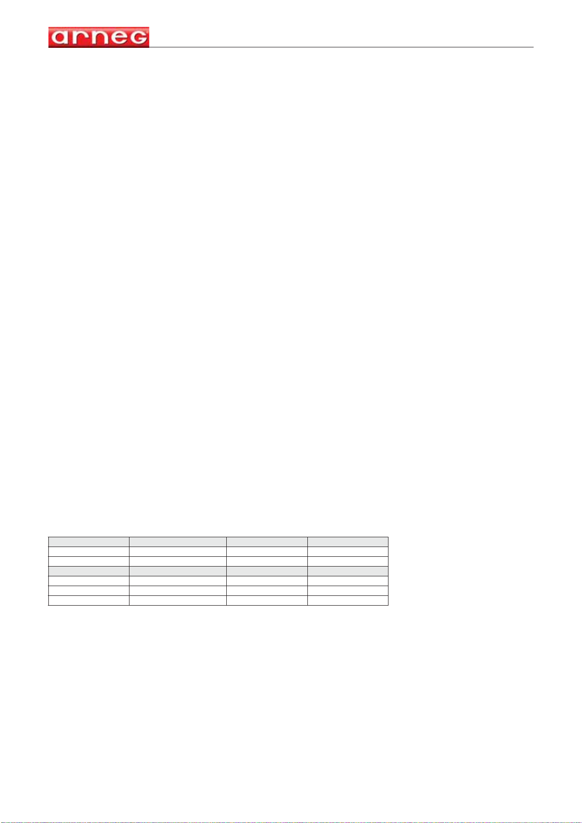
Dati Tecnici, Technical Data, Technische Daten, Données techniques, Datos Técnicos,
Ɍɟɯɧɢɱɟɫɤɢɟ ɯɚɪɚɤɬɟɪɢɫɬɢɤɢ
Modello, Model, Modell, Modele, Modelo,Ɇɨɞɟɥɶ VCB
Codice, Code, Kode nr., Code, Código, Ʉɨɞ 06214802 06214804 06214806 06214808 06214809
Lunghezza senza spalle, Length without ends, Länge ohne Seiten,
Longeur sans joues, Longitud sin laterales, Ⱦɥɢɧɚɛɟɡɛɨɤɨɜɢɧ
mm
1250 1875 2500 3125 3750
Temp. di esercizio, Working temperature, Betriebstemperatur,
Temp. de fonctionnement, Temperatura de trabajo, Ɋɚɛɨɱɚɹɬɟɦɩɟɪɚɬɭɪɚ
°C
+ 2°C / + 4°C
Temperature ammissibili, Allowed temperature, Zulässige Temperaturen
Températures admissibles, Temperaturas admitidas, Ⱦɨɩɭɫɬɢɦɵɟɬɟɦɩɟɪɚɬɭɪɵ-(Ts) 97/23 CE -
°C
Max + 32°C / Min - 10°C
Area espositiva aperta, Open display surface, Sichtbare Ausstellefläche , Surface d’exposition ouverte, Area
expositiva abierta, Ɉɬɤɪɵɬɨɟɗɤɫɩɨɡɢɰɢɨɧɧɨɟɉɪɨɫɬɪɚɧɫɬɜɨ
m
20,83 1,25 1,66 2,08 2,49
Superficie di esposizione orizzontale, Horizontal display surface, Gesamte Ausstellefläche, Surface d ’exposition
horizontale , Superficie de exposición de apoyo, Ƚɨɪɢɡɨɧɬɚɥɶɧɚɹɩɥɨɳɚɞɶɷɤɫɩɨɡɢɰɢɢ
m
21,26 1,89 2,52 3,14 3,77
Volume netto, Net volume, Netto inhalt, Volume net, Volumen neto,
ɑɢɫɬɵɣɜɟɫ
dm
3153 230 307 383 460
Potenza frigorifera, Refrigeration Power, Kühlleistung, Puissance frigorifique Potencia frigorígena, ɏɨɥɨɞɢɥɶɧɚɹ
ɦɨɳɧɨɫɬɶ
+2°C/+4°C
W
450 675 900 1125 1350
Refrigerante, Refrigerant, Kühlmittel, Réfrigérant, Refrigerante, ɏɥɚɞɚɝɟɧɬ R404A
Massima pressione ammissibile, Max allowed pressure, Maximal zulässiger Druck, Pression maximale
admissible, Máxima presión admitida, Ɇɚɤɫɢɦɚɥɶɧɨɞɨɩɭɫɬɢɦɨɟ Ⱦɚɜɥɟɧɢɟ-(Ps) 97/23 CE -
bar
29 bar
Valvola espansione, Expansion Valve, Expansion-Ventil, Valve d’expansion, Válvula de expansión,
Ɋɚɫɲɢɪɢɬɟɥɶɧɵɣɤɥɚɩɚɧ TES 2-0,11 TES 2-0,21 TES 2-0,45 TES 2-0,6 TES 2-0,6
Ventilatori, Fans, Gebläse, Ventilateurs, Ventiladores, ȼɟɧɬɢɥɹɬɨɪɵ
n° x W
2 x 16 4 x 16 4 x 16 5 x 16 6 x 16
Cavi caldi anticondensa, Anti-condensation hot cables, Kondenswasserschutzwarmkabel, Câble chauffant
anti-condensation, Resistencias anticongelamiento, ɇɚɝɪɟɜɚɬɟɥɶɧɵɟɤɚɛɟɥɢɩɪɞɨɬɜɪɚɳɚɸɳɢɟɨɛɪɚɡɨɜɚɧɢɟ
ɤɨɧɞɟɧɫɚɬɚ
W
58,4 88,4 117,6 147,7 177,6
*Resistenza di sbrinamento, Defrost heater, Abtauwiderstand,Resistance de dégivrage,Resistencias de
descongelation, Ɇɨɳɧɨɫɬɶɨɬɬɚɢɜɚɧɢɹ
W
460 690 920 1150 1400
Tipo di sbrinamento, Defrosting type, Abtautyp, Type de dégivrage, Tipo descongelation, Ɍɢɩɨɬɬɚɢɜɚɧɢɹ
Naturale, Off-cycle, Zeitabtauung, Dégivrage naturel, Parada simple,ɉɪɨɫɬɚɹɨɫɬɚɧɨɜɤɚ
Sbrinamenti consigliati, Recommended Defrosting, Empfohlene Abtauungen, Dégivrages conseillés,
Descongelaciones aconsejadas, Ɋɟɤɨɦɟɧɞɭɟɦɵɟɨɬɬɚɢɜɚɧɢɹ
n°/24h 4 x 45min.
Livello di rumorosità , Noise level, Schallpegel, Niveau de bruit, Nivel de ruido, ɍɪɨɜɟɧɶɲɭɦɚ
db (A)
< 60
Contenuto modificabile senza preavviso, Content that could be change without notice, Inhalt Veränderbar ohne Vorankündigung, Contenu modifiable sans préavis, Contenido modificable sin previo aviso, ɋɨɞɟɪɠɚɧɢɟɢɡɦɟɧɹɟɬɫɹɛɟɡɩɪɟɞɭɩɪɟɠɞɟɧɢɹ
*- OPTIONAL - Potenze elettriche totali assorbite, riferite alla tensione di alimentazione 230 V / 50 Hz, Total electric power absorbed referred to 230 V / 50 Hz electric input, Puissances électriques totales absorbées, en référence à la tension d’alimentation
230 V / 50 Hz, Potencias eléctricas absorbidas relativas a la tensión de alimentación 230 V / 50 Hz, Ɉɛɳɚɹɩɨɬɪɟɛɥɹɟɦɚɹɦɨɳɧɨɫɬɶɩɪɢɧɚɩɪɹɠɟɧɢɢɷɥɟɤɬɪɢɱɟɫɤɨɣɫɟɬɢ9+]
1. Dati tecnici
2. Technical data
3. Technische Daten
4. Données techniques
5. Datos Técnicos
6. Òåõíè÷åñêèå õàðàêòåðèñòèêè

Athos 2
Italiano
805060087 02 13/05/2010
Manuale di Installazione e Uso
INDICE
ILLUSTRAZIONI ................................................................................................... 1
Dati tecnici............................................................................................................. 7
Introduzione - Scopo del manuale/Campo di applicazione................................... 9
Presentazione - Uso previsto (Fig. 1).................................................................... 9
Norme e certificazioni............................................................................................ 9
Identificazione - Dati di targa (Fig. 2).................................................................... 9
Il Trasporto (Fig. 3)................................................................................................ 10
Ricezione e prima pulizia...................................................................................... 10
Installazione e condizioni ambientali (Fig. 3) ........................................................ 10
Collegamento elettrico (Fig. 10 - Fig. 11 - Fig. 12)................................................ 10
Posizionamento sonde (Fig. 8) ............................................................................. 11
Il caricamento del mobile (Fig. 6).......................................................................... 11
Sbrinamento e scarico acqua (Fig. 7)................................................................... 11
Ferma vetro frontale (Fig. 9) ................................................................................. 11
Manutenzione e pulizia ......................................................................................... 12
Smantellamento del mobile................................................................................... 12
Divieti e prescrizioni.............................................................................................. 13

Athos 2
Italiano
05060087 02 13/05/2010 9
1. Introduzione - Scopo del manuale/Campo di applicazione
Questo manuale d’istruzioni riguarda la linea di mobili refrigerati Athos 2.
Le informazioni che seguono hanno lo scopo di fornire indicazioni relative a:
Uso del mobile, caratteristiche tecniche, installazione e montaggio, informazioni per il personale
addetto all’uso, interventi di manutenzione.
Il manuale è da considerarsi parte del mobile e deve essere conservato per tutta la durata dello stesso.
Il costruttore si ritiene sollevato da eventuali responsabilità nei seguenti casi:
Uso improprio del mobile, installazione non eseguita secondo le norme indicate, difetti di alimentazione
elettrica, gravi mancanze nella manutenzione prevista, modifiche ed interventi non autorizzati, utilizzo
di ricambi non originali, noncuranza delle istruzioni.
N.B.Gli apparecchi elettrici possono essere pericolosi per la salute.
Le normative e le leggi vigenti devono essere rispettate durante l’installazione e l’impiego.
Qualsiasi persona usi questo mobile dovrà leggere questo manuale.
2. Presentazione - Uso previsto (Fig. 1)
La linea di mobili refrigerati Athos 2, con unità condensatrice remota, è adatta all’esposizione di salumi
e latticini.
3. Norme e certificazioni
Tutti i modelli di mobili refrigerati descritti in questo manuale d’uso della serie Athos 2 rispondono ai
requisiti essenziali di sicurezza, salute e protezione richiesti dalle seguenti direttive e leggi europee:
- Direttiva Macchine 2006/42 CE;
norme armonizzate applicate: EN ISO 14121:2007; EN ISO 12100-1:2005; EN ISO 12100-2:2003
- Direttiva Compatibilità Elettromagnetica 2004/108/CE;
norme armonizzate applicate:
EN 61000-3-2:2006; EN 61000-3-12:2005; EN 55014-1:2006;
EN 55014-2:1997;
- Direttiva Bassa Tensione 2006/95/CE;
norme armonizzate applicate: EN 60335-1:2008; EN 60335-2-89 :2002/A2:2007
Regolamento Europeo EC-1935/2004 sui materiali destinati a venire a contatto con i prodotti alimen-
tari – norma applicata: EN 1672-2
Rimangono esclusi dal campo di applicazione della direttiva CEE 97/23 (PED) in base a quanto pre-
visto dall’Articolo 3 paragrafo 3 della direttiva medesima.
È possibile richiedere copia della dichiarazione di conformità di prodotto compilando il form
presente alll’indirizzo internet: http://www.arneg.it/conformity
Le prestazioni di questi mobili refrigerati sono state determinate mediante test condotto in conformità
alla norma UNI EN ISO 23953-2: 2006 alle condizioni ambientali corrispondenti alla classe climatica 3
(25 °C , 60% U.R.)
Classi climatiche ambientali secondo UNI EN ISO 23953 - 2
4. Identificazione - Dati di targa (Fig. 2)
All’interno del mobile è presente la targa matricolare con tutti i dati caratteristici:
1) Nome ed indirizzo del costruttore
2) Nome e lunghezza del mobile
3) Codice del mobile
4) Numero di matricola del mobile
5) Tensione di alimentazione
6) Frequenza di alimentazione
7) Corrente a regime assorbita
8) Potenza elettrica a regime assorbita nella fase di refrigerazione (ventilatori+cavi caldi)
9) Potenza elettrica a regime assorbita nella fase di sbrinamento (Cavi caldi+ventilatore evaporatore+
resistenza sbrinamento)
10) Potenza di illuminazione (ove prevista)
11) Superficie di esposizione utile
Clase Climatica Temp. bulbo secco Umidità Relativa Punto di rugiada
116°C80%12°C
222°C65%15°C
325°C 60% 17°C
430°C55%20°C
540°C40%24°C
627°C70%21°C

Athos 2
Italiano
10 05060087 02 13/05/2010
12) Tipo di fluido frigorigeno con cui funziona l’impianto
13) Massa di gas frigorigeno con cui è caricato ogni singolo impianto
14) Classe climatica ambientale e temperatura di riferimento
15) Classe di protezione contro l’umidità
16) Numero della commessa con cui è stato prodotto il mobile
17) Numero d’ordine con cui è stato messo in produzione il mobile
18) Anno di produzione del mobile
Per l’identificazione del mobile, in caso di richiesta di assistenza tecnica, è sufficiente comunicare:
- il nome del prodotto (Fig. 2 - 2); il numero di matricola (Fig. 2 - 4); il numero di commessa (Fig. 2 - 18);
5. Il Trasporto (Fig. 3)
I mobili sono provvisti di un supporto in legno fissato alla base per la movimentazione con carrelli a
forca. Posizionare sempre le forche di carico nel punto indicato sul supporto in legno per evi-
tare il rischio di ribaltamento. Utilizzare un carrello elevatore a mano o elettrico idoneo al solleva-
mento del mobile in questione, con portata nominale maggiore o uguale a 1000 kg.
6. Ricezione e prima pulizia
Al ricevimento del mobile:
- Assicurarsi che l’imballo sia integro e non presenti danni evidenti;
- Curare l’operazione di disimballo per non danneggiare il mobile;
- Verificare l’integrità dei componenti del mobile;
- In caso si riscontrino dei danneggiamenti chiamare immediatamente la società di fornitura;
- Procedere ad una prima pulizia utilizzando prodotti neutri, asciugare con un panno morbido, non
usare sostanze abrasive o spugne metalliche.
- NON usare alcol per pulire le parti in metacrilato (plexiglas)
Per un corretto smaltimento dell’imballo tenere presente che è composto da:
Legno - Polistirolo - Politene - PVC - Cartone.
Ai sensi della direttiva CEE 94/62 si dichiara l’idoneità dei materiali sopra citati.
7. Installazione e condizioni ambientali (Fig. 3)
Per l’installazione attenersi a quanto segue:
- Non posizionare il mobile:
- in ambienti con presenza di sostanze gassose esplosive;
- all’aria aperta e quindi agli agenti atmosferici;
- vicino a fonti di calore (luce solare diretta, impianti di riscaldamento, lampade a incandescenza);
- in prossimità di correnti d’aria (vicino a porte, finestre, impianti di climatizzazione etc.) che superino
la velocità di 0.2m/sec.
- Togliere i supporti in legno alla base (utilizzati per il trasporto) e montare i piedini regolabili (Rif. 2)
posizionandoli in modo tale da portare il mobile in orizzontale aiutandosi con una livella (Rif. 1) per
controllarne l’assetto. Fare in modo che tutti i piedini poggino sul pavimento.
- Se il mobile viene spostato ripetere il controllo del livellamento.
- Prima di collegare il mobile alla linea elettrica accertarsi che i dati di targa corrispondano alle
caratteristiche dell’impianto elettrico a cui deve essere allacciato.
- Per un corretto funzionamento del mobile la temperatura e l’umidità relativa ambiente devono
rispettare i parametri previsti dalla normativa EN-ISO 23953 - 1/2 che prevede una Classe Climatica
3 (+25°C; U.R. 60%).
ATTENZIONE!: Installare al massimo 3 mobili in canale sulla medesima linea di alimentazione
elettrica e frigorifera (1 Master + 2 Slave).
N.B.Tutte queste operazioni devono essere eseguite solo da personale tecnico specializzato
8. Collegamento elettrico (Fig. 10 - Fig. 11 - Fig. 12)
- Il mobile deve essere protetto a monte mediante un interruttore automatico magnetotermico
onnipolare con caratteristiche adeguate e che avrà anche la funzione di interruttore generale di
sezionamento della linea.
- Istruire l’operatore sulla posizione dell’interruttore in modo tale che possa essere raggiunto
tempestivamente in caso di EMERGENZA.
- L’impianto elettrico deve essere provvisto di messa a terra.
- Controllare prima di tutto che la tensione di alimentazione sia quella indicata sui dati di targa.
- Per garantire un funzionamento regolare, è necessario che la variazione massima di tensione sia

Athos 2
Italiano
05060087 02 13/05/2010 11
compresa tra +/- 6% del valore nominale.
- Verificare che la linea di alimentazione abbia i cavi di sezione adeguata, sia protetta contro le
sovracorrenti e le dispersioni verso massa in conformità alle norme vigenti.
- Per linee di alimentazione di lunghezza superiore a 4-5m, aumentare in modo adeguato la sezione
dei cavi.
- Nel caso di interruzione dell’alimentazione elettrica, verificare che tutte le apparecchiature elettriche
del negozio siano in grado di riavviarsi senza provocare l’intervento delle protezioni di sovraccarico,
in caso contrario modificare l’impianto in modo da differenziare l’avviamento dei vari dispositivi.
- L’installatore deve fornire i dispositivi di ancoraggio per tutti i cavi in entrata ed uscita del mobile.
L’interruttore automatico magnetotermico deve essere tale da non aprire il circuito sul neutro
senza contemporaneamente aprirlo sulle fasi ed in ogni caso la distanza di apertura dei contatti
deve essere di almeno 3 mm.
N.B.Tutte queste operazioni devono essere eseguite solo da personale tecnico specializzato.
9. Posizionamento sonde (Fig. 8)
- Sonda di temperatura: NTC IP67 L=4000 cod.04510153.
- Le sonde S1 - S3 devono essere bloccate con morsetti e non devono essere isolate.
- La sonda S2 deve essere fissata a contatto con il tubo in rame (mai in corrispondenza del ventilatore)
usando la molla inox ferma bulbo cod.02230134.
10.Controllo e regolazione della temperatura (Fig. 5)
ll controllo della temperatura di refrigerazione si esegue attraverso il termometro meccanico (Rif. 3)
oppure attraverso il controllore elettronico CAREL (optional) posto sul retro del mobile.
Normalmente il controllore viene impostato in fabbrica in fase di collaudo; in caso di modifica della pro-
grammazione, fare riferimento alle istruzioni della ditta di costruzione del controllore.
N.B. Tutte queste operazioni devono essere eseguite solo da personale tecnico specializzato.
11.Il caricamento del mobile (Fig. 6)
Per il rifornimento del mobile è necessario osservare alcune regole importanti:
- disporre la merce in modo da non superare la linea di carico massimo (Rif. 5); superare questo limite
significa disturbare la corretta circolazione dell’aria ottenendo temperature della merce più elevate e
la possibile formazione di ghiaccio sull’evaporatore.
- la disposizione uniforme delle merci, senza zone vuote, garantisce il miglior funzionamento del
mobile.
- si consiglia di esaurire per prima la merce che risiede da più tempo nel mobile rispetto a quella nuova
in entrata (rotazione delle derrate alimentari).
N.B.Il mobile refrigerato è atto a conservare la temperatura del prodotto esposto e non ad
abbatterla, quindi le derrate alimentari devono essere introdotte solo se già raffreddate alle loro
rispettive temperature di conservazione. Per cui prodotti che abbiano subito un riscaldamento
non devono essere introdotti nel mobile.
12.Sbrinamento e scarico acqua (Fig. 7)
La linea di mobili refrigerati Athos 2 è dotata di un sistema di sbrinamento a fermata semplice mediante
l’arresto del ciclo di refrigerazione.
I mobili Athos 2 sono predisposti per uno scarico a pavimento dell’acqua di sbrinamento (Rif. 6), quindi
è necessario:
- prevedere uno scarico a pavimento con leggera pendenza;
- installare un sifone tra il condotto di scarico del mobile e l’allacciamento a pavimento;
- sigillare ermeticamente la zona dello scarico a pavimento.
In questo modo si possono evitare cattivi odori all’interno del mobile, la dispersione di aria refrigerata e
il possibile malfunzionamento del mobile dovuto all’umidità.
N.B.Verificare periodicamente la perfetta efficienza dei collegamenti idraulici rivolgendosi ad
un installatore qualificato.
13.Ferma vetro frontale (Fig. 9)
Nella versione SELF sono presenti dei ferma vetro frontale.
S1 Sonda di controllo della mandata dell’aria
S2 Sonda di controllo del termostato di fine sbrinamento
S3 Sonda di controllo dell’aria di aspirazione

Athos 2
Italiano
12 05060087 02 13/05/2010
Si inseriscono a scatto e si ruotano a sinistra per bloccare, a destra per sbloccare il vetro.
Inserire 2 fermavetri per ogni vetro.
N.B.Togliere il vetro prima di applicare i fermavetri
N.B.Tutte queste operazioni devono essere eseguite personale tecnico specializzato.
14.Manutenzione e pulizia
I prodotti alimentari possono deteriorarsi a causa di microbi e batteri.
Il rispetto delle norme igieniche è indispensabile per garantire la tutela della salute del consumatore,
oltre al rispetto della catena del freddo della quale il punto vendita costituisce l’ultimo anello controlla-
bile.La pulizia dei mobili frigoriferi viene distinta come segue:
La pulizia delle parti esterne (Giornaliera / Settimanale)
- Pulire con cadenza settimanale tutte le parti esterne del mobile utilizzando detergenti neutri per uso
domestico o acqua e sapone.
- Risciacquare con acqua pulita e asciugare con uno straccio morbido.
- NON usare prodotti abrasivi e solventi che possono alterare le superfici dei mobili.
- NON spruzzare acqua oppure detergente direttamente sulle parti elettriche del mobile.
- NON toccare il mobile con le mani e i piedi bagnati o umidi
- NON usare il mobile a piedi nudi
- NON usare alcol per pulire parti in metacrilato (plexiglas).
La pulizia delle parti interne (Mensile)
La pulizia delle parti interne del mobile ha il compito di distruggere i microrganismi patogeni in modo da
assicurare la protezione delle merci.
Prima di procedere alla pulizia interna di un mobile, è necessario:
- Svuotarlo completamente dalla merce che contiene;
- Togliere la tensione al mobile tramite l’interruttore generale;
- Rimuovere tutte le parti amovibili, come piatti da esposizione, grigliati, ecc. che devono essere lavati
con acqua tiepida e detergente contenente un disinfettante, ed infine asciugati accuratamente;
- Pulire accuratamente la vasca di fondo, il gocciolatoio e la griglia protezione scarico acqua
eliminando tutti i corpi estranei caduti attraverso la griglia di aspirazione sollevando, dove necessario,
la lamiera ventilatori.
- Se vi sono formazioni di ghiaccio anomale richiedere l’intervento di un Tecnico Frigorista Qualificato.
Terminate le operazioni di pulizia rimontare gli elementi amovibili asciutti e ripristinare l’alimentazione
elettrica. Una volta raggiunta la temperatura interna di funzionamento è possibile ricaricare il mobile
con i prodotti da esporre.
N.B.Evitare che, ventilatori, plafoniere, cavi elettrici e tutte le apparecchiature elettriche in
genere vengano bagnate durante le operazioni di pulizia.
15.Smantellamento del mobile
Lo smantellamento del mobile deve essere eseguito in conformità alla normativa che riguarda la
gestione dei rifiuti prevista nei singoli paesi e nel rispetto dell'ambiente in cui viviamo.
Questo prodotto è considerato dalla Legislazione in vigore come rifiuto pericoloso e quindi rientra
nell'obbligo di raccolta separata e non può essere trattato come rifiuto domestico né venire conferito in
discarica. Prima di procedere allo smantellamento del mobile è necessario prevedere il recupero del
refrigerante e asportare l'olio lubrificante. E' responsabilità dell'utilizzatore la consegna del prodotto,
destinato allo smaltimento, al centro di raccolta specificato dall'Autorità locale o indicato dal Fabbri-
cante per il recupero e riciclaggio dei materiali. Questo prodotto è costituito per il 75% da materiali rici-
clabili. Materiali impiegati nella costruzione:
- Tubi, profilati e lamiere in ferro:telaio inferiore, montanti e mensole
- Rame, Alluminio: circuito frigorifero, impianto elettrico e plafoniera superiore
- Lamiera ferro - zincata: basamento motore, pannelli inferiori, pannelli verniciati, strutt.base
ATTENZIONE!: PRIMA DI QUALSIASI OPERAZIONE DI MANUTENZIONE E
PULIZIA TOGLIERE TENSIONE AL MOBILE TRAMITE L’INTERRUTTORE
GENERALE. PER PROTEGGERE LE MANI DURANTE LE OPERAZIONI DI
PULIZIA USARE SEMPRE GUANTI DA LAVORO.
ATTENZIONE!: Se si procede alla pulizia interna con idropulitrici, utilizzare sistemi a
BASSA PRESSIONE soprattutto NON dirigere il getto direttamente sulle superfici
verniciate o plastificate mantenendo comunque una distanza minima di 30cm dalle
superfici da pulire (Fig. 4 Rif. 3).

Athos 2
Italiano
05060087 02 13/05/2010 13
- Poliuretano espanso (R134a):isolamento termico
- Vetro temprato: ripiani superiori (fianchi in cristallo)
- Legno: telai laterali vasca schiumata
- ABS: Paracolpi e corrimano
- Polistirolo Spalle termoformate
- Policarbonato: Protezione lampade
- Metacrilato Spondine
I COMPONENTI DEL CIRCUITO DI REFRIGERAZIONE NON DEVONO ESSERE TAGLIATI E/O
SEPARATI MA DEVONO ESSERE PORTATI INTEGRI IN CENTRI SPECIALIZZATI PER IL
RECUPERO DEL GAS REFRIGERANTE.
16.Divieti e prescrizioni
Si consiglia un’attenta lettura del Manuale di Installazione ed uso affinché l’operatore, in caso di guasto
sia in grado di fornire telefonicamente informazioni più precise all’Assistenza tecnica.
Prima di effettuare una qualsiasi operazione di manutenzione su un mobile frigorifero, assicurarsi che
l’alimentazione elettrica sia staccata.
Nel caso in cui il cliente dovesse notare una qualsiasi anomalia nel funzionamento del mobile, prima di
allarmarsi e contattare il Servizio Assistenza, è fondamentale che siano verificati i seguenti punti:
- Il mobile refrigerato è atto a conservare la temperatura del prodotto esposto e non ad abbat-
terla, quindi le derrate alimentari devono essere introdotte solo se già raffreddate alle loro
rispettive temperature di conservazione, Per cui prodotti che abbiano subito un riscaldamento
non devono essere introdotti nel mobile.
- I mobili sono progettati e realizzati per la conservazione ed esposizione esclusivamente di
generi alimentari freschi, congelati, surgelati, gelati, cotti e precotti (tavole calde).
E’ vietato quindi introdurre ogni altra tipologia di merce diversa da quella indicata come pro-
dotti farmaceutici, esche pesca etc.
- Svolgere con estrema attenzione tutte le manovre di lavoro (carico, scarico, pulizia, servizio al
banco, manutenzione, ecc.) e nell'esecuzione delle varie operazioni usare sempre la massima
diligenza ed i dispositivi di protezione necessari.
- Non togliere protezioni o pannellature che richiedono l’utilizzo di utensili per essere rimossi.
In particolare non rimuovere la copertura del quadro elettrico, queste operazioni devono sem-
pre essere fatte da operatori qualificati.
- Verificare che i valori della temperatura e dell’umidità ambiente non siano superiori a quelli specificati.
Per questo motivo è indispensabile mantenere sempre al massimo dell’efficienza gli impianti di
climatizzazione, di ventilazione e di riscaldamento del punto vendita.
- Limitare a valori inferiori agli 0,2 m/s la velocità dell’aria ambiente in prossimità delle aperture dei
mobili; in particolare è necessario evitare che le correnti d’aria e le bocchette di mandata dell’impianto
di climatizzazione siano dirette verso le aperture dei mobili.
- Evitare che l’irraggiamento solare colpisca direttamente le merci esposte.
- Limitare la temperatura delle superfici irraggianti che sono presenti nel punto vendita, per esempio
isolando i soffitti.
- Escludere l’uso di faretti con lampade ad incandescenza orientati direttamente sul mobile.
- Introdurre nel mobile solamente merce già raffreddata alla temperatura che normalmente caratterizza
la catena del freddo.
- Verificare che il mobile sia sempre in grado di mantenere tale temperatura.
- Rispettare il limite di carico evitando in ogni caso di sovraccaricare il mobile.
- Rispettare la rotazione delle derrate alimentari caricando il mobile in modo che la merce esposta da
più tempo sia venduta per prima rispetto a quella in entrata.
- Sorvegliare periodicamente la temperatura di funzionamento del mobile e quella delle derrate in esso
esposte (almeno 2 volte al giorno, week-end compresi).
- In caso di avaria del mobile prendere immediatamente tutte le misure per evitare ogni
surriscaldamento dei prodotti refrigerati (reinserirli nella cella principale, ecc.).
- Eliminare immediatamente ogni minimo inconveniente rilevato (viti allentate, lampade fulminate, ecc.)
- Verificare periodicamente il funzionamento dello sbrinamento automatico dei mobili (frequenza,
durata, temperatura dell’aria, ripristino del funzionamento normale, ecc.).
- Verificare il deflusso delle acque risultanti dallo sbrinamento (liberare gli scolatoi, pulire eventuali filtri,
controllare i sifoni, ecc.).
- Smaltire l’acqua di sbrinamento, o usata per il lavaggio, attraverso la rete fognaria o impianto di

Athos 2
Italiano
14 05060087 02 13/05/2010
depurazione conformi alle leggi vigenti, visto che quest’ultima può venire in contatto con sostanze
inquinanti dovute alla natura del prodotto, a eventuali residui, a rotture accidentali di involucri
contenenti liquidi nonchè all’uso di detergenti non consentiti.
- Controllare se si verificano condensazioni anomale, se ciò succedesse allertare immediatamente il
tecnico frigorista.
- Effettuare con assoluta regolarità tutte le operazioni di manutenzione preventiva.
- IN CASO DI FUGA DI GAS O DI INCENDIO: Non sostare con la testa nel vano dove è posizionato il
mobile se questo non è opportunatamente arieggiato. Scollegare il mobile agendo sull’interruttore
generale a monte dell’apparecchiatura. NON USARE ACQUA PER SPEGNERE LE FIAMME MA
SOLO ESTINTORI A SECCO.
OGNI ALTRO USO NON ESPLICITAMENTE INDICATO IN QUESTO MANUALE È DA
CONSIDERARSI PERICOLOSO. IL COSTRUTTORE NON PUÒ ESSERE RITENUTO
RESPONSABILE PER EVENTUALI DANNI DERIVANTI DA USO IMPROPRIO, ERRONEO E
IRRAGIONEVOLE.
NUMERI UTILI:CENTRALINO +39 0499699333 - FAX +39 969944 - CALL CENTER 848 800225

Athos 2
English
05060087 01 23/06/2009 15
Installation and Use manual
INDEX
ILLUSTRATIONS.................................................................................................. 1
Technical data....................................................................................................... 7
Introduction - Purpose of the manual/Application field.......................................... 16
Presentation - Declared use (Fig. 1) ..................................................................... 16
Norms and certifications........................................................................................ 16
Identification - Data plate (Fig. 2).......................................................................... 16
Transport (Fig. 3) .................................................................................................. 17
Receipt and first cleaning...................................................................................... 17
Installation and environmental conditions (Fig. 3)................................................. 17
Electric connection (Fig. 10 - Fig. 11 - Fig. 12) ..................................................... 17
Probes positioning (Fig. 8).................................................................................... 18
Loading the cabinet (Fig. 6) .................................................................................. 18
Defrosting and water draining (Fig. 7)................................................................... 18
Front glass fixing (Fig. 9)....................................................................................... 18
Maintenance and cleaning.................................................................................... 19
Disposal of the unit................................................................................................ 19
Prohibitions and prescriptions............................................................................... 20

Athos 2
English
16 05060087 02 13/05/2010
1. Introduction - Purpose of the manual/Application field
This instructions manual refers to the Athos 2 refrigerated cabinets line.
The information that follows provides indications relating to:
Use of the cabinet, technical features, installation and assembly, information for the operator in charge
of use, maintenance interventions.
This manual is to be considered part of the cabinet and must be preserved for its entire duration.
The manufacturer cannot be held responsible for:
Improper use of the cabinet, installation not carried out in compliance with the standards indicated,
electric power supply faults, lack of envisioned maintenance, unauthorised modifications and
interventions, use of non original spare parts, failure to comply with the instructions.
N.B.Electric appliances may be dangerous for ones health.
Regulations and existing laws in force must be respected during installation and use.
This manual must be read by anyone using this cabinet.
2. Presentation - Declared use (Fig. 1)
The Athos 2 refrigerated cabinets line, with a remote condensation unit, is suitable for displaying deli
meats and milk products.
3. Norms and certifications
All the refrigeration unit models described in the usage manual for the Athos 2 series meet the
essential requirements for safety, health, and protection required by the following European directives
and laws:
- Machines Directive 2006/42 EC;
harmonised standards applied: EN ISO 14121:2007; EN ISO 12100-1:2005; EN ISO 12100-2:2003
- Electromagnetic Compatibility Directive 2004/108/EC;
harmonised standards applied:
EN 61000-3-2:2006; EN 61000-3-12:2005; EN 55014-1:2006;
EN 55014-2:1997;
- Low Voltage Directive 2006/95/EC;
harmonised standards applied: EN 60335-1:2008; EN 60335-2-89 :2002/A2:2007
European Regulation EC-1935/2004 on materials and articles intended to come into contact with food
- standards applied: EN 1672-2
They are excluded from the field of application of Directive EEC 97/23 (PED) on the basis of that
specified by Article 3 paragraph 3 of the Directive.
A copy of the declaration of product conformity can be requested by filling in the form available
at the internet address: http://www.arneg.it/conformity
The performance of these refrigerated units has been determined by means of tests carried out in
accordance with standard UNI EN ISO 23953-2: 2006 in the environmental conditions corresponding
to climate class 3 (25 °C , 60% Rel. Humidity)
Environmental climatic classes according to UNI EN ISO 23953 - 2
4. Identification - Data plate (Fig. 2)
Inside the cabinet a plate with all the characteristc data is present:
1) Name and address of the manufacturer
2) Name and length of the cabinet
3) Cabinet code number
4) Cabinet serial number
5) Supply voltage
6) Power frequency
7) Input current
8) Electric power absorbed during the refrigeration phase (fans+hot cables)
9) Electric power input during the defrost phase (Hot cables+fan evaporator+
defrosting resistance)
10) Lighting power (where foreseen)
Climatic class Temp. dry bulb Relative humidity Dew point
1 16? 80% 12?
2 22? 65% 15?
325? 60% 17?
4 30? 55% 20?
5 40? 40% 24?
6 27? 70% 21?

Athos 2
English
05060087 02 13/05/2010 17
11) Net display surface
12) Type of refrigerant fluid with which the plant operates
13) Mass of refrigerant gas with which each single plant is loaded
14) Environment climatic categories and reference temperature
15) Protection class against humidity
16) Job order number with which the cabinet has been manufactured
17) Order number with which the cabinet has been produced
18) Cabinet year of production
In case of technical assistance, in order to identify the cabinet communicate the following:
- the product name (Fig. 2 - 2); the serial number (Fig. 2 - 4); the job order number (Fig. 2 - 18);
5. Transport (Fig. 3)
The cabinets are supplied on a wooden support fixed to the base for movement with forklift trucks.
Always position the forks at the point specified on the wooden support to avoid the risk of
overturning. Use a manual or electrical forklift truck that is suitable to moving the cabinet in question.
It must have a nominal capacity of at least 1,000 kg.
6. Receipt and first cleaning
On receiving the cabinet:
- Make sure that the packaging is integral and that there are no signs of evident damage;
- Carefully remove the packaging so as not to damage the cabinet;
- Check the integrity of the cabinet components;
- Call the supplier immediately if damage is detected;
- Use neutral products for a first cleaning of the cabinet. Dry with a soft cloth, do not use abrasive
substances or metal sponges.
- DO NOT use alcohol to clean the methacrylate (Plexiglas) parts
When disposing of the packaging consider that it consists of:
Wood - Polyester - Polythene - PVC - Cardboard.
The suitability of the materials stated above is declared for the purpose and effects of the EEC 94/62
Directive.
7. Installation and environmental conditions (Fig. 3)
When installing respect the following:
- Do not position the cabinet:
- in environments where explosive gas substances are present;
- in open areas and therefore exposed to atmospheric agents;
- near to heat sources (direct sun light, heating plants, incandescent lamps);
- near to air currents (doors, windows, air conditioning plants etc) that exceed the speed of 0.2m/sec.
- Remove the wooden supports on the base (used for transport) and mount the adjustable feet (Rif. 2)
positioning them so that the cabinet is horizontally positioned and with the aid of a leveller (Rif. 1)
check its position. Make sure that all feet are on the floor.
- If the cabinet is moved repeat the levelling control.
- Before connecting the cabinet to the power line make sure that the data on the plate corresponds to
the features of the electric plant to which it must be connected.
- For the cabinet to function correctly, the temperature and the environment relative humidity must
respect the parameters envisioned by the EN-ISO 23953 - 1/2 standard that foresees Climatic
Category 3 (+25°C; U.R. 60%).
ATTENZIONE!: Install a maximum of 3 cabinets on the same electric and refrigerating power
line (1 Master + 2 Slave).
N.B.All of these operations must be carried out by specialised technical staff
8. Electric connection (Fig. 10 - Fig. 11 - Fig. 12)
- The cabinet must be protected upstream by an automatic omnipolar magnet circuit breaker switch
with adequate features and that will function also as the line master switch.
- Instruct the operator regarding the position of the switch so that it can be reached quickly in case of
an EMERGENCY.
- The electric plant must be earthed.
- First check that the supply voltage is that indicated on the data plate.
- In order to guarantee correct functioning, it is necessary that the maximum voltage varies between +/

Athos 2
English
18 05060087 02 13/05/2010
- 6% of the nominal value.
- Check that the power line has appropriate section cables and that it is protected against over currents
and dispersions towards mass in compliance with existing laws in force.
- For power supply lines longer than 4-5m, increase the cable sections adequately.
- In the case of a power cut, make sure that all the electric appliances of the shop can re- start without
activating the overload protections. If this is not the case, modify the plant in order to differentiate the
start-up of the various devices.
- The installer must provide anchoring devices for all of the input and output cables of the cabinet.
The automatic magnetic circuit breaker switch must not open the circuit on neutral without
opening it on phases at the same time. In each case the opening distance of the contacts must
be at least 3 mm.
N.B.All of these operations must be carried out by specialised technical staff.
9. Probes positioning (Fig. 8)
- Temperature probe: NTC IP67 L=4000 cod.04510153.
- Probes S1 - S3 must be blocked with clamps and insulation is not necessary.
- Probe S2 must be fixed in contact with the copper pipe (never in correspondence with the fan) by
means of the stainless steel bulb stop spring cod.02230134.
10.Temperature check and adjustment (Fig. 5)
The refrigerating temperature check is carried out by means of a mechanical thermometer (Rif. 3) or by
means of the CAREL electronic controller (optional) located at the back of the cabinet.
Normally the controller is set in the factory during testing, but it is possible to alter programming. To do
so, please refer to the instructions given by the control device manufacturer.
N.B.All of these operations must be carried out by specialised technical staff.
11.Loading the cabinet (Fig. 6)
When stocking the cabinet the following important rules must be observed:
- arrange the merchandise so that the maximum load line is not exceeded (Rif. 5); if this limit is
exceeded the correct air circulation is disturbed. Higher temperatures of the merchandise can create
ice on the evaporator;
- uniformly arranging the merchandise, without empty areas, guarantees better cabinet function.
- it is recommended that older goods in the cabinet be used before a new entry (food products
rotation).
N.B.The refrigerated cabinet is used for preserving the temperature of the product displayed
and not for reducing it, therefore perishable foodstuffs must only be introduced when already
cooled to their respective preservation temperatures. Products which have been heated must
not be introduced into the cabinet.
12.Defrosting and water draining (Fig. 7)
The Athos 2 refrigerating cabinets line is equipped with an off cycle defrosting system that stops the
refrigeration cycle.
The Athos 2 cabinets are prearranged with a defrosting water floor drain (Rif. 6), it is therefore
necessary:
- to foresee a floor drain with slight inclination;
- to install a siphon between the drain pipe of the cabinet and the floor connection;
- to hermetically seal the area of the floor drain.
This way bad smells inside the cabinet, the dispersion of refrigerated air and possible malfunction of
the cabinet due to humidity can be prevented.
N.B.Periodically check the perfect efficiency of the hydraulic connections by contacting a
qualified installer.
13.Front glass fixing (Fig. 9)
In the SELF version there are front glass fixings present.
They are clicked into position and rotate left to block and right to unblock the glass.
S1 Air delivery control probe
S2 End of defrosting thermostat control probe
S3 Intake air control probe

Athos 2
English
05060087 02 13/05/2010 19
Insert 2 glass fixings for each glass.
N.B.Remove the glass before applying the glass fixings
N.B.All of these operations must be carried out by specialised technical staff.
14.Maintenance and cleaning
Food products can deteriorate due to microbes and bacteria.
Respecting hygiene norms is indispensable in order to guarantee protection of consumer health, as
well as respecting the chain of refrigeration, for which the sales point is the last controllable ring.
Cleaning of refrigeration units should be carried out as follows:
Cleaning of external parts (Daily / Weekly)
- On a weekly basis, clean the external parts of the unit, using neutral household detergents or soap
and water.
- Rinse with clean water and dry with a soft cloth.
- DO NOT use abrasive products or solvents that can affect the unit surface.
- DO NOT spray water or detergent directly on the electrical parts of the unit.
- DO NOT touch the unit with wet or damp hands or feet
- DO NOT use the unit if barefoot
- DO NOT use alcohol to clean the methacrylate parts (Plexiglas).
Cleaning of internal parts (Monthly)
Cleaning the unit's internal parts is done to destroy pathogenic micro-organisms so as to ensure
protection of merchandise.
Before beginning to clean the inside of the unit, it is necessary to:
- Completely remove all merchandise inside;
- Disconnect the unit's power supply using the main switch;
- Remove any removable parts, including display plates, grills, etc. These should be washed with
warm water and detergent that contains disinfectant, and then dried carefully;
- Carefully clean the tank, drip, and water discharge protection grill, eliminating all foreign bodies that
may have fallen into the suction grill, lifting the fan plate if necessary.
- If anomalous ice has formed, contact a Qualified Refrigeration Technician for assistance.
Complete the cleaning operation by reattaching the dry removable elements and by restoring the
electrical supply. Once internal operating temperature has been reached, the unit can be loaded with
the products to be displayed.
N.B.Avoid wetting fans, lights, electric cables, and all electrical devices in general during
cleaning operations.
15.Disposal of the unit
The unit must be disposed of in accordance with your country’s waste management legislation and in
respect of our environment.
This product is considered by current legislation as hazardous waste. It must therefore be collected
separately and cannot be treated as household waste nor sent to a landfill. Before disposing of the unit,
the coolant must be collected and the lubricant oil removed. The user is responsible for delivering the
product for disposal to the collection centre specified by the local authorities or manufacturer for the
recovery and recycling of materials. This product consists of 75% recyclable materials. Materials used
in construction:
- Pipes, sections and iron plates:bottom frame, uprights and shelves
- Copper, Aluminium: refrigerant circuit, electric plant and top light
- Zinc plated iron sheet: motor base, bottom panels, coated panels, basestructure
- Polyurethane foam (R134a): thermal insulation
- Tempered glass: top shelves (crystal sides)
- Wood: foamed tank lateral frames
ATTENTION!: BEFORE CARRYING OUT ANY MAINTENANCE WORK OR
CLEANING, FIRST DISCONNECT THE UNIT FROM THE VOLTAGE SUPPLY
BY MEANS OF THE GENERAL SWITCH. ALWAYS WEAR PROTECTIVE
GLOVES FOR CLEANING.
ATTENTION!: If using a water jet cleaner to clean the interior, use a LOW
PRESSURE system. Take special care NOT direct the jet onto painted or plasticised
surfaces and keep a minimum distance of 30 cm from the surface to be cleaned (Fig.
4 Rif. 3).

Athos 2
English
20 05060087 02 13/05/2010
- ABS: Bumpers and handrail
- Polysterene Thermoformed ends
- Polycarbonate: lamp protection
- Methacrylate Boards
THE COMPONENTS OF THE REFRIGERATION CIRCUIT MUST NOT BE CUT AND/OR
SEPARATED BUT MUST BE TAKEN INTEGRAL TO SPECIALISED CENTRES FOR THE
COLLECTION OF REFRIGERANT GAS.
16.Prohibitions and prescriptions
It is recommended that the Installation and Use Manual be read carefully, so that the operator, in the
case of malfunction, is able to provide precise information to Technical Assistanceby telephone.
Before carrying out any maintenance work on the refrigerator unit, please ensure that the electrical
supply is disconnected.
In the case in which the customer notes type of anomaly in unit performance, before worrying and
contacting Customer Assistance, it is very important that the following items are checked:
- The refrigeration unit is intended to maintain the temperature of the displayed goods and not
to reduce it. Foodstuffs should only be placed inside if they are already cooled to their
respective conservation temperatures. As such, products that have been warmed up must not
be placed in the unit.
- The units are designed and built to store and display only fresh and frozen foods, ice creams,
cooked and pre-cooked items (canteens).
Do not introduce any other type of goods than those specified such as pharmaceutical
products, fishing bait etc.
- Take great care over all working manoeuvres (loading, unloading, cleaning, counter service,
maintenance, etc.). and always apply maximum diligence, using appropriate protective
equipment for the various operations.
- Do not remove protective covers or panels requiring tools for removal.
More specifically, do not remove the cover of the electrical panel. These operations must
always be carried out by qualified operators.
- Check that temperature and relative humidity values are not in excess of specifications.
For this reason it is indispensable to always maintain the air-conditioning, ventilation, and heating
systems in the sales point at maximum efficiency.
- Limit airflow speed to less than 0.2 m/s in proximity to the unit's openings. In particular, it is important
to avoid that air currents and the air conditioning system's air delivery openings are aimed towards
the opening of the units.
- Exposed merchandise should not be in direct sunlight.
- Limit the temperature of radiating surfaces located in the sales point, e.g. insulating ceilings.
- Do not use spotlights with incandescent bulbs aimed directly at the unit.
- Only place merchandise that is already cooled to its normal cold-chain temperature inside the unit.
- Make sure that the unit is always able to maintain said temperature.
- Respect the load limits, always avoiding excessive loading of the unit.
- Rotate food products by loading the cabinet in such a way that the goods displayed for longest are
sold before new arrivals.
- Periodically check the operating temperature of the unit and that of the foodstuff displayed (at least
twice per day, including weekends).
- In case of unit malfunctioning, immediately take measures to avoid overheating of the refrigerated
products (returning them to the main refrigeration cell, etc.).
- Immediately remove any problematic issue found (loosened screws, burnt out light bulbs, etc.)
- Periodically check on the performance of the unit's automatic defrost (frequency, duration, air
temperature, restoration of normal operation, etc.).
- Check the flow of water from defrosting (free drains, clean any filters, check siphons, etc.).
- Dispose of defrost water or water used for washing through the drains or purification system in
accordance with current legislation as this may come into contact with pollutants due to the nature of
the product, any residues, accidental breakages of casing containing liquids and the use of non-
permitted detergents.
- Check for any anomalous condensation. If found, immediately contact your refrigeration technician.
- Carry out all preventive maintenance operations punctually.
Table of contents
Languages:
Other Arneg Cold Pan manuals